Transcription
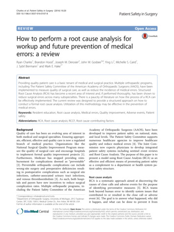
Case Study: Root Cause on Seal Failure in RefineryBySourav Kumar ChatterjeeSr. Manager Reliability ImprovementHPCL Mumbai RefineryMumbai, IndiaMany different factors contribute towards the failure of a pump. Some factors thatdid not seem to have contributed to earlier failures were not examined orconsidered and may become the cause of failure under other situations. Failuresdo not occur suddenly. Usually there are many symptoms, which signal a failuresituation and are generally termed as potential failure modes. The ignorance ofsuch symptoms almost always leads to failure.Below are two case studies pertaining to mechanical seal systems, a vitalcomponent of pumps operating in running process plant.Case A: Even a standby pump can have a seal failure, and ahazard associated with itWe have come across many instances of seal failure or hazard due to sealfailure of running pumps, especially in light hydrocarbon or high temperaturehydrocarbon services, but the fire hazard due to seal failure of idle pump is a rareevent and unpredictable.Pump type and operating parameters: single-stage centrifugal back pulloutdesign, made by Thomson-Byrton. Flanges: 300# 4” suction, 3” discharge.Impeller has balancing holes.Service: Jute Blending (JPB), 2900 RPM, 310 0C, 89.4 m3/hr flow, 90.8 m head,0.67 specific gravity. Suction pressure 1.5 Kg/cm2 (gage units), V.P. @ P.T.(vapour pressure at pumping temperature) is 1.0 Kg/cm2 . Minimum flow (MCSF)is specified by manufacturer as 22.7 m3/hrMechanical parameters: bearings 6311C3/7310; bellows seal with flush plan 02and 62; cooling plan G. Material of major parts: 410ss, 316ss, CS. Lubricationtype: oil lubrication with Turbinol-68This pump did not have on-line monitoring, and thus no alarm or trip signalsavailable.
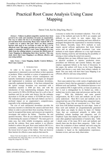
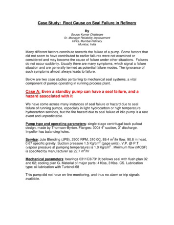
Mating Ring Seal RingBellows Sleeve Purge bush
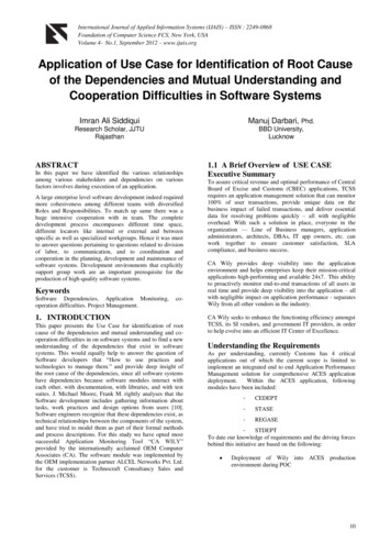
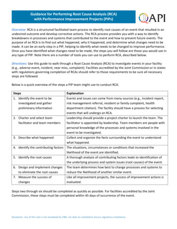
Description of the initial problemTwo pumps are connected to the distillation tower. They are referred to as RCO(Reduced Crude Oil) pump and a JBO (the one described here) pump. Due toprocess yield requirements, the JBO pump operates at 17 m3/hr, which is belowthe minimum flow requirement of 22 m3/hr. In case the tank level drops below acertain value, the JBO draw-off control valve begins to close to raise the fluidlevel which is critical to RCO pump. Unfortunately, this causes problem for theJBO pump, which goes to cavitation leading to subsequent component failuresunder cavitation.AtmosphericDistillation TowerJBO Draw offLevel SwitchJBO PumpRCO Pump
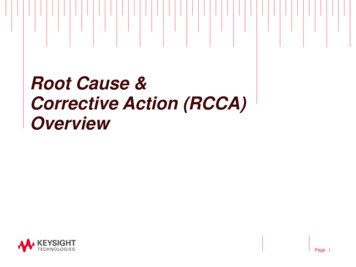
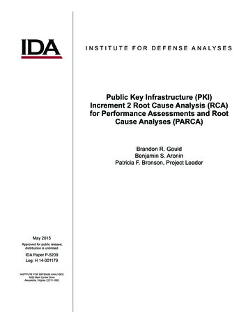
The JBO pump is fitted with single stationery bellow seal having facecombination carbon vs. silicon carbide and initially the flushing plan was 02/62.The seal used to fail (“smoked”) very often indicating inadequate seal facecooling and twice seal failed under situation of starvation. This became highlyalarming as the seal failure caused fire due to flashing of hot product in toatmosphere.To curb the recurrence of such incident two immediate measures were taken:Installed recirculation lineProvided external flushing Plan 32 with TPA media fluid (V.P 1.3 kg/cm2(gage) at 200 0C) at actual pressure of 4.5 kg/cm2 at 150 0C was provided.Seal box pressure was 3.2 kg/cm2V.P kg/cm2gVapour pressure TPA201510500100200300400Temparature Deg CAt first, this modification of system appeared to have solved the problem, butagain there was a seal blow-off event after three months.Surprisingly, this time it occurred to hot standby pump. Hot stand by meansprimed idle pump with discharge valve partially open condition and the fluidrecycling through warm up line by thermal convection, to keep the pump readyfor start in case failure of running one.On investigation it was noticed that external flush to seal box of stand by pumpwas stopped earlier to facilitate adequate flush to running pump seal following apressure drop in external flush media system. The seal blown off while theoperator re-opened the seal flush line after two days to put the subject pumpback in service as per routine changeover schedule.AnalysisDuring suspension of external flush TPA flow, the line content got cooled off dueto stagnation within the bare pipeline. The seal box pressure of hot stand bypump was nearly equal to suction pressure, i.e. 1.5 kg/cm2 (gage). Subsequently
while recommissioning the external flush flow again to the seal box containingservice liquid at above 300 0C , the cold TPA has a fast temperature rise, with aproblem at a pressure much lower than its corresponding vapour pressure (V.Pof TPA at 300 0C is 7 kg/cm2 gage).This had resulted rapid vaporization at seal box and on seal faces as wellcausing opening of seal faces due to sudden pressure rise and the hot JBOflashed in to atmosphere causing minor fire.Action TakenIt was decided and advised to operation crews that the external flush flow mustbe kept ON even the pump is standby. In case an emergency requires to stop theexternal flush flow, the pump must be isolated from the system closing itssuction, discharge, warm-up lines etc.The external flush media source changed to a dedicated system having separatepumps and source for flush. While recommissioning, the external flush to beestablished before opening the suction valve for priming.Case 2: Seal Failure of RCO PumpService – Reduced Crude OilUnit - Fuels Refinery ExpansionMake- M/S Arai JAPANYear of Commission - 1999Type - Two stage. Reverse suction, centerline-mounted between-bearingcentrifugal pump.Process Parameters:Flow: 127 m3/hrSp.Gr: 0.7Process Temperature: 352 Deg CV.P at P.T: 1.5 kg/cm2 gageMinimum Flow: 4 m3/hrSuction Pressure: 1.8 kg/cm2 gageDischarge Pressure: 29.5kg/cm2 gageNPSHa: 2 metersNPSHr: 1.8 metersMechanical Parameters:Radial Bearing- 6311C3 (DE)Thrust Bearing - 6309C3 (double row) (NDE)Shaft sealing – Mechanical seal rotary bellows, Carbon/SC, cartridge typeFlushing Plan –32 (external seal oil)Cooling Plan –G
Stuffing box Pressure: drive end 1.8 kg/cm2 gage, opposite end 13.0 kg/cm2gageMaterials of construction (MOC) of major parts: shaft SS410, impeller CF8M,wear parts-SS316, casing and bearing housing- cast steel.Previous failure history (before introduction of plan-32):The dedicated external seal oil system for the RCO pumpswas commissioned in January, 2003. Initially this pumpwas having flushing plan 22/62 (flushing from pumpdischarge through strainer, cooler and orifice to seal) withsteam quenching.MTBF of seal prior to introduction of Plan 3 was 8 months.The initial flush plan 22 was not effective due to plugging up of cooler andassociated piping, especially while pump used to be standby leading to nonavailability of pump as hot standby. Subsequent to this plan 02/62 was also triedbut it did not improve the situation significantly: seal continued to “smoke” andcovered with coke formation. Ultimately it was decided to provide external flush(virgin gas oil) through a dedicated seal oil system to avoid smoking of seal andadequate seal face cooling, to prevent coke formation and seal leakage.IncidentThe external flush was introduced through orifice of size calculated based on thedifferential pressure between the flush media pressure (16 kg/cm2 gage) andindividual seal box pressure with due consideration to required flow (5 to 6lit/min).Few days after commissioning the system the seal leak reported again, althoughnot as a fire hazard due to presence of the external flush as barrier fluid. It wasobserved the bellows got punctured and uneven wear track on seal faces. Therunout of shaft portion exposed for seal and the gland plate pilot surface truenesswere checked with no noticeable deviations observed. Following this sealassembled with new bellows and the pump was put back to service.The seal leakage started within few hours of operation of the pump.Observations after dismantling the seal:1 - Bellows found ruptured.2 -The seal mating face wear pattern was not concentric.3 - Both the faces were good.4 - Thrust bearing was good and intact.5 - Secondary packing was good and intact.Suspected causes:
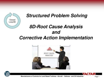
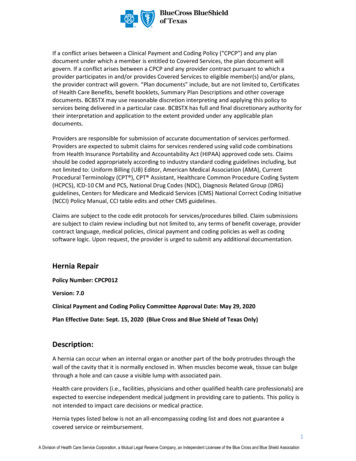
Shaft deflection due to piping stress, unbalance rotor, hydraulic unbalanceOut-of-perpendicularity of shaft with respect to stuffing box faceLow pressure limit of bellows.Analysis:As all process parameters and rotor dynamics symptoms were normal and boththe bearings were good and intact, the possibilities of shaft deflection due tohydraulics / rotor dynamics were ruled out.As a standard procedure, stuffing box, casing & bearing housing bore and facesare machined & maintained concentric and perpendicular with respect to shaft bythe pump manufacture and after machining; all these parts are assembled withproper trueness with help of piloting steps or dowel pin each to avoid the problemof eccentricity and out of perpendicularity. During subsequentdismantling/assembly by user at time of repair/overhauling the factory setdowels/piloting steps act as reference guides to ensure concentric/perpendicularassembly of stationery parts with respect to rotor assembly.The maintenance practice does not specify the checking ofconcentricity/perpendicularity, as a regular activity which is only done in case anysymptom of eccentricity is noticed. It is to be noted that same seal neverdisplayed this type of failure mode prior to introduction of high pressure externalseal flush.Parameters changed after introduction of plan 32 were:1. Stuffing box pressure at NDE increased form 14 bar to 17 bar.As per the seal vendor spec, the max pressure limit for bellows is 15 bar, whichis the border line case and could likely be the cause of bellow failure.Seal: 2.750” Single PBR Cartridge Seal Make: FlowServe Sanmar
Applicablepressurerange2. The pressure limit of PBR seal (4mils bellows AM350 ply thickness) as per thePV graph is 15 bar. The bellows did not develop this type of failure when theflushing Plans were 02/62 and the stuffing box pressures were around 14 bar.When the API Plan was changed to 32, the stuffing box pressures increased to17-18 bar. As the Plan 32 pressure is more than the seal pressure allowablelimit, it could cause over pressurization of the seal and eventually the seal willfail.Immediate actions: Recommended to change the bellows assembly materialto Inconel with a bellows thickness of 8 mils to withstand higher pressure. Thebellows mounting changed to stationery type from rotary type. Thus the rotordynamics (due to torsion) loads and fatigue loads even in presence of anyconcentricity problem, will not affect the bellow stability.
On investigation it was noticed that external flush to seal box of stand by pump was stopped earlier to facilitate adequate flush to running pump seal following a pressure drop in external flush media system. The seal blown off while the operator re-opened the seal flush line after two days to put the subject pump back in service as per routine changeover schedule. Analysis During suspension .