Transcription
CENTRIFUGAL PUMP AND SEAL(API Std. 610 and 682)Presented ByPrakash KumarME(NSPL)
CONTENTS OF PRESENTATION BRIEF ABOUT CENTRIFUGAL PUMPS AS PER Std .API610 . MECHANICAL SEAL DESIGN AS PER Std .API 682 . CASE STUDY ON MECHANICAL SEAL DURINGCOMMISSIONING OF NSPL PUMP AFTER MOH.
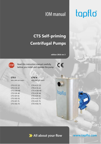
MECHANICAL SHAFT SEAL A mechanical shaft seal consists of two main components: a rotatingpart and a stationary part. The rotating part is axially pressed againstthe stationary part. The mechanical shaft sealisessentially a throttle arranged aroundthe shaft. It reduces leakage between thepump and the surroundings to anabsolute minimum. The clearance between the stationaryand rotating part of the seal must besmall in order to reduce leakage
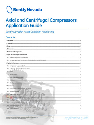
PUMP SHAFTIMPELLERBEARINGS
A LIQUID IS SUPPLIED TO THE PUMP“SUCTION”CENTRIFUGAL FORCE EXPELS THE LIQUID OUTFROM THE IMPELLERAS THE PUMP SHAFT ROTATES
WHY MECHANICAL SEAL ?ROPE PACKING
WHY LEAKAGE ?
STILL LEAKAGE ?
LEAKAGE RATE IS HIGH !!!!
INTRODUCTION OF MECHANICAL SEAL leakage could be controlled to a much greater degree.
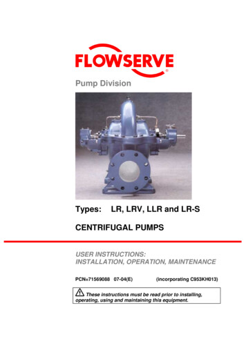
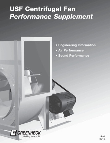
SEALING THE LIQUID It is a fact, all mechanical seals leak. But , leakage is so minute that actualdroplets of liquid are not detected. Instead,the lubricating liquid will vaporize as itcrosses the seal faces and the leakage is agas or vapor. Sealing points of a typical mechanical seal.
The seal gland to thestuffing boxO.D. of the stationarySealing on the shaftAnd finally, the seal faces
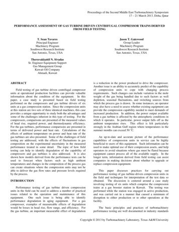
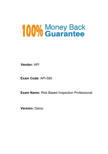
PRESSURE DROP & VAPORIZATION100 psiRotaryFaceStationaryFace0 psi
PRESSURE DROP & VAPORIZATIONLiquid100 psiLiquid VaporVapor LiquidVapor50 psi25 psi0 psi
NSPL PUMP SEAL DESIGN( API 682) Based on API 682, all mechanical seal shall be cartridgedesign.completely self-contained unit (including seal faces,flexible elements, seal gland plate, sleeve, and mating ring) whichis pre-assembled and preset before installation It covers seals for shaft diameters from 20 mm to 110 mm Seal categories : Category 1 seals Category 2 seals Category 3 seals Shaft-to-sleeve diametrical clearance shall be 0.020 mm to0.093 mm (ISO 286-2) .
COMPARISIONFEATURESeal chambersizeCATEGORY 1CATEGORY 2ASME B73.1 and B73.2 API-610, ISO 13709(Chemical dutypumps)CATEGORY 3API-610, ISO 13709Temperaturerange-40ºC to 260ºC-40ºC to 400ºC-40ºC to 400ºCPressure range,absolute20 bar40 bar40 barFace materialCarbon v/s selfsintered SiCCarbon v/s reactionbonded SiCCarbon v/s reactionbonded SiCThrottle bushingrequirements forsingle SealsFixed carbon bushingrequired.Floating carbonbushing optional.Floating carbonbushing orous
CARTRIDGE TYPE MECHANICAL SEALThe same four sealingpoints exist here.Seal Gland GasketStationary O-ringShaft/Sleeve O-ringOne additional sealingpoint exists in thisparticular cartridgeAssembly .Seal Faces
API PIPING PLAN Since the rotating seal will create heat from friction, this heatwill need to be removed from the seal chamber or else the sealwill overheat and fail. A seal piping plan is designed to improve the environmentaround the mechanical seal and therefore increase theperformance and reliability of the seal. Plan 11 is the default seal flush plan for all single seals. In Plan 11, product is routed from the pump discharge to theseal chamber to provide cooling for the seal and to vent air orvapors from the seal chamber. Fluid then flows from the sealcavity back into the process stream It is the most commonlyused flush plan for clean general service equipment. Calculations are required to determine the proper orifice andthroat bushing dimensions to assure adequate seal flush flow.
API PLAN 11WhatSeal flush from pump discharge throughorifice.Default single seal flush plan.WhySeal chamber heat removal.Seal chamber venting on horizontalpumps.Increase seal chamber pressure andfluid vapor margin.WhereFlush should be directed over sealfaces with piping at 12 O’clockposition.
SHARING OF EXPERIENCECASE STUDYHEATING OF MECHANICAL SEAL DURINGCOMMISSIONING OF NSPL MAIN LINE PUMP
POSITION OF MECHANICAL SEALSTUFFING BOXDE SEALJOURNAL BEARINGBEARING GUARDBEARING HOUSINGPUMP SHAFT
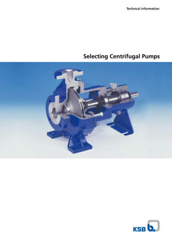
DISMANTLING OF NSPL PUMP SEALFLUSH IN PORTSEAL FACESHRINK DISCSHAFT SLEEVEO- RINGSLEEVE LOCKNUTTHROTTLERINGSEAL HOUSINGLEAKAGE DRAINPORTBEARING HOUSINGSIDESTUFFING BOX SIDE
SEAL PARTSSHAFTSLEEVESEALHOUSINGTHROTTLERINGLOCK NUTSHRINK DISC
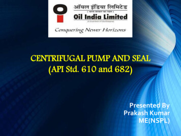
CASE STUDY OVERVIEWBALANCINGLINEDESIDEPLAN 11FLUSHLINENDE SIDE
PROBABLE REASONS ?1st trial run of pumpon 30.12.2013THROTTLE RINGTemp rise of DE side seal (6870 0C)Dismantling of seal doneThrottle ring in wear conditionClearance checked with sleeve,found within limit (0.21 mm)Note : As per API 682, maximum diametrical clearance of floating throttlering is 0.28 mm for shaft ID 81 to 120 mm .
REASONS ? Technical guidance from OEM (Eagleburgmann) of sealDESIDESEAL FLUSHINGLINENDE SIDE
MECHANICAL SEAL HEATINGPress 5 Kg/Cm2Stagnant of process fluid
SEAL QUENCHING Quenching is the introduction of a medium, usuallywater, nitrogen, or steam, on the atmospheric side of amechanical seal assembly. The gland plate is equipped with a throttle bushing toprevent moisture or steam leakage from a quenched sealfrom entering the bearing housing and contaminating thelubricating oil, and to maximize containment of thequench fluid. The quench may be required to prevent solids fromaccumulating on the atmospheric side of the seal.Typically used with a close-clearance throttle bushing.
API PLAN 62Prevent solids buildup onatmospheric side of seal.Prevent icing.
around the mechanical seal and therefore increase the performance and reliability of the seal. Plan 11 is the default seal flush plan for all single seals. In Plan 11, product is routed from the pump discharge to the seal chamber to provide cooling for the seal and to vent air or vapors from the seal chamber. Fluid then flows from the sealFile Size: 1MBPage Count: 32

![API Ballot: [Ballot ID] – API 510 & API 570, Deferrals, Rev05](/img/5/api510andapi570deferralsrev5.jpg)