Transcription
InstallationInstructionsSeal Support ReservoirFlowserve seal support system for dualunpressurized and dual pressurized operationExperience In Motion
IntroductionThis manual covers the installation and operation of Flowserve Seal SupportSystems for dual unpressurized (API Plan 52/ANSI Plan 7352) and dualpressurized seals (API Plan 53A, 53B, 53C/ANSI Plan 7353). The followinginstructions describe the appropriate system, buffer/barrier fluids, installation,start-up and maintenance.ReservoirThe standard supply tank is designed in accordance with ASME Code Section VIII,Division 1. All tanks are welded in accordance with ASME Code Section IX. Tanksinclude inlet, outlet, vent and fill, along with mounting lugs as minimum connection.Sealing System DescriptionSupply tank assemblies can be used as reservoirs for dual seal designs. Thesealing system produced is defined as being either a thermal convection systemor a forced circulation system.Support System DescriptionsAPI Plan 53A, 53B, 53C/ANSI Plan 7353A for dual pressurized sealsAn API Plan 53A/ANSI 7353A is a pressurized dual seal system which is usedin services where no process leakage to atmosphere is tolerated. The systemconsists of dual mechanical seals with a barrier fluid between them. The barrierfluid in the supply tank is pressurized to a higher pressure than the seal chamber,normally 15 to 25 psig (1 to 1.7 bar). Primary (inboard) seal leakage will be barrierfluid into the product. A small amount of leakage is customary.An API Plan 53A/ANSI Plan 7353A is usually chosen over an API Plan 52/ ANSIPlan 7352 for dirty, abrasive or polymerizing products which would either damagethe seal faces or cause problems with the barrier fluid system if an API Plan 52/ANSI Plan 7352 is used. There are two disadvantages to an API Plan 53A/ANSIPlan 7353A which must be considered. First, there will always be some leakageof barrier fluid into the product. Normally, this leakage will be minute, and theleakage rate can be monitored via the level gauges or other instrumentation.However, the product must be able to accommodate a small amount of contamination from the barrier fluid. Secondly, an API Plan 53A/ANSI Plan 7353A systemis dependent on having the supply tank pressure maintained at the proper level.If the supply tank pressure drops, seal leakage direction will be reversed and thebarrier fluid will be contaminated with the process fluid.An Induced Circulation System is essentially the same as the thermal convection system, except for the addition of a circulating device in the seal cavity whichprovides for positive flow in the system. The addition of the circulating deviceprovides for positive flow of barrier/buffer fluid shown in Figure 1. Because supplytanks provide for poor radiation and convection of heat to the atmosphere, it iscommon to add cooling coils inside the reservoir as a means of removing heat.2 Copyright 2008 Flowserve Corporation
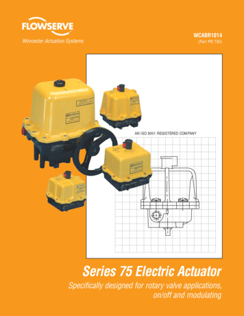
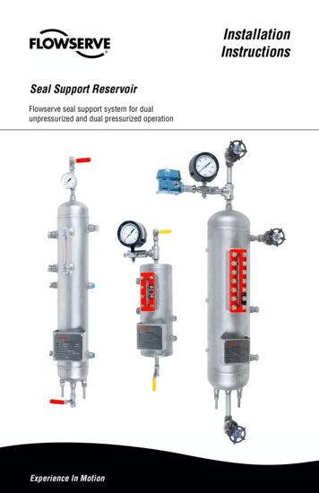
Dual Inside Seal with Induced CirculationThrough Supply Tank with Cooling CoilFigure 1Plan 53A/ANSI Plan 7353AWhatPressurized barrier fluid circulationthrough reservoir.Fluid is circulated by a pumping ringin the dual seal assemblyWhyIsolate process fluidZero process emissionsTypically used 150 psig (10.3 bar) pressurePressure sourcenormally openPressureswitch(low)Bypass linefrom pumpdischargeOrificeoptionPressureindicatorLevel switch (low)4 feet (1.2 m)maximumSupplytankassemblyCoolingcoils1.5 - 2 feet(0.45 -0.6 m)minimumDrainnormallyclosedPlan 53B/ANSI Plan 7353BPlan 53C/ANSI Plan 7353CWhatPressurized barrier fluid circulationwith bladder accumulator.WhatPressurized barrier fluid circulation withpiston accumulator.WhyIsolate process fluid.WhyIsolate process fluid.Higher pressure than Plan 53A.Higher pressure than Plan 53A.Fluid is circulated by a pumping ring inthe dual seal assembly.Zero process emissions.Fluid is circulated by a pumping ring inthe dual seal assembly.Zero process emissions.Dynamic tracking of system pressure.3
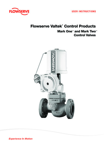
API Plan 52/ANSI Plan 7252 for dual unpressurized sealsAn API Plan 52/ANSI Plan 7352 is an unpressurized dual seal system whichis used in services where no leakage to atmosphere is tolerated. The systemconsists of dual mechanical seals with a buffer fluid between the seals. Thebuffer fluid is contained in the seal pot which is vented to a flare, thus maintainingthe buffer fluid pressure close to atmosphere. Primary (inboard) seal leakage willbe product leakage into the buffer fluid. There will always be some leakage.An API Plan 52/ANSI Plan 7352, Figure 2, works best with clean, non-polymerizing products which have a vapor pressure higher than the buffer fluid pressure.These products will flash in the supply tank and the vapor can escape to the ventsystem. If the product has a vapor pressure lower than the buffer fluid or supplytank pressure, the leakage will remain a liquid and will cause the barrier fluid levelto rise.Should excessive primary (inboard) seal leakage not be detected early, theheavier process fluid will displace the buffer fluid and can result in increasedseal wear.Dual Unpressurized Seal with Induced CirculationThrough Supply Tank with Cooling CoilsFigure 2API Plan 52/ANSI Plan 7352To flareor vaporrecoveryBypass linefrom l switch (high)Level switch (low)4 feet (1.2 m)maximumSupplytankassemblyCoolingcoils1.5 - 2 feet(0.45 -0.6 m)minimum4PressureindicatorDrainnormallyclosed
Buffer/Barrier Fluid SelectionThe following should be considered when selecting a barrier/buffer fluid: Compatibility of the fluid with the process pumpage being sealed so as not toreact with or to form gels or sludge when the fluids are intermixed. Compatibility of the fluid with the metallurgy, elastomers and othermaterials of the seal/flush system construction.For an API Plan 53A/ANSI Plan 7353A pressurized barrier fluid system wherethe method of pressurization is a gas blanket, special attention must be given tothe application conditions and barrier fluid selection. Gas solubility in the barrierfluid increases with the rising temperature and pressure. As pressure is relievedor temperatures cool, the gas is released from the solution and may result infoaming and loss of circulation of the barrier fluid. This problem is normally seenwhere higher viscosity barrier fluids, such as lube oils, are used at pressuresabove 150 psig (10.3 bar). Synthetic barrier fluids offer greater compatibility andwider operating ranges where traditional fluids have problems.The viscosity of the barrier/buffer fluid should be checked over the entireoperating temperature range with special attention being given to start-upconditions. The viscosity should be less than 500 cst at the minimumoperating temperature.1.For services above 50 F (10 C), hydrocarbon barrier/buffer fluids having aviscosity below 100 cst at 100 F (37.8 C) and between 1 and 10 cst at212 F have demonstrated proper operating climate.2.For services below 50 F (10 C), hydrocarbon barrier/buffer fluids having aviscosity between 5 and 40 cst at 100 F (37.8 C) and between 1 and 10 csthave demonstrated proper operating characteristics.3.For aqueous streams, mixtures of water and ethylene glycol or propyleneglycol are usually adequate. Commercially available automotive antifreezeshould never be used. The additives in antifreeze tend to plate out (leave aresidue) on seal parts and cause failure as a result of gel formation.Note: Ethylene glycol may be considered a hazardous material and/orhazardous waste when used as a barrier fluid.4.The fluid should not freeze at the minimum site ambient temperature.5
Fluid volatility and toxicity of the fluid must be such that the leakage to theatmosphere or disposal does not impose an environmental problem.1.The fluid should have an initial boiling point at least 50 F above thetemperature to which it will be exposed.2.The fluid should not have a flash point higher than the service temperatureif oxygen is present.The fluid should be able to meet the minimum 3-year continuous seal operationcriteria without adverse deterioration. It should not form sludge, polymerize orcoke after extended use.1.For hydrocarbon streams, paraffinic-based high purity oils having little or noadditives for wear/oxidation resistance or synthetic based oils have beenused successfully.2. Anti-wear/oxidation-resistant additives in commercial turbine oils have beenknown to plate out on seal faces.Installation61.The reservoir is mounted vertically not more than 3 feet (0.9 meters) fromthe seal gland to the vertical centerline of the reservoir. The bottom of thereservoir is mounted 18 to 24 inches (45.7 to 61 centimeters) above thehorizontal centerline of the pump.2.It is highly recommended that the reservoir be flushed with clean fluid priorto equipment start-up to remove any foreign matter from the system.3.All lines from the seal cavity to the reservoir must slope upward at all points.The upward slope should be a minimum of 1/4 inch per foot with all bendsbeing large radius. The minimum size for tubing should be 3/4 inchdiameter. Tubing is recommended.4.Connect the supply connection (lower seal connection on the reservoir)to the bottom (inlet) gland connection (BI - inlet).5.Connect the return connection (upper seal connection on the reservoir)to the upper (outlet) gland connection (BO - outlet).6.If the reservoir is equipped with cooling coils, connect water lines to the coilconnections on the bottom of the reservoir.7.Remove all plastic shipping plugs and properly seal or attach pipingwith metal connections.8.Connect wiring to any instruments included with the system such as apressure switch/transmitter or level switch/transmitter.
9.If the system is equipped with a weld pad level gauge the bolts on the covershould be retorqued to 20 ft/lbs. (Tighten in 5 ft/lb increments starting withthe center bolts and working out.)10. Connect vent connection to flare or vapor recovery system (Plan 52).Do not open vent valve until reservoir has been filled with buffer fluid.11. Fill reservoir with barrier/buffer fluid to the middle of the sight glass.Gas volume of the system should be at least 25 percent of the reservoirvolume to allow for thermal expansion during operation.12. Before starting the system, bleed all air from highest point in the system.13. Connect external pressurization to reservoir on Plan 53A, B, C (dual seal).A pressure regulator and check valve are required to maintain a constantpressure on the system. The pressure in the reservoir should be maintainedat least 25 psi (1.7 bar) above the seal cavity pressure.Make sure reservoir is filled before pressurizing.Start-Up1.API Plan 52/ANSI Plan 7352 - open the valve to the vent or flare system slowly.2.API Plan 53A, B, C/ ANSI 7353 - slowly open the valve between reservoirand external pressurization source. Slowly increase the pressure to avoidgas ingestion. Check for leaks as unit is being pressurized. Operatingpressure is normally 15 to 25 psig (1 to 1.7 bar) above seal cavity pressuredepending on seal design. The pressure gauge on system can be used tomonitor system pressure.3.If system is equipped with cooling coils, open the valve to allow water to flowthrough coils.4.The pump can now be commissioned for start-up per the equipmentmanufacturer's recommendations and all plant safety and start-upprocedures.MaintenanceDuring planned plant shutdowns, it is recommended maintenance practice that thebuffer/barrier fluid be drained, reservoir flushed and new fluid put in the reservoir.This will ensure the quality of the buffer/barrier fluid used to lubricate the seals andhelp remove any particles that may have accumulated in the reservoir.When changing or cleaning the glass on armored sight gauges (weld pad levelgauge), always install new gaskets and retorque bolts to proper amount. It is alsorecommended that the bolts be checked and retorqued prior to first operation.They can come loose during shipping and transport.7
TO REORDER REFER TOB/M #F.O.FIS123eng REV 11/08 Printed in USATo find your local Flowserve representativeand find out more about Flowserve Corporation,visit www.flowserve.comUSA and CanadaTulsa, Oklahoma, USATelephone: 1 918 599 6062Telefax: 1 918 583 1071Flowserve Corporation has established industry leadership in the design and manufacture of its products. Whenproperly selected, this Flowserve product is designed to perform its intended function safely during its useful life.However, the purchaser or user of Flowserve products should be aware that Flowserve products might be usedin numerous applications under a wide variety of industrial service conditions. Although Flowserve can providegeneral guidelines, it cannot provide specific data and warnings for all possible applications. The purchaser/usermust therefore assume the ultimate responsibility for the proper sizing and selection, installation, operation, andmaintenance of Flowserve products. The purchaser/user should read and understand the Installation Instructionsincluded with the product, and train its employees and contractors in the safe use of Flowserve products in connectionwith the specific application.While the information and specifications contained in this literature are believed to be accurate, they are supplied forinformative purposes only and should not be considered certified or as a guarantee of satisfactory results by reliancethereon. Nothing contained herein is to be construed as a warranty or guarantee, express or implied, regarding anymatter with respect to this product. Because Flowserve is continually improving and upgrading its product design,the specifications, dimensions and information contained herein are subject to change without notice. Should anyquestion arise concerning these provisions, the purchaser/user should contact Flowserve Corporation at any one ofits worldwide operations or offices. Copyright 2008 Flowserve CorporationEurope, Middle East, AfricaEssen, G
API Plan 53A, 53B, 53C/ANSI Plan 7353A for dual pressurized seals An API Plan 53A/ANSI 7353A is a pressurized dual seal system which is used in services where no process leakage to atmosphere is tolerated. The system consists of dual mechanical seals with a barrier fluid between them. The barrier