Transcription
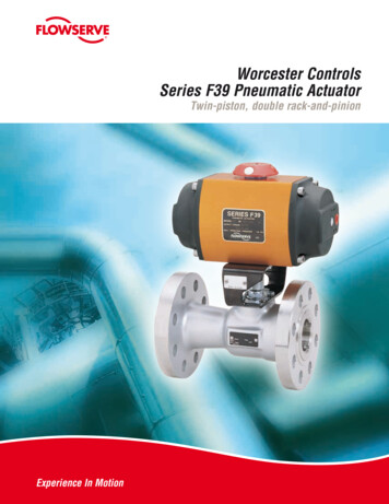
WCABR1014Worcester Actuation Systems(Part PB 730)AN ISO 9001 REGISTERED COMPANYSeries 75 Electric ActuatorSpecifically designed for rotary valve applications,on/off and modulating
Flow Control DivisionWorcester Actuation SystemsWorcester Controls Series 75A time-tested, high-quality state-of-the-art electric actuator for remote control of quarter-turn valves andother rotary devices. Simple, compact and reliable.Series 75 Electric Actuators from Worcester Actuation Systems add anew dimension of operational dependability and flexibility to modernprocesses controlled by computers, programmable controllers andother electric control equipment. A multi-function capability permits useof the Series 75 actuator throughout the process for on/off, throttling,variable-cycle and any analog or digital control. One of the most reliableelectric actuators on the market, the Series 75 is lightweight, compactand powerful. Its split phase capacitor AC reversing motor or DC motordrives a valve through a sealed, permanently lubricated gear train whichoffers virtually lifetime maintenance-free dependable operation.The Series 75 is available in eight sizes and produces torques to 3000in-lbs. Housings are designed to TYPE 1 General Purpose, TYPE 42Watertight, and TYPE 7, Class 1, Division 1 and 2, Group C, D andTYPE 9, Class II, Division 1 and 2, Group E, F, G. A combined locationTYPE 4, 4X, 7, 9 enclosure is also available as a “Z” option. A bakedpolyester finish is the standard coating, but special coatings are available for extreme hazardous-environment applications.Series 75 actuators may be used on Worcester Controls complete lineof ball valves, other quarter-turn valves or devices requiring rotaryoperators. Moreover, their ability to provide power in both directionsthrough selected arcs from 20 through 300 makes them ideal forcontrol of heating, ventilating and air conditioning duct systems andautomatic, remotely operated equipment.WCABR1014
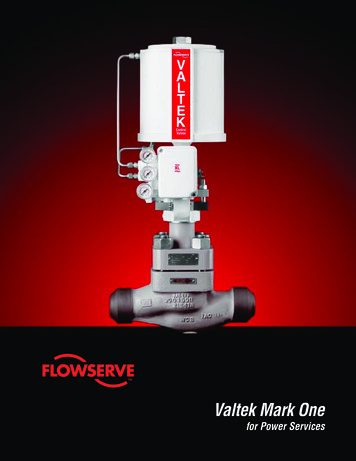
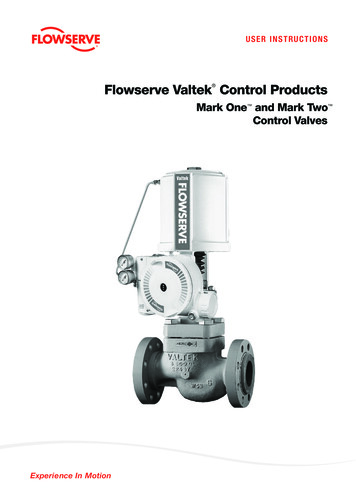
Flow Control DivisionWorcester Actuation SystemsOptions to Fit Your ApplicationsThe Series 75 can be ordered with a variety of options to tailor it tothe needs of your application.Cycle Length Control – This speed control feature allows field adjustment of opening and closing cycle times, 19 minutes for 25% dutyand 57 minutes for 75% duty actuators.Feedback (0-1000 ohm) Potentiometer – provides a variable resistance to signal the exact position of the output shaft and the valve itis powering.TYPE 4Sizes 10, 12, 15, 20, 22(Enclosure Option – W)Position Indicator Board – provides a 4-20 mA valve position feedbacksignal to the control room.Heater/Thermostat – prevents condensation from collecting inside theactuator.Condensation Drain Plug – drains accumulated water.180 Center-Off Kit – provides an extra position for three-way valvesand is used for dribble-feed applications in quarter-turn valves.TYPE 1Sizes 10, 12, 15, 20, 22(Enclosure Option – Blank)Additional Limit Switches – may be used to operate lights that indicate valve position or to operate other equipment.AF-17 Positioner Board – for control valves positions the actuatorbased on an input signal of current, voltage or resistance.DFP17 DataFlo P – is a microprocessor-controlled electronic positioner with software for on-site or remote operation and diagnostics.This new, smart positioner for Series 75 actuator driven controlvalves is controlled by a 4-20 mA analog signal from a PLC or digitally from a computer.DFC17 DataFlo C – is a microprocessor based PID single-loop controller that accepts a variety of process inputs. All process parametersare easily programmed through the keypad or via a simple RS-485computer interface.I 75 Low-Current Circuit Interface – is a solid-state interface/relaybetween the PC/controller/computer and actuator motor(s). It protects controlling device outputs from destructive feedback. Thishigh-voltage feedback is due to limit switch action, auto transformereffect of unused winding, and capacitor voltage. The unit, as a printedcircuit board, is conveniently mounted inside of standard enclosures.Maximum output ratings are 4 A for 120 VAC and 2 A for 240 VAC.Controllers with outputs that have low current ratings cannot be connected to electric actuator motor(s) that require a current greater thanthe controller rating.R 75 Remote Terminal Unit (RTU) – is an interface for DC poweredactuators. This solid-state interface card allows you to control a DCpowered electric actuator by a control signal from the RemoteTerminal or any low current system (such as a solar powered system). It is equipped with a field-adjustable current limiting circuit,which will trip the power in case of abnormal conditions (it will resetby reengaging the control signal). Optional contact closure to indicatethe tripped condition; 0-5 VDC, 0-1000 ohm position feedback, andend of travel SPDT gold contact switches are available.WCABR1014Combined TYPE 4, 4X, 7 & 9Sizes 10, 12, 15, 20, 22, 23(Enclosure Option – Z)TYPE 7 & 9Sizes 10, 12, 15, 20, 22(Enclosure Option – X)DFP17 Positioner for ControlValvesCombined TYPE 4, 7 & 9Sizes 25, 30(Enclosure – Z)3
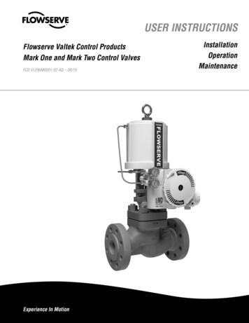
Flow Control DivisionWorcester Actuation SystemsSpecificationsSizes:Small: 10, 12, 15, 20, 22, 23Large: 25, 30Torque:150-3000 in-lbs.Enclosures:TYPE 1 General PurposeTYPE 4 WatertightTYPE 7, Class I, Division 1, 2,Group C, DTYPE 9, Class II, Division 1, 2,Group E, F, G HazardousLocationsTYPE 4, 4X, 7, & 9 CombinedLocationsEnclosure Coatings: Corrosionresistant baked polyester finishstandard. Consult Flowserve forspecial applications.Voltages:120 V and 240 VAC, 12 V and24 VDCConnection:Male output shaft (female shaftavailable on request)Gearing:Small: Sealed, permanently lubricated spur gear module driving afinal dual-torque bull gearLarge: Two-stage planetary gear,permanently lubricated self-locking gear trainOverload Protection:AC only. Thermal overload protector with automatic reset.Travel Stop Limit Switches:Two SPDT, all sizes; internal,independent, adjustable.Actuated by cams mounted ondrive shaft. Adjustable from 20 to 300 .Manual Override:All sizes, TYPE 4, 7 and 9 only.Lift position indicator and turnshaft: Sizes 10,12,15, 20,22, 23.Turn side-mounted handwheel:Sizes 25 and rquein.-lbs.150120VoltagesCurrent at rated stall torque – ampsDutyCycles90 Timeseconds120 VAC240 VAC12 VDC24 VDC—12, 2412, 2410%25%75%2.5517, 151.5.70.30.60.40.15—1.40.50—.70.25ACDC120, 240120, 240120, 240Approx.WeightLbs. (kg.)8.20(3.70)120—100%17.25————12, 2412, 24—10%25%75%100%4827, —8.20(3.70)1275225180120, 240120, 240120, 75600480120, 240120, 240120, 240120—12, 2412, 24—10%25%75%100%2.5517, 80—9.50(4.31)2275*900720120, 240120, 240120—12, 2412, 2410%25%75%4827, .31)23751200950120, 24012, 2475%25.70.302117.70(8.04)257518001440120, 21.80)120, 240307530002400120, 240120, 240Options:All sizes, all enclosures. CycleLength Control (CLC), dual- orsingle-feedback potentiometer,4-20 mA position indicator,heater/thermostat, condensationdrain plug (V-53), 180 centeroff (three-position), additionallimit switches, mechanicalbrake, I-75 computer interfaceunit, various duty cycles, positioner, set point controller.Temperature Limits (All models):-40 F (with heater and thermostat) to 150 F max. (At elevatedtemperatures, duty cycle mustbe derated. Consult Flowserve.)—Actuator SizingThere are a few terms associated with electric actuators thatrequire definition. Actuator Start-up Torque is the amount oftorque initially produced by an actuator when starting fromrest. Use start-up torque when sizing an electric actuator for aball valve that is used for either on/off or throttling service.Actuator Stall Torque is the amount of torque produced by theactuator just prior to the point where the motor stalls. Do notuse stall torque for sizing.OVERCURRENT PROTECTION WARNING!Where overcurrent protection is used in the actuator powercircuit, it is recommended that the protection rating not beless than the values listed in the table:Actuator SizeVoltageProtection Rating10-23120 VAC5 amps25/30120 VAC10 ampsConduit Connection:One 1/2" NPT - Two 1/2" Optional(Size 23 has 3/4" NPT)10-23240 VAC3 amps25/30240 VAC5 ampsOperation:Reversing (bidirectional) foruse with quarter-turn valvesor rotating equipment to fullrotation.10-2312 VDC10 amps10-2324 VDC5 ampsLubrication:Permanently lubricated geartrain. Self-lubricated bearings.WCABR1014
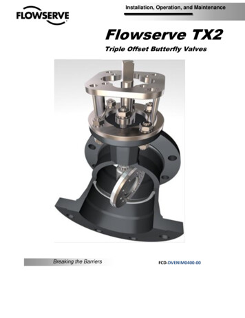
Flow Control DivisionWorcester Actuation SystemsDimensionsinches (mm)6.53(165.9)5.53(140.5)3.00(76.2)Sizes 10, 12, 15, 20, 22TYPE 1 (General Purpose)1/4" - 20 UNC TAP x .38 (9.7) DEEP(4 HOLES).69(17.5)1.06(27.0)6.31(160.31.38 (35.1)1.44 (36.6).53(13.5)A1.00(25.4)2.00(50.8)B#10 - 32 UNF TAP x .31(7.9) DEEP(4 HOLES)1/2" NPT(Main Outlet)C.94(23.9)Cover Removal Allowance: 3.62 inches min.FG1/4" - 20 UNC TAP x .38 (9.7) DEEP(4 HOLES).69 (17.5)HMAX.97 (24.6)1.38 (35.1)1.06 (27.0) SQA1 Main Outlet1 Optional1/2 " NPT(Sizes 10-22W&X enclosures)1" - 28 UNC TAP X .50(12.7) DEEP( 4 HOLES)BCover Removal Allowance: 6.27 inches min. '% ' % % D % %% ' %% % % ! "#! %% %6.34(161.0)4C#10 - 32 UNF TAP x .31 (7.9) DEEP(4 HOLES)Sizes 25, 30TYPE 4 (Watertight) andTYPE 7 & 9 (Hazardous Locations)Combined Enclosure - Z3.17(10.5)1 Main Outlet3/4 "NPT(Sizes 10-23Z-enclosures)1.94 (49.2).53 (13.5) TYP1.00(25.4)2.00(50.8) 2.114.22 (53.6)(107.2)DESizes 10, 12,15, 20, 22, 23TYPE 4 (Watertight) Enclosure - W,TYPE 7 & 9 (Hazardous Locations) Enclosure - X,TYPE 4, 7 & 9 (Combined) Enclosure - Z (shown)1/4" - 28 UNF TAP x.62 (15.7) DEEP(4 HOLES)(2375 ONLY)1.00(25.4) '1.44 TYP(36.6) %' '2.88 TYP(73.2) MOUNTING PATTERN ) * ,- . Type 1, Sizes 10, 12, 15, 20, 22 % %All other types and sizesDIMENSIONS INCHES (mm)Size10, 1215, 16.80)C.59(15).80(20.32)D.36(9.14).50(12.70) ( DIMENSIONSDSizeEnclosureABC10, 1215, (245.90)9.68(245.90)5
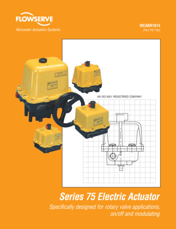
Flow Control DivisionWorcester Actuation SystemsWiring DiagramsDesign OptionsIMPORTANT!Feedback Potentiometer12Mechanical BrakeA feedbackpotentiometer isused when remoteindication is desired.Potentiometers areavailable in1000 ohms.PURPLEWHITE / BLKNOTE: ACTUATOR SHOWN IN COUNTERCLOCKWISE EXTREME OF TRAVEL, OR"OPEN" POSITION.11GREENEACH ACTUATOR SHOULD BE ELECTRICALLY POWERED THROUGH ITS OWNINDIVIDUAL SINGLE-POLE SWITCH CONTACTS TO ISOLATE THE UNUSED WINDING.10FEEDBACKPOTENTOMETERCDA mechanical brake isused for all butterflyvalve applications orwhen the actuatormust be stoppedinstantaneously andsecurely. (Used on10-23 sizes only.)Available for ACactuators only.(AC)MECHANICAL BRAKEHEATER / THERMOSTAT37REDBLACKORANGESizes 10-30 AC PowerNCNCSWITCHES SHOWN INCENTER - OFF POSITIONARMATUREBLUEBLACK1011567CLCPULSE CWOR CLOSEACTUATORTERMINALS1234567CUSTOMER WIRING120 VAC HOTNEUT.12Limit SwitchesCUSTOMER PROVIDED LIGHTSL2AND SWITCHING:87 DCVOLTSBRN/WHITEL19CLC78 9 1011 12ACTUATORTERMINALS12WHITE TOMOTOR94CUSTOMER WIRINGBLACK83RED7PULSE CCWOR OPEN120 VAC HOTWHITE62NEUT.BROWN520 THRU 23SIZES ONLYRED4YEL.3BRN.2BLK.1REDREDCUsed with threeway valves orsimilar productsrequiring a midposition stopcapability forshutoff. May beadjusted for travelother than 180 .ORANGEBLUEBLUEN.C.NOTE: A three-position switch is requiredfor operation.ORANGEN.C.N.O.C SW - 1CLC1BRN/WHITEGRAYORANGES.W. - 2GREYCNOC.C.W. SWITCHNOC.W. SWITCHN.O.Cycle Length Control (CLC)ACTUATORTERMINALS180 Center-off(three positions)4NOTE: A 2" CPT valve should not be sized withan electric actuator smaller than 2275, and amechanical brake must be ordered.BLACKREDWHITEBLACKA heater/thermostatkit for cold ambienttemperatures orhumid environmentsuses a 15-wattheater and a thermostat set to closeat temperaturesbelow 70 F ostat345PULSE CW & CCWOR BOTH OPEN & CLOSE67CUSTOMERWIRINGNEUT.AC HOTSizes 10-23 DC PowerONE EXTRA LIMITSWITCH WITH CAMOne Limit SwitchNOTE: AC and DC wiring diagrams shownare for W, X and Z enclosures only. DCwiring diagram shown is for size 10, 20 and23 actuators. For size 12 and 22 actuators,the red/black motor leads are reversed.TWO EXTRA LIMITSWITCHES WITH CAMSTwo Limit SwitchesMay be mounted to either operate lights,indicate valve position, or operate otherequipment such as pumps, compressors, mixers, etc.10 -30 C 75 120A/240APrevents destructive pipeline shock caused byfast opening or closing valves on steam orhydraulic service. The CLC units allow fieldadjustment of the standard actuator’s cycletime up to approximately 19 minutes for 25%duty and 57 minutes for 75% duty actuators.Additional Options Available. Consult Flowserve.6WCABR1014
Flow Control DivisionWorcester Actuation SystemsSizes 10-23Sizes 25, 30Sizes 10-23Item Qty.DescriptionMaterialItem Qty.DescriptionMaterial1234567811111211Aluminum CastingAluminum CastingZinc CastingZinc CastingSteelSteelSteelPhenolic se PlateMotor ModuleOutput ShaftGear Drive PinBull GearCapacitor (w/FiberWasher if Required)Capacitor BracketTerminal StripLimit SwitchLimit Switch CamCam Set ScrewLimit Switch ScrewBase Plate ScrewHex Screw (W,X,Z)SteelPolyethylene Based MaterialPhenolic EncapsulatedZinc CastingSteelSteelSteelStainless Steel1617181920202122232425262728293031Hex Screw (GP)Position Indicator (W,X,Z)Indicator Set Scr
Large: Two-stage planetary gear, permanently lubricated self-lock-ing gear train Overload Protection: AC only. Thermal overload pro-tector with automatic reset. Travel Stop Limit Switches: Two SPDT, all sizes; internal, independent, adjustable. Actuated by cams mounted on drive shaft. Adjustable from 20 to 300 . Manual Override: All sizes, TYPE 4, 7 and 9 only. Lift position indicator and .