Transcription
Getting Started withVectorworks Architect
Getting Started with Vectorworks ArchitectTable of ContentsIntroduction .2Section 1:Program Installation and Setup .6Installing the Vectorworks Architect Program .6Exercise 1: Launching the Program and Opening the Starting File.7Exercise 2: Adjusting Preference Settings.9Section 2:Laying Out Room Areas .12Exercise 3: Drawing Exterior Walls.13Exercise 4: Drawing Interior Walls.22Exercise 5: Drawing Second Floor Walls, and Adding a Stair .26Section 3:Creating Architectural Elements.34Exercise 6: Creating the First Floor Plan .35Exercise 7: Creating the Second Floor Plan.46Section 4:Working with Multiple Levels .53Exercise 8: Creating and Modifying the Roof .54Exercise 9: Editing Architectural Elements .57Section 5:Creating Construction Documents.61Exercise 10: Generating Construction Drawings .62Exercise 11: Adding Annotations.72Vectorworks 2010 - 1
Getting Started with Vectorworks ArchitectIntroductionWelcome to Vectorworks Architect! This tutorial will introduce you to key tools and techniques for drawing and editing, and a streamlined workflowwhich provides the proper framework for exploring the full power of Vectorworks Architect on your own.Important: For free tutorial updates and instructional videos, visit the Architect Getting Started website.Overview of the Modeling ProcessIn this thematic tutorial, you use Vectorworks Architect to design a modern vacation home. You begin with a pre-configured (but otherwise blank)starting file, and continue using this single file for all design phases and documents. You complete the project by creating various constructiondocuments:Note: The house design in this tutorial was adapted from the award-winning Dwell Home design by Resolution: 4 Architecture.As you work through 11 continuing exercises, you develop the house design using a combination of Vectorworks standard and VectorworksArchitect tools to complete the following design features in order: Room layouts (walls)Architectural elements (floors, doors, windows, and other symbols)Multiple level features (roof)Construction documents (commonly used)AnnotationsNotes:1) Starting with Exercise 3, you can optionally open completed exercise files (available in the Data Set folder) to check your model or to skipahead to the beginning of the next exercise. For example, open the GS-VWAx10.vwx file (completed Exercise 10) to start at the beginning ofExercise 11 (see the General Exercise Tips section for more information).2) This tutorial focuses on creating or setting up only the most common construction documents for a house design project.Vectorworks 2010 - 2
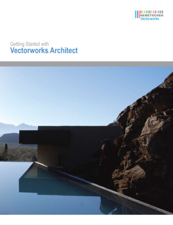
Getting Started with Vectorworks ArchitectHow to Use This TutorialThis tutorial is provided as an e-Book, in PDF format. You can print any or all pages for reference, or you can view the tutorial on-screen forenhanced electronic benefits including navigation links and search features.If you choose to view the tutorial on-screen, you can optionally enable Reflow viewing mode (available from the View menu only in the AdobeReader 7 or Adobe Acrobat 7 programs, available from the View Zoom menu in newer versions) to display the text with a wrapping effectsimilar to a web browser. You can then adjust the Zoom level, and resize both the tutorial and Vectorworks windows to display them side-by-sideas shown.Notes:1) You can review workflow sequencing and locate specific procedures by scanning the process lists at the start of each section. The process listsare also hyperlinked to facilitate navigation.and Next Viewtools at the bottom of the screen (or available in the2) If you view the tutorial on-screen, look for the Previous ViewPage Navigation toolbar in newer versions). These useful tools—available in Adobe Reader and Acrobat—let you revert or repeat navigationalchanges by page controls, bookmarks, and hyperlinks.3) If you use Reflow viewing mode with the Adobe Reader window configured as shown in the figure above, you may need to temporarily increasethe size of the window to see details in larger figures.4) The Adobe Reader Search toolIntroductionprovides more extensive options for searching text than the Find command.Vectorworks 2010 - 3
Getting Started with Vectorworks ArchitectGeneral Exercise TipsUse the following tips to facilitate working with your exercise drawing files: Read each step carefully and make sure your results match the figures. If your results vary from the figures, stop immediately and reviewthe previous steps. If you can’t find the problem quickly, start the exercise over with the appropriate supplied file. Alternate methods are shown for activating many tools, commands, and modes. Use the method that works best for you. In many cases, you must click in the drawing area after using the Navigation palette before continuing with the next step. Watch for SmartCursor cues that appear when you hover your cursor over significant drawing object geometry. Pause briefly over snappoints to display the red snap box, and watch for the red confirmation dot displayed temporarily after you complete the snap. When toomany red snap boxes are displayed in congested areas, press the Esc key once to clear the display. For some operations, additional view adjustments may be required. For these cases, press the Z key for the Snap Loupe shortcut, or usethe Zoom, Pan, and Fit to Objects tools as required. If you have a mouse wheel, use it to zoom in and out. To pan across the drawing at any time (even if a tool or command is active) hold down the Space Bar and drag the cursor. If you inadvertently cleared a selection required for an active tool or command, press Space Bar X temporarily, and then select theobject(s). Many tools have different operational modes, which you can select in the Tool bar (located above the drawing window). Keep the Object Info palette open (to open it, select Window Palettes Object Info). It displays valuable information, and providesaccess to key properties of selected objects. Press the Esc key to cancel any operation. If you are using a tool, it will still be active, but you can then start drawing again or chooseanother tool. Sometimes, you must press the Esc key before you use a keyboard shortcut to activate another tool. Use the Undo command in the Edit menu to revert steps as necessary (both drawing and view changes are reverted). For tools that create multiple segments (such as the Wall tool) press the Delete key once while the tool is active to revert a single segment,or press it repeatedly to revert additional segments. If multiple files are open, you may need to click the Resource Browser’s Home buttonif your house file isn’t active. Object artifacts may remain in the drawing area after some drawing and editing operations. To refresh the screen and clear the artifacts,double-click the Pan tool(in the Basic tools palette). Save your files often to prevent data loss.Important:1) Exercise steps in this tutorial are based on default preference settings from a new installation of the Vectorworks Architect program. Results forsome steps may vary from the figures if your preference settings differ from the defaults.2) Close any open files before you open a completed exercise file (only if you plan on using it to start the next exercise).Using Metric Units with ExercisesAll exercise data set files for this tutorial are set to use imperial units. If you want to use metric values for the exercise steps, enter the valuesexactly as shown in [square brackets, with the unit mark], and Vectorworks will convert the values accordingly. If you want to measure distancesor drawing objects for reference, use the appropriate dimension tool and object snaps to create temporary dimensions, which are set by default todisplay alternate units in metric values. Delete the temporary dimensions when finished.Note: For proper exercise operation—and to validate your results with the imperial figures—do not change the document's units setting to metric.IntroductionVectorworks 2010 - 4
Getting Started with Vectorworks ArchitectChecking Your WorkThe GS-VWAxCheck.vwx file is included in the Data Set folder so you can verify the accuracy of your file. If you want to use this file to check yourwork:1. Copy the Data Set folder to any location on your hard disk.2. In Step 3 of Exercise 1, open the GS-VWAx01.vwx file in the Data Set folder, and then save the file under the name House.vwx in the DataSet folder on your hard disk.Notes:1) Before you use any of the supplied files to start any other exercise, save your current file under a different name, and then open the read-onlyfile (from the Data Set folder on your hard disk) and save it as House.vwx in the Data Set folder.2) You must name your file “House“ and save it in the Data Set folder to ensure the GS-VWAxCheck.vwx file works properly.3. After saving your House.vwx file at the end of exercises 3 through 11, open the GS-VWAxCheck.vwx file from the Data Set folder on yourhard disk, and then follow the exercise-specific checking instructions exactly as shown in the last steps of the exercise.Keyboard ShortcutsAll keyboard shortcuts included in this guide are based on the Windows operating system. If you’re using a Mac, use the Option key instead of theAlt key, and use the Cmd key instead of the Ctrl key. Refer to the Vectorworks 2010 Shortcuts PDF file (available from the Online Help) to print acomplete list of your own keyboard shortcuts.IntroductionVectorworks 2010 - 5
Getting Started with Vectorworks ArchitectSection 1: Program Installation and SetupIn this section, you start by installing the Vectorworks Architect program. Following installation, two exercises cover the following program setupand interface adjustment processes: Activating the Architect workspace (pg 7)Opening the starting file (pg 8)Adjusting Vectorworks preferences (pg 9)Adjusting snapping settings (pg 10)Adjusting Grid and Smart Point settings (pg 10)Setting the default font (pg 11)Adjusting the Navigation palette display (pg 11)In these exercises, you activate (or reset) the Vectorworks Architect interface, and then you adjust program preference settings and adjust theinterface.Installing the Vectorworks Architect ProgramNote: If you have already installed Vectorworks Architect, start with step 2 below.1. Follow the installation instructions in the ReadMe file located in the root folder of your installation DVD.2. Start the program. You can do this by selecting Programs Vectorworks2010 Vectorworks2010 from the Windows Start Menu.3. From the menu, select Help Check for Updates. If updating is necessary, follow the on-screen instructions.4. After updating, close Vectorworks (if it’s still running) to reset the program.Vectorworks 2010 - 6
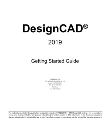
Getting Started with Vectorworks ArchitectExercise 1: Launching the Program and Opening the Starting FileIn this exercise, you launch the application and activate the Vectorworks’ Architect workspace. After a brief orientation of the Architect interface,you then open the supplied starting file.Activating the Architect workspaceYou start by launching the Vectorworks program.1. From the Windows Start Menu, select Programs Vectorworks2010 Vectorworks2010.2. From the menu, select Tools Workspaces Architect. If the Architect workspace is already active, select it again to reset the interface.Position the Navigation palette where shown, and examine key areas of the interface identified in the following figure.View barTool barNavigation paletteAttributes paletteSnapping paletteBasic toolsTool SetsMessage barProgram Installation and SetupObject Info paletteScroll barResource BrowserVectorworks 2010 - 7
Getting Started with Vectorworks ArchitectOpening the starting fileNext, you open the supplied starting file. To save time, this starting file contains many pre-configured resources, and is already fully set up forcreating a two story structure without a basement.Note: Before you open the supplied starting file, see Checking Your Work in the Introduction.3. From the menu, select File Open. In the Open Vectorworks Drawing dialog box, open the Data Set folder and open the read-onlyGS-VWAx01.vwx file. The page boundary is displayed, and it’s ready for laying out the first floor room areas.4. From the menu, select File Save As, and save the file under the name House.vwx.You can now skip ahead to Exercise 2, or you can use the Online Help to review the following commands that were used to set up this file: Document Setup – Specifies layer scale, drawing area (page setup), sheet border, and title block settings used by theCreate Standards Viewports command. Model Setup – Creates basic design layers, with appropriate height settings for 3D objects. Create Standard Viewports – Creates design layer, sheet layer, sheet layer viewport, and class schemes appropriate for selectedconstruction documents. Also creates matching “working” views, which you use throughout the project to facilitate file navigation. Standard Naming – For enabling the Auto-classing option to assign class names and attributes to many of the objects you create.Visibility of these classes is handled automatically in sheet layer viewports and saved views generated by the Create Standard Viewportscommand.Notes:1) Design layers are used in architectural projects as spatial containers for creating drawing objects.2) Sheet layers provide a 2D-only page layout environment for printing.3) Sheet layer viewports are individual 2D “live camera view” objects that reside on sheet layers, but display 2D and 3D drawing objects on designlayers. When you modify drawing objects on a design layer, the viewport itself doesn’t change, but it displays the changes in the design layers.4) Classes are used to control display properties of drawing objects.Important: As you start the tutorial, do not be concerned if you don’t fully understand the file structure and setup commands. As you progressthrough the exercises, you will see how the file structure works in context of a design project.Program Installation and SetupVectorworks 2010 - 8
Getting Started with Vectorworks ArchitectExercise 2: Adjusting Preference SettingsIn this exercise, you verify and adjust program preferences.Adjusting Vectorworks preferencesNext, you verify or adjust key application preference settings to ensure proper exercise operation, turn on scroll bars to facilitate navigation, andincrease the maximum number of undos so you can revert exercise steps if necessary.1. From the menu, select Tools Options Vectorworks Preferences. In the Vectorworks Preferences dialog box, select the Edit tab, and thenverify or adjust settings as shown (keep the dialog box open for the next three steps).2. Select the Display tab, and enable the Scroll bars option, and then verify or adjust other settings as shown.Program Installation and SetupVectorworks 2010 - 9
Getting Started with Vectorworks Architect3. Select the Session tab, and then enter 100 in the Maximum number of undos field. Verify or adjust other settings as shown.4. Select the Interactive tab, and then change the cursor’s Selection box size, and Snap box size, and verify or adjust other settings as shown.Click OK to save the settings and close the dialog box.Adjusting snapping settings5. Verify or adjust options in the Snapping palette (as shown), and then click the X in the palette’s upper right corner to close it.Adjusting Grid and Smart Point settings6. Press Ctrl 8 to display the SmartCursor Settings dialog box, and then select Grid from the Category list. Clear the Show Grid Lines and PrintGrid Lines checkboxes, and verify or adjust other settings (.125” [3.18mm], 1/2" [12.70mm]) as shown at left. From the Category list,click Smart Point, and verify or adjust settings, as shown at right. Click OK to close the dialog box and save the changes.Program Installation and SetupVectorworks 2010 - 10
Getting Started with Vectorworks ArchitectSetting the default fontNext, you adjust the default font.7. From the menu, select Text Font Arial to set the default font (if it’s not set to Arial already), and then select Text Size 12 to set thedefault font size to 12 point (if it’s not set to 12 already).Adjusting the Navigation palette display8. If your Navigation palette is not already displayed, from the menu, select Window Palettes Navigation. If necessary, expand theNavigation palette by dragging the lower right corner to resize it.9. In the Attributes and Navigation palettes, turn on Auto HideProgram Installation and Setup(Window Shade for Mac).Vectorworks 2010 - 11
Getting Started with Vectorworks ArchitectSection 2: Laying Out Room AreasIn three exercises, this section covers the following processes in the home design project: Drawing connected walls (pg 13)Applying geometric constraints to walls (pg 15)Adjusting dimension preferences (pg 16)Dimensioning walls (pg 17)Dynamically adjusting the layout (pg 17)Precisely adjusting the layout (pg 18)Drawing the functional area walls (pg 22)Drawing the pantry wall (pg 23)Dimensioning walls (pg 24)Copying walls for the second floor plan (pg 26)Joining walls (pg 27)Applying geometric constraints to walls (pg 28)Drawing remaining walls (pg 29)Dimensioning walls (pg 29)Inserting a stair object (pg 30)Modifying the stairwell, foyer, and deck walls (pg 31)In these exercises, you work on design layers as you start the design by drawing wall objects (using unique wall styles for maximum flexibility) inapproximate proportions. You then: Place geometric constraints on related walls. Automatically create associative dimensions for all walls. Use a combination of dynamic and precise methods to progressively tighten the accuracy and define basic spatial relationships of therooms.Note: Although you can also use space planning tools and massing models, this tutorial covers tools for drawing walls directly.Vectorworks 2010 - 12
Getting Started with Vectorworks ArchitectExercise 3: Drawing Exterior WallsIn this exercise, you draw the exterior walls to define the first floor envelope.The completed exercise is shown in the following figure.Drawing connected wallsYou start the exercise by setting an appropriate zoom level, and then you draw four walls using the 6.5" [165.1mm] Generic Ext style torepresent the storage room.1. If you did not complete Exercise 2—or you are unsure of your file’s accuracy—open the GS-VWAx02.vwx file.2. From the View bar, click Fit to Page Area. From the Building/Shell tool set, click Wall. In the Tool bar,select 6.5" [165.1mm] Generic Ext from the Wall Style drop-down list (if it’s not already active).Note: Before you continue, click here to view an animation of steps 3 through 9.3. Draw four connected walls in clockwise order, starting at the lower left corner, approximately where shown at left (use the page border forapproximate positional reference): Draw the first two segments, and then use angle snaps and acquire a Smart Point (see Note 2 below figure)at the starting vertex to control the length of the third segment to keep the walls square.Notes:1) Draw exterior connected walls in a clockwise direction ensures that the interior and exterior sides are oriented correctly.2) Before you draw the last segment, pause the cursor briefly over the starting vertex until the smart point is acquired (red box displayed). Pausethe cursor one time to acquire a smart point, pause the cursor a second time to clear a smart point.Laying Out Room AreasVectorworks 2010 - 13
Getting Started with Vectorworks Architect4. From the Basic tools palette, click 2D Selection. In the Tool bar, make sure the Enable Connected Walls ModeDrag two of the walls to verify the connections, as shown.option is enabled.Next, you draw the L shaped exterior walls that define the perimeter of the functional area and living room.5. Press the 9 key for the Wall tool shortcut. Use the same drawing technique to draw six connected walls in clockwise order, starting at the lowerleft, approximately where shown.6. Press the X key for the 2D Selection tool shortcut. Drag various walls from the L shaped room to verify the connections, as shown.Laying Out Room AreasVectorworks 2010 - 14
Getting Started with Vectorworks ArchitectApplying geometric constraints to wallsNext, you apply colinear constraints to four walls to maintain the distance between them and their alignment.7. Press the X key twice to clear the current selection. From the Basic tools palette, click the Zoom toolMarquee Zoom Mode. In the Tool bar, make sureis active, and then draw a marquee around the area shown (at left) to zoom in. From the Dims/Notes tool set,hold down the left mouse button on the Constrain Coincident toolas shown at right.to open the flyout palette, and then click Constrain Colinear,8. Click the midpoints of the wall segments in order, (shown at left) to place colinear constraints between the midpoints and constrain the wallsalong their centerlines (notice the horizontal colinear constraint indicators), as shown at right.9. Press the X key and any drag one of the upper and one of the lower constrained walls to verify the constraints (both constrained walls movetogether), as shown. Press the X key twice to clear the current selection. From the View bar, click Fit to Page AreaLaying Out Room Areasto adjust the display.Vectorworks 2010 - 15
Getting Started with Vectorworks ArchitectAdjusting dimension preferencesNext, you verify or adjust dimension creation and precision preferences.10. Right-click a blank area and select Document Preferences. In the Document Preferences dialog box, select the Dimensions tab. Verify oradjust settings (8 Mils [.2032mm]) as shown, and then click OK.Dimension Notes:1) Associative dimensions “attach” themselves to drawing objects by placing parametric constraints on vertices of selected geometry. Parametricconstraints let dimensions move and update values when you move or resize associated geometry, or (for linear and chain dimensions only)modify associated geometry if you change the Length parameter.2) To turn off display of the parametric constraints, select Tools Options Vectorworks Preferences from the menu, and then select theDisplay tab and turn off the Show Parametric Constraints option (leave the display on for these exercises).3) If the Associative Dimensions option is disabled, any dimensions you create will not be attached to—or control—geometry you snap to.4) The Dimension Exterior Walls command optionally creates associative dimensions, but it cannot create them for all objects.5) Refer to the Online Help’s Associative Dimensioning topic for more information.6) In your own files, you can create or import custom dimension standards and use them individually, or to replace default standards (in the activedrawing only) if you need to adjust any parameters such as Offset Text size. Refer to the Online Help’s Using Custom Dimension Standards topicfor more information.7) For your own drawings with dimensions based on multiple standards, you can set the current dimension standard from the Tool bar when anydimension tool is active.11. From the menu, select File Document Settings Units. In the Units dialog box, select the General Display and Dimensions tab. Verify oradjust settings, as shown at left. Select the Dual Dimensions tab, and then verify or adjust settings as shown at right. Click OK to save thesettings.Laying Out Room AreasVectorworks 2010 - 16
Getting Started with Vectorworks ArchitectDimensioning wallsNext, you use the Dimension Exterior Walls command to automatically dimension the first floor exterior walls.12. From the menu, select AEC Dimension Exterior Walls. In the Dimension Exterior Walls dialog box, adjust settings as shown at left, and thenclick OK to create the dimensions. Press the X key twice to clear the current selection. Examine the completed dimensions, shown at right(your values will vary; you remove duplicate dimensions later in this exercise).Dynamically adjusting the layoutNext, you use different methods to dynamically resize and reposition the exterior walls as you continue to refine the building envelope.13. From the Basic tools palette, click 2D Selection. In the Tool bar, make sure the Enable Connected Walls Modeoption is active.Drag individual connected wall segments, starting with the vertical walls from right to left, and then the horizontal walls from top to bottom,approximately as shown. As you would when you dynamically refine spatial relationships in your own designs, try to get within 1’-0” [.305m] ofthe dimensions shown (do not reposition dimensions until later in this exercise). Notice that the dimensions update to reflect changes andprovide instant positional and size feedback as you adjust the layout (leave the 2D Selection tool active for the next four steps).Laying Out Room AreasVectorworks 2010 - 17
Getting Started with Vectorworks Architect14. In the Tool bar, click the Enable Connected Walls Modeoption to disable it, and then make sure the Enable 2D Cursor RectangularSelection Modeoption is enabled. Draw a marquee selection as shown at left. Move the entire selection by dragging any selected wallto the right until the distance between the rooms is between 27’-0” [8.230m] and 29’-0” [8.839m], as shown at (notice that all selected walls anddimensions move together). Now that the “closed loop” move operation is complete, reset the default status of the Enable Connected WallsMode option by pressing the P key to toggle (enable) it.Warning: Drag closed loops with the Enable Connected Walls ModePartial selections will be disconnected from unselected walls.Tip: You can use the 2D Reshape toolinformation.option disabled only when all connected walls are selected.to resize subsets of selected walls. Refer to the Architect Getting Started website page for morePrecisely adjusting the layoutNext, you edit the length parameter of key dimensions to precisely adjust the size and position of all walls.15. Double-click the vertical dimension text to activate editing mode, as shown at left. Click the bottom fix point (circled for clarity) to select it, orpress the Tab key repeatedly to toggle fix points until the bottom fix point is selected. Enter a new value of 15’9” [4.801m], and then press Enterto accept the new value. The dimension and walls update to reflect the change, as shown at right.Laying Out Room AreasVectorworks 2010 - 18
Getting Started with Vectorworks Architect16. Repeat the length parameter editing process for the other five key dimensions in the order shown. Click or use the Tab key to control the fixedpositions (circled, with corresponding key dimension numbers) as required (see Note below figure). Dimension 1: 26'1" [7.950m] Dimension 2: 21'9" [6.629m] Dimension 3: 28'9" [8.763m] Dimension 4: 15'9" [4.801m] Dimension 5: 9'9" [2.972m]Note: Your initial dimensions may vary. If a dimension edit causes an unintentional change to another dimension, press Ctrl Z for the Undocommand shortcut to revert the change, and try again with a different fix point.Next, you use the 2D Selection tool and the floating data bar to index the house position with the file's origin.Note: You move the layout to ensure proper operation with the supplied exercise checking file. In your own designs, you may find it helpful toindex the design with the origin for more meaningful world coordinates (because the entire design resides in the positive XY quadrant forCartesian coordinates), and for more predictable results when referencing files.17. From the Basic tools palette, click the Select Similar toolClick one of the walls (away from the dimensions), and then confirm all 10 wallsare selected in the Object Info palette, as shown at left. Press the X key, and then press the P key to toggle off Enable Connected WallsMode. Start dragging the lower left corner endpoint (shown in the next figure; if necessary, press the Z key and make sure you drag theendpoint, as shown in the next figure). Move your cursor slightly (do not release the left mouse button) and then press Tab five times to highlightthe X value in the floating data bar. Enter 0 (zero) for the value, and then press tab and enter 0 (zero) for the Y value. Press Enter twice to movethe selected walls. Press the P key to toggle Enable Connected Walls Mode on, and press the X key twice to clear the selection. Press Ctrl 6for the Fit to Objects shortcut to see the entire layout. Notice that the rulers confirm the lower left corner is on the origin (0,0), as shown at right.Tip: Use the snap loupe whenever you need to temporarily zoom in and select a point. For best snap loupe performance, press Ctrl 8, select theGeneral Category, and then disable the Zoom Line Thickness in Snap Loupe option.Laying Out Room AreasVectorworks 2010 - 19
Getting Started with Vectorworks ArchitectNext, you delete duplica
Getting Started with Vectorworks Architect How to Use This Tutorial This tutorial is provided as an e-Book, in PDF format. You can print any or all pages for reference, or you can view the tutorial on-screen for enhanced electronic