Transcription
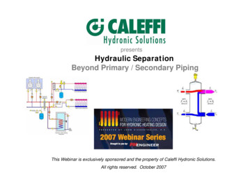
presentsHydraulic SeparationBeyond Primary / Secondary PipingThis Webinar is exclusively sponsored and the property of Caleffi Hydronic Solutions.All rights reserved. October 2007
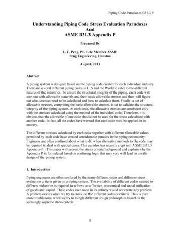
Modern compact boilers have much higher flow resistance than cast iron boilers.If they are simply substituted for cast iron boiler problems are likely to develop, mostnotably interference between simultaneously operating circulators.condensing/modulatingboilerzoned distribution system
The solution to this problem is hydraulic separation. In short,preventing flow in one circuit from interfering with flow in another circuit.In systems with hydraulic separation the designer can now think of each circuit as a“stand-alone” entity: Simplifying system analysis Preventing flow interferenceHydraulic separation is a new term tohydronic system designers in NorthAmerica.flow-checkvalvesecondary circuitPrimary / secondary piping, usingclosely spaced tees, is the bestknown form of hydraulic separationnow used inNorth spacedteesprimary loopflowDmaximum 4xD
The secondary circuit is “hydraulically separated” from the primary circuit by theclosely spaced tees.This concept can be extended to multiplesecondary circuits served by a commonprimary loop:high temperature secondary circuitmedium temperature secondary circuitprimary loopclosely spaced teeslow temperature secondary circuit
This configuration is more called a series primary/secondary system:Although hydraulic separation exists between allcircuits, so does an undesirable effect a drop in water temperaturefrom one secondary circuit to thenext when operatingsimultaneouslyhigh temperature secondary circuitmedium temperature secondary circuitprimary loopclosely spaced teeslow temperature secondary circuit
A parallel primary/secondary piping configuration provides the same watertemperature to each secondary circuit:This benefit is achieved at the expense ofmore complicated and costly piping.
In addition, both series and parallel primary/secondary systems require aprimary circulator.modulating / condensing boilerhaving high flow resistance#1boilercirculatorsecondary circuits#2#3#4modulating / condensing boilerhaving high flow resistanceprimarycirculatorsecondary r gvalvesThis adds to the installed cost of the system AND addhundreds, even thousands of dollars in operating cost over a typicalsystem life.
An example of primary loop circulator operating cost:Consider a system that supplies 500,000 Btu/hr at design load. Flow in theprimary loop is 50 gpm with a corresponding head loss of 15 feet (6.35 psipressure drop). Assume a wet rotor circulator with wire-to-water efficiency of 25is used as the primary circulator.The input wattage to the circulator can be estimated as follows:0.4344 f P 0.4344 50 6.35W 552watts0.250.25Assuming this primary circulator runs for 3000 hours per year its first yearoperating cost would be: 3000hr 552w 1kwhr 0.10 1st year cost 165.60 yr 1 1000whr kwhr
Assuming electrical cost escalates at 4% per year the total operating cost over a20-year design life is: (1 i )N 1 (1 0.04 )20 1 165.60 4, 931cT c1 i0.04 This, combined with eliminating the multi-hundred dollar installation cost of theprimary circulator obviously results in significant savings.
Beyond Primary / Secondary Piping How is it possible to achieve the benefits of hydraulicseparation and equal supply temperatures without thecomplexities and costs of a parallel system and primarycirculator?
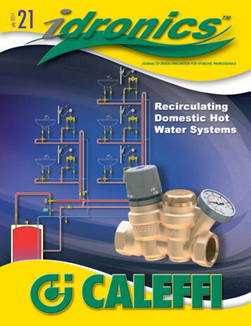
Some systems begin and end individual load circuits in the mechanical room:air ventshort, wide diameter headercirculators with internalcheck valves shownAequal supplytemperature toall loadssupply temperature sensor for boiler reset controllerclosely spaced tees (for hydraulic separation)distributioncircuitsB Header should be sizedfor max. flow velocity of 2feet per secondpurgingvavlesdrain valveboiler #1boiler #2 Each circuit mustinclude a check valve.The generous diameter of the header andclose spacing between supply and returnconnections results in a low pressure dropbetween points A and B. Each load circuit iseffectively hydraulically separated from theothers.
Another option is a specialized component called a hydraulic separator between theboiler and the load circuit:boilerhydraulicseparatorheatingloadThe low vertical velocity inside the separator produces minimal pressuredrop top to bottom and side to side. This results in hydraulic separationbetween the boiler circuits and load circuits.
Some hydraulic separators also provide air separation and sediment separation.To achieve these functions in a system using closely spaced tees additionalcomponents are required:
As the flow rates of the boiler circuit and distribution system changethere are three possible scenarios: Flow in the distribution system is equal to the flow in the boiler circuit. Flow in the distribution system is greater than flow in the boiler circuit. Flow in the distribution system is less than flow in the boiler circuit.Each case is governed by basic thermodynamic.
Case #1: Distribution flow equals boiler flow:port #1 port #3port #2 port #4 Very little mixing occurs because the flows are balanced.
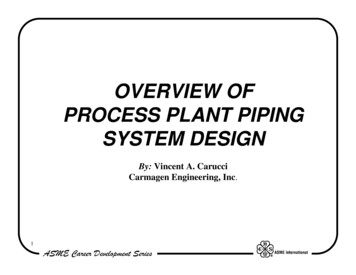
Case #2: Distribution flow is greater than boiler flow:The mixed temperature (T2) supplied to thedistribution system can be calculated with: ( f4 f1 )T4 ( f1 )T1 T2 f4 Where:f4 flow rate returning from distribution system (gpm)f1 flow rate entering from boiler(s) (gpm)T4 temperature of fluid returning from distribution system ( F)T1 temperature of fluid entering from boiler ( F)Mixing occurs within the hydraulic separator.
Case #3: Distribution flow is less than boiler flow:Heat output is temporarily higher than current system load.Heat is being injected faster than theload is removing heat.The temperature returning to the boiler (T3) canbe calculated with: ( f4 f1 )T4 ( f1 )T1 T2 f4 Where:T3 temperature of fluid returned to boiler(s) ( F)f1 flow rate entering from boiler(s) (gpm)f2, f4 flow rate of distribution system (gpm)T1 temperature of fluid entering from boiler ( F)T4 temperature of fluid returning from distribution system ( F)Mixing occurs within the hydraulic separator.
Use of a hydraulic separator alone does not prevent flue gas condensation under allcircumstances.To ensure such protection automatic mixing devices can be installed: The variable speed injection pump inpiped in parallel with the fixed speedcirculator The injection pump and fixedspeed circulator both require acheck valve
Sizing & Application:Hydraulic separators must be properly sized to provide proper hydraulic, air, and dirtseparation. Excessively high flow rates will impede these functions.Pipe sizeofhydr aulicseparato rMax fl owrat e( GPM)1”1. 2 5 ”1. 5 ”2”2. 5 ”3”4”6”1118264080124247485The header piping connecting to the distribution side of the Hydro Separator shouldbe sized for a flow of 4 feet per second or less under maximum flow rate conditions.
Hydraulic separators are an ideal way to interface multiple loads to aMultiple boiler system.
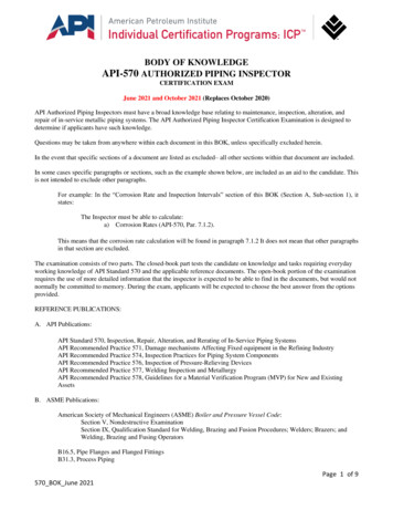
Example of Hydro Separator Installation in New System:Magna Steel Corporation - ConnecticutPhotos courtesy of Peter Gasperini - Northeast Radiant
Example of Hydro Separator Installation in Old System:Because hydraulic separators remove sediment from systems they’re ideal forapplications where new boilers are retrofit to old distribution systems.
Example of Hydro Separator Installation in Old System:Here is how the previous system was retrofitted.
Hydraulic Separation in “Micro-load” systems:The small insulated tank provides: Thermal buffering Hydraulic separation Air separation and collection Sediment separation and collection
Summary: Hydraulic separation, when properly executed, allowsmultiple, independently controlled circulators to coexist in asystem without interference. These devices eliminate the need for a primary loopcirculator, which reduces system installation and operatingcost.
Thank you for your participation.For additional questions, please contact:Caleffi Hydronic Solutions3883 W Milwaukee RdMilwaukee, WI 53208414.238.2360sales@Caleffi.comThis Webinar is exclusively sponsored and the property of Caleffi Hydronic Solutions.All rights reserved. October 2007
hydronic system designers in North America. Primary / secondary piping, using closely spaced tees, is the best known form of hydraulic separation now used in . heating load. To achieve these functions in a system usin