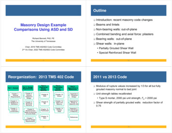
Transcription
OutlineMasonry Design ExampleComparisons Using ASD and SDRichard Bennett, PhD, PEThe University of Tennessee Introduction: recent masonry code changes Beams and lintels Non-bearing walls: out-of-plane Combined bending and axial force: pilasters Bearing walls: out-of-plane Shear walls: in-planeChair, 2016 TMS 402/602 Code Committee2nd Vic Chair, 2022 TMS 402/602 Code Committee Partially Grouted Shear Wall Special Reinforced Shear Wall-1--2-Reorganization: 2013 TMS 402 CodePart 1: GeneralChapter 1 –GeneralRequirementsChapter 2 –Notations &DefinitionsChapter 3 –Quality &ConstructionPart 2: DesignRequirementsChapter 4:GeneralAnalysis &DesignChapter 5:StructuralElementsChapter 6:Reinforcement,Metal Accessories& Anchor BoltsChapter 7:Seismic DesignRequirementsPart 3:EngineeredDesignMethodsPart 4:PrescriptiveDesignMethodsPart 5:Appendices &ReferencesChapter 8:ASDChapter 12:VeneerAppendix A– EmpiricalDesignChapter 9:SDChapter 13:Glass UnitMasonryAppendix B:Design ofMasonry infillChapter 10:PrestressedChapter 14:PartitionWallsAppendix C:Limit Designof MasonryChapter 11:AAC-3-2011 vs 2013 Code Modulus of rupture values increased by 1/3 for all but fullygrouted masonry normal to bed joint Unit strength tables recalibrated Type S mortar, 2000 psi unit strength, f′m 2000 psi Shear strength of partially grouted walls: reduction factor of0.75References-4-
CMU Unit Strength TablePartially Grouted Shear Wall FactorTMS 602 Table 29.3.4.1.2, Equation (9-21)Net areacompressivestrength of concretemasonry, psiType M or S MortarType N ,2502,6003,400Net area compressive strength of ASTMC90 concrete masonry units, psi (MPa)2,5003,2504,3502,7503,900---- 0.75 for partially grouted shear walls and 1.0 otherwiseFully grouted(Davis et al, 2010)Partially grouted(Minaie et al, 2010)MeanSt Dev1.160.170.900.26-5- 0.0035 clay masonry 0.0025 concrete masonry Masonry stress 0.8 Masonry stress acts over 0.8 0.9 flexure; 0.8 shear 21Beam and Lintel DesignStrength Design (Chapter 9) Allowable masonry stress: 0.45 Allowable steel stress 32 ksi, Grade 60 steel2.25 Minimum reinf: or4 3 Maximum reinf:0.8 0.8 No min and max reinforcement Allowable shear stress2.25-7-1.3,Allowable Stress (Chapter 8)Strength Design (Chapter 9)1. Assume value of (or ).Typically 0.85 0.95.2. Determine a trial value of/,Choose reinforcement.1. Determine , depth of compressivestress block,.2. Solve for3. Determine and ; steel stressand masonry stress. 30.776-6-Beam and Lintel DesignAllowable Stress (Chapter 8)0.901.161.5,3.4. Compare calculated stresses toallowable stresses.,.0.285 for CMUGrade 60 steel: 1.5 ksi,5. If masonry stress controls design,consider other options (such aschange of member size, orchange of ). Reinforcement isnot being used efficiently. 2 ksi,-8-0.007140.00952
Comparison of ASD and SDASD: Alternate Design MethodCalculate3Is2232,?NOFor Grade 60 steel,CMU 0.3123, 2YES,121Iterate. Use2 asnew guess and repeat.8 inch CMUd 20 in.1Compression controlsTension controls-9-Example: Beam- 10 -Allowable Stress Design: FlexureGiven: 10 ft. opening; dead load of 1.5 kip/ft; live load of 1.5 kip/ft; 24 in.high; Grade 60 steel; Type S masonry cement mortar; 8 in. CMU; ’ 2000 psiRequired: Design beamSolution:5.2.1.3: Length of bearing of beams shall be a minimum of 4 in.; typicallyassumed to be 8 in.5.2.1.1.1 Span length of members not built integrally with supports shall be takenas the clear span plus depth of member, but need not exceed distance betweencenter of supports. Span 10 ft 2(4 in.) 10.67 ft5.2.1.2 Compression face of beams shall be laterally supported at a maximumspacing of: 32 multiplied by the beam thickness. 32(7.625 in.) 244 in. 20.3 ft 120 / . 120(7.625 in.)2 / (20 in.) 349 in. 29.1 ft- 11 -Load1.5Weight of fully groutednormal weight: 83 psf.MomentDetermine0.083.2ft1.53.1745.1k ftAssume compression controls33.9.32in.20in.Check if compression controlsCalculate modular ratio,900- 12 -0.466. .0.31229000ksi900 2.0ksi9.32in.Compressioncontrols16.1
Allowable Stress Design: FlexureFind,Req’d area of steel0.90,19.31in. 7.625in.1116.1 0.90ksi0.4661Strength Design: Flexure1.94in.1.2Factored LoadWeight of fully groutednormal weight: 83 psf1.61.2 1.50.083.Factored MomentUse 2 - #9 (As 2.002ft1.6 1.5.62.6k ftin2).FindDepth of equivalentrectangular stress blockBars placed in bottom U-shaped unit, or knockout bond beam unit.Find,.20in. .20in.,Req’d area of steel.- 13 - 160 psi (parallel to bed jointsin running bond; fully grouted)Minimum Reinforcement Check:Cracking momentCheck 1.3.732in.732in. 160psi117.1k in. 9.76k ft1.31.3 9.76k ft12.7k ft78.5k ftMaximum Reinforcement Check:0.009520.88in.7.625in. 20in.- 15 -.3.78in.0.77in.- 14 -Check Min and Max ReinforcementSection modulus. 78.5 k-ft 70.6 k-ftUse 2 - #6 (As 0.88 in2).4.40Summary: Beams, FlexureDead Load (k/ft)(superimposed)Required As (in2)Live Load (k/ft)0.50.51.01.01.51.5ASDSD0.340.34 ( 1.5 ksi)0.260.26 (0.640.65 ( 1.5 ksi)0.500.52 ( 1.5 ksi)0.80 (ASD: Allowable tension controls for 0.5 k/ft and 1 k/ft.0.00577- 16 - 1.5 ksi)0.771.945.09 ( 1.5 ksi) 1.5 ksi)
Allowable Stress Design: ShearAllowable Stress Design: ShearDesign for DL 1 k/ft, LL 1 k/ft.Shear at reaction.11.56kCheck maxshear stress259.2psiReq’d steel stress./2 from face of supportDesign shear force4in.1.17ft.11.56k.9.02k.Shear stress.Allowable masonryshear stress.Suggest thatused, not .59.2psi.2.25Section 8.3.5.4allows design forshear at /2 fromface of supports.2.25 2000psi2 2000psi50.2psi0.5Determinefora spacing of 8 in./2 from face of supportDesign shear forceDesign masonryshear strength.0.034in.Use #3 stirrupsDetermine50.3psiso that no shear reinforcement would be required.Use a 32 in. deep beam if possible;will slightly increase dead load.23.5in.Strength Design: Shear.4in.1.17ft.2.250.8 2.25 7.625in. 20in.0.9 4 7.625in. 20in.16.00k12.50k2000psi4Check maxRequirement for shear at/2 from face of supportis in ASD, not SD, butassume it appliesSuggest thatnotto find- 19 -.- 18 -.16.00k.Design for DL 1 k/ft, LL 1 k/ftShear atreaction,beStrength Design: Shear.59.2psiOK8.9psi - 17 -.89.4psi12.28k.Req’d.0.5Determine . 12.50k OK,.Use #3 stirrups0.004in.so that no shear reinforcement would be required.be used,.21.82k0.28k.Determinefora spacing of 8 in.2000psi.20.4in.- 20 -Use invertedbond beam to getslightly greater .
Non-Bearing Partially Grouted WallsNon-Bearing Partially Grouted WallsOut-of-PlaneOut-of-PlanesAstfdabb’ effective compressive width per bar min{ , 6 , 72 in} (5.1.2)A. Neutral axis in flange:a. Almost always the caseb. Design for solid sectionB. Neutral axis in weba. Design as a T-beam sectionC. Often design based on a 1 ft widthMinimum reinforcement:No requirementsMaximum reinforcement:ASD: noneSD: Same as for beamsSteel Area 11120.0120.0210.0330.0471200.0110.0200.0310.044- 21 -- 22 -Example: Partially Grouted Wall ASDGiven: 8 in CMU wall; 16 ft high; Grade 60 steel,of 30 psf (factored)Required: Reinforcing (place in center of wall)Solution:. 0.45(2000psi) 900 psi32000 psi/ 16.1Determine 2000 psi; Lateral wind load6912Moment Example: Partially Grouted Wall ASDEquation / ValueIteration 1Iteration 2Iteration .07840.08100.08100.6990.7090.709(in.) . 576(in.2),1.80 x 106 psi29 x 106 psi,(in.)Assume compression controls3Check if compressioncontrols3. .- 23 -0.0910.3122.(in.)0.346in.Tension controlsUse # 4 @ 40 inches (As 0.060in2/ft)(close enough)- 24 -
Example: Partially Grouted Wall SDGiven: 8 in CMU wall; 16 ft high; Grade 60 steel,load of 30 psf (factored)Required: Reinforcing (place in center of wall)Solution:ASD vs SD: Flexural Members 2000 psi; Lateral wind. .11520FactoredMoment960 ASD calibrated to SD for wind and seismic loads When a significant portion of load is dead load, ASD willrequire more steel than SD When allowable masonry stress controls in ASD, designs areinefficient Advantage to SD, which is reason concrete design rapidlyswitched to SD about 50 years ago .FindSolve as solidsection .3.81in.Find3.81in.,.0.179in.0.0.0573.,Use #4 @ 40 inches (As 0.060in2/ft)- 25 -- 26 -ASD: Combined Bending andAxial Load Design MethodASD: Combined Bending andAxial Load Design MethodCalculate3IsIf2332622′?NOFor Grade 60 steel,CMU 0.312,1 ,Determination of1.0.452210.45Iterate. Use2 as newguess and repeat.1Compression controlsTension controls- 27 -0212,3YES,from cubic equation. 222tension controls; determineFor clay masonry,0.4532ksi29000ksi900700- 28 -,0.4532290009000.3680.312
Strength Design: CombinedBending and Axial LoadExample: Pilaster Design ASDGiven: Nominal 16 in. wide x 16 in. deep CMU pilaster; 2000 psi; Grade 60bar in each corner, center of cell; Effective height 24 ft; Dead load of 9.6 kips andsnow load of 9.6 kips act at an eccentricity of 5.8 in. (2 in. inside of face); Factoredwind load of 26 psf (pressure and suction) and uplift of 8.1 kips ( 5.8 in.);Pilasters spaced at 16 ft on center; Wall is assumed to span horizontally betweenpilasters; No ties.Required: Determine required reinforcing using allowable stress design.Solution: 220.80.8Is?For CMU, Grade 60 steel0.547 5.8 inYES2.0 inNO,Inside 0.8 0.8, 1800 ksi 16.1xLoadTension controlsCompression controlsLateral Load 0.6(26psf)(16ft) 250 lb/ft 11.8 in- 29 -- 30 -Example: Pilaster Design ASDExample: Pilaster Design ASDWeight of pilaster:Weight of fully grouted 8 in wall (lightweight units) is 75 psf. Pilaster islike a double thick wall. Weight is 2(75psf)(16in)(1ft/12in) 200 lb/ftUsually the load combination with smallest axial load and largest lateralload controls. Try load combination of 0.6D 0.6W to determinerequired reinforcement and then check other load combinations.The location and value of maximum moment can be determined from:0.6D 0.6W0.6 9.6k0.6 8.1k0.9k0.9k 5.8in.5.2k in.Top of pilasterLocation ofmaximum momentMaximummoment. .143.1in. . .28Vertical SpanningCalculateIf20 or, moment at topmeasured down from top of pilaster2- 31 -.Find axial force at this point. Include weight of pilaster (200 lb/ft).0.9k0.6 0.20Design for143.1in. 2.3 k,- 32 -. 218 k-in.2.3k218k in.
Example: Pilaster Design ASDExample: Pilaster Design ASDAssume compression controls; Determine33.Equation / Value . .Iteration 2),DetermineIteration 2(in.).Iteration 10254Tension controls0.312,(in.)2(in.)Try 2 - #5, 4 total, one in each cell- 33 -- 34 -Example: Pilaster Design ASDExample: Pilaster Design ASDf’m 2000 psif’m 1500 psiD 0.75(0.6W) 0.75SP 15.3kM 16.8k-ftD SP 19.2kM 9.25k-ftD 0.6WP 7.1kM 19.2k-ft0.6D 0.6WP 2.3kM 18.2k-ft- 35 -- 36 -
Example: Pilaster Design SDExample: Pilaster Design SDGiven: Nominal 16 in. wide x 16 in. deep CMU pilaster; 2000 psi; Grade 60bar in each corner, center of cell; Effective height 24 ft; Dead load of 9.6 kips andsnow load of 9.6 kips act at an eccentricity of 5.8 in. (2 in. inside of face); Factoredwind load of 26 psf (pressure and suction) and uplift of 8.1 kips ( 5.8 in.);Pilasters spaced at 16 ft on center; Wall is assumed to span horizontally betweenpilasters; No ties.Required: Determine required reinforcing using strength design.Solution:2.0 inxLoadLateral Load (26psf)(16ft) 416 lb/ft0.9 9.6k1.0 8.1k0.54k0.54k 5.8in.3.1k in.At top of pilaster:.Find location ofmaximum momentMaximummoment. .0.54k- 37 -.0.9 0.20143.7in. 2.7 kips, .11.8in. .1.50in. ,,. .0.57in.Try 2 - #5, 4 total, one in each cell- 39 - .- 40 -2.69k 361 k-in.Example: Pilaster Design SDDetermine required area of steel (assuming one layer).- 38 -Example: Pilaster Design SDDetermine143.7in.,Design for11.8in. .Find axial force at this point. Include weight of pilaster. 11.8 inDetermine.Vertical SpanningInside 5.8 in0.9D 1.0W361k in.
Example: Pilaster DesignASD vs SD: Pilaster DesignSimilar behavior to before ASD and SD close when allowable tension stress controls ASD more conservative when allowable masonry stresscontrols Less reinforcement required with SD due to small dead loadfactor SD design easier as steel has generally yielded Advantage to SD- 41 -- 42 -Design: Bearing Walls – OOP LoadsAllowable Stress(Chapter 8) No second-orderanalysis required No maximumreinforcement limits Use previous designprocedureStrength Design (Chapter 9) Second order analysis required Slender wall procedure Moment magnification Second-order analysis Need to check maximumreinforcement limits Need to check deflectionsStrength Design Procedure Assumes simple support conditions.Assumes midheight moment is approximately maximum momentAssumes uniform load over entire heightValid only for the following conditions: 0.05No height limit0.20 height limited byMoment:Deflection:factored floor loadfactored wall load- 43 -30- 44 -
Strength Design ProcedureStrength Design ProcedureSolve simultaneous linear equations: Cracking Moment: Cracked moment of inertia:Depth to neutral axis:.0.007Deflection LimitCalculated using allowable stress load combinations- 45 -- 46 -Example: Wind Loads ASDRequired: ReinforcementD 500 lb/ftLr 400 lb/ftW -360 lb/ft2.67 ftGiven: 8 in. CMU wall; Grade 60 steel; Type S masonrycement mortar; 2000 psi; roof forces act on 3 in.wide bearing plate at edge of wall.Example: Wind Loads ASDAssume 0.95,Cross-sectionof top of wall 0.080 in.2/ftTry #5 @ 48 in. (0.078 in.2/ft)Determine eccentricitye 7.625in/2 – 1.0 in. 2.81 in.wall weight is 38 psf for48 in. grout spacing32 psf0.77818 ft.0.084Find momentat top of wallEstimate reinforcement.0.6 0.5Find force at top of wallFind force atmidheightSolution: Check 0.6D 0.6W0.084.ft.(kip/ft)0.360.6 0.040ksf 2.67ftFind momentat midheightLoad Comb.0.69ft.(k-ft/ft)(kip/ft)0.364.0.6 0.032ksf.0.0840.049 0.753(k-ft/ft), (in2)0.6D 0.6W0.0840.364-0.0490.7530.068D 0.6W0.2840.751-0.0020.7770.059Use #5 @ 48 in. (0.078 in.2/ft)Although close to #5 @ 56 in. (0.066in.2/ft), a wider spacing also reduces wall weight- 47 -- 48 -
0.312; 1.19in.2. Assume masonry controls.Determine .Since 0.478 in. 1.18 in.tension controls.3. Iterate to find ,.3.,.0.457in. 2For centered reinforcement,Iteration 1Iteration .1036(in.) 3 .Equation / Value 2.(k-ft/ft)0Required: ReinforcementSolution:Estimate reinforcement .1.30 0.24 in. 0.078 in.2/ft,Cross-sectionof top of wallTry #5 @ 48 in. (0.078 in2/ft),2(in.)D 500 lb/ftLr 400 lb/ftW -360 lb/ftDetermine eccentricitye 7.625in/2 – 1.0 in. 2.81 in.0.791- 49 -- 50 -Example: Wind Loads SDExample: Wind Loads SDSummary of Strength Design Load Combination Axial ForcesModulus of rupture: use linear interpolation between no grout and full grout(wall weight is 38 psf for 48 in. grout spacing)Ungrouted (Type S masonry cement): 51 psiFully grouted (Type S masonry cement): 153 psiLoad Combination0.9D 1.0W1.2D 1.0W 0.5Lr(kip/ft)(kip/ft)(kip/ft)0.9(0.5) 1.0(-0.36) 0.0900.9(0.038)(2.67 9) 0.3990.4891.2(0.5) 1.0(-0.36) 0.5(0.4) 0.4401.2(0.038)(2.67 9) 0.5320.97251psi153psiCommentary allows inclusion of axial load (9.3.5.4.4)Use minimum axial load (once wall has cracked, it has cracked)6.97 . Factored floor load; just eccentrically applied load Factored wall load; includes wall and parapet weight, foundat mid-height of wall between supports (9 ft from bottom)68psi:Cracking moment, - 51 -32 psf1.Given: 8 in. CMU wall; Grade 60 steel; Type S masonrycement mortar; 2000 psi; roof forces act on 3 in.wide bearing plate at edge of wall. 32.67 ftSample Calculations: 0.6D 0.6WExample: Wind Loads SD18 ftExample: Wind Loads ASD.0.581. Wall properties determined from NCMA TEK 14-1B SectionProperties of Concrete Masonry Walls- 52 -.
Example: Wind Loads SDExample: Wind Loads SDFind16.1Modular ratio,Depth toneutral axis, factored moment at top of wall.is the moment at the top support of the wall. It includeseccentric axial load and wind load from parapet. factored out-of-plane load on parapet0.334in. height of parapetCracked moment of inertia,.16.1 0.077516.8.0.090.3.812in. 0.334in.ft.0.093 .- 53 -- 54 -Example: Wind Loads SDExample: Wind Loads SDCompare to capacity (interaction diagram)Depth of stressblock,. . .0.270in.Designmoment,0.917.19. .0.07751.432 ,- 55 -.1.309. - 56 - .60ksi3.812in.
Example: Wind Loads SDExample: Wind Loads SDLoad Combination2nd Order /1st Order(kip-ft/ft)(kip-ft/ft)1.2D 1.6Lr 0.5W0.7991.7550.4551.0741.2D 1.0W 0.5Lr1.4161.5740.9001.0970.9D 1.0W1.3091.4320.9141.047OKCheck Deflections: Use ASD Load CombinationsLoad Combination(k/ft)(k/ft)D 0.6W0.6D 0.6W0.5 0.6(-0.36) 0.2840.6(0.5) 0.6(-0.36) 0.08438(2.67 9) 0.4430.6(0.443) 740.4260.007Deflection Limit:0.007 18ft- 57 -. .0.0393ftCheck Maximum Reinforcement: (Section 9.3.3.2) neutral axis is in face shell Load combination D 0.75L 0.525QE (9.3.3.2.1 (d))is just dead load 0.5 0.038(2.67 9) 0.943k/ft atio- 59 -1.51in.Example: Wind Loads SDDeflections, Sample Calculations: D 0.6WReplace factored loads with service loads.- 58 -Example: Wind Loads SD.12.0.00917.- 60 -0.00169OKOK
Bearing Walls: SD Summary ,Factored Loads Axial load: include wall weight Moment: include second-order ASD vs SD: Bearing WallsSlender wall Moment magnification Second-order analysis Cross-section properties: Material properties:,ASD and SD require approximately the same amount ofreinforcement for reasonably lightly loaded walls SD requires a second-order analysis and a check ofdeflections Advantage to ASDeffectsProcedures ,,, Interestingly OOP loading is where designers often use SD,,Capacity Interaction diagram Need to only obtain point(s) of interest Maximum reinforcement Shear- 61 -- 62 -Shear Walls: ShearAllowable Stress (Chapter 8)4.01.750.254.01.750.25Shear Walls: Maximum ReinforcementStrength Design (Chapter 9)1.750.53 2 Interpolate for 0.2550.25 1.00.2541.052- 63 -26Interpolate for 0.251.0 Provide boundary elements Boundary elements notrequired in certain cases OR Limit reinforcement Based on strain condition0.250.5Special Reinforced Shear WallsStrength Design (Chapter 9)Special reinforced shear walls having 1 and 0.050.84.0Allowable Stress (Chapter 8)1.02- 64 -
Shear Walls: Shear Capacity DesignSD Maximum ReinforcementYes3AND0.053: Geometrically symmetrical walls: Geometrically unsymmetrical wallsYesNoNo boundaryelementsrequiredAllowable Stress (Chapter 8)Design with TMS 402 Section 9.3.3.2.Area of flexural tensile reinforcement arearequired to maintain axial equilibrium underthe following conditionsA strain gradient corresponding toinmasonry andin tensile reinforcementAxial forces from loading combination D 0.75L 0.525QE .Compression reinforcement, with orwithout lateral restraining reinforcement,can be included.AND0.10NoDesign with Boundary Elements?Is1 ORSpecial Reinforced Shear WallsDesign boundaryelements per TMS402 Section 9.3.6.6.2Yes Is Seismic design load requiredto be increased by 1.5 forshear Masonry shear stressreduced for special wallsDetermine6Is?3YES, 121 12Compression controls, 0.8,,12Approximate0.801Assume tension controls1112Tension controls 2266NOSolve for ,,0.65Approximate requireddistributed reinforcement distributed reinforcement (in.2/ft)- 67 -Except need not begreater than 2.5 . (doublesshear)SD: Distributed Reinforcementfrom the quadratic equation133 - 66 -ASD: Distributed Reinforcement13Design shear strength,greater than shearcorresponding to 1.25(increases shear at least1.39 times) 1.5- 65 -- 68 -, No1?Ordinary reinforced walls: 1.5Intermediate reinforced walls: 3Special reinforced walls: 4CalculateStrength Design (Chapter 9)0.9
Example: Shear Wall ASDExample: Shear Wall ASDGiven: 10 ft high x 16 ft long 8 in. CMU shear wall; Grade 60 steel, TypeS mortar; ′ 2000psi; superimposed dead load of 1 kip/ft. In-plane0.5 (just less than 0.5)seismic load of 50 kips.Calculate ; for preliminary design purposes use full thickness of wall13Required: Design the shear wall; ordinary reinforced shear wallSolution: Check using 0.6D 0.7E load combination.0.7 50k 10ft 350k ft4200k ftSinceAxial load, Need to know weight of wall to determine . Need to know reinforcement spacing to determine wall weight Estimate wall weight as 45 psf Wall weight: 45psf 10ft 16ft1 k ft 16ft7.2k 23.2k0.6 0.7 0.27.2k0.530.53 23.2k134200k in. 4200k in. 12.3k632ksi612.3k12.3k192in.34200k in. 12.3k0.147- 69 -- 70 -Example: Shear Wall ASDExample: Shear Wall ASDCalculate required area of reinforcement ,121111210.14710.147 192in. 7.625in. 32ksi21 0.147 16.1111 0.147 32ksi 192in.2in.in.0.009340.112in.ftUsed equivalent thickness 3.57 in.(40 in. grout spacing)12.3kStressed to 93% ofallowableTry #5 @ 32 in. (0.120in.2/ft)Due to module; use 40 in. (0.093in.2/ft) for interior bars32 in.40 in.40 in.- 71 -40 in.12.3k192in.3tension controls. Solve quadratic equation.31192in.3192in.632 in.- 72 -0192in.600.0550
Example: Shear Wall ASDExample: Shear Wall ASDGiven: 10 ft high x 16 ft long 8 in. CMU shear wall; Grade 60 steel,′ 2000psi; #5 at 32in. ends; #5 @ 40in. interior; superimposed deadload of 1 kip/ft. In-plane seismic load of 50 kips.0.7 50k726in.Shear Stress:120in.192in.Shear Span:Required: Design for shearSolution: Net area is shown below2 1.25in. 192in.253,Max Shear:6 8in. 7.625in. 2.5in.253OK2000psi 0.7512Required: Design the shear wall; ordinary reinforced shear wallSolution: Check using 0.9D 1.0E load combination.500k ft0.9Estimate dNeed to know weight of wall to determine . Need to know reinforcement spacing to determine wall weight Estimate wall weight as 45 psf 0.90.20.80- 75 -2000psi0.2512300lb0.250.75726in.OK, depthof stressblock7.2k0.80 23.2k,,area ofsteel 18.6k,dist. steel,173in. 20.8173in.173in.2 18.6k 173in. 192in. 26000k in.0.9 0.8 2000psi 7.625in. 0.8 Wall weight: 45psf 10ft 16ft1 k ft 16ft7.2k 23.2k0.9 192in.2Axial load, 1.75Example: Shear Walls SDGiven: 10 ft high x 16 ft long 8 in. CMU shear wall; Grade 60 steel, TypeS mortar; ′ 2000 psi; superimposed dead load of 1 kip/ft. In-planeseismic load of 50 kips.0.5 (just less than 0.5) 83.8psi- 74 -Example: Shear Walls SD 414 1.75 0.625251.9psi- 73 -50k 10ft0.62522 0.625726in.Masonry Shear: 48.2psi,0.8 2ksi 7.625in. 3.96in.60ksi ,,0.6518.6k 0.90.460in. 12in.ft0.65 192in.0.460in.0.044 in. ftTry #4 @ 48 in. (0.050in.2/ft)- 76 -3.96in.
Example: Shear Walls SDExample: Comparison to ASDDesign Strength8005000.7 SD: #4 @ 48 in.700400ASD: #5 @ 32,40 in.Used equivalent thickness 3.39 in.(48 in. grout spacing)500300400Axial (kip)Axial (kip)600300Stressed to 94% ofdesign strength200100ASD: 6 - #5200SD: 5 - #41000-1000500100015002000250000Factored LoadsMoment (kip-ft)Balanced Point200400‐10060012001400- 78 -Example: Shear Walls SDExample: Shear Walls SDGiven: 10 ft high x 16 ft long 8 in. CMU shear wall; Grade 60 steel,′ 2000 psi; #4 at 48in.; superimposed dead load of 1 kip/ft. In-planeseismic load of 50 kips.120in.192in.Shear Span:Max Shear:,0.8Required: Design for shearSolution: Net area is shown below45345 8in. 7.625in. 2.5in.1000Moment (k‐ft)- 77 -2 1.25in. 192in.800685in.MasonryShear:45322 0.625685in.1.750.8 4 1.75 0.62556.2kip0.6252000psi 0.75OK91.9kip0.25685in.2000psi0.25 18600lb 0.75OK- 79 -- 80 -
Example: Shear Walls SDExample: Shear Walls SDSection 9.3.3.2 Maximum ReinforcementSince/1, strain gradient is based on 1.5 .Strainc/d, CMUc/d, Clay1.50.4460.53030.2870.36040.2320.297Shear reinforcement requirements in Strength Design Except at wall intersections, the end of a horizontal reinforcing bar needed tosatisfy shear strength requirements shall be bent around the edge verticalreinforcing bar with a 180-degree hook. At wall intersections, horizontal reinforcing bars needed to satisfy shearstrength requirements shall be bent around the edge vertical reinforcing barwith a 90-degree standard hook and shall extend horizontally into theintersecting wall a minimum distance at least equal to the development length. 0.446(188in.) 83.8 in. Calculate axial force based on 83.8 in.Include compression reinforcement 323 kipsAssume a live load of 1 k/ftD 0.75L 0.525QE (1k/ft 0.75(1k/ft))16ft 28 kipsOK- 81 -- 82 -Example: Shear Wall ASDExample: Shear Wall ASDGiven: 10 ft high x 16 ft long 8 in. CMU shear wall; Grade 60 steel, TypeS mortar; ′ 2000 psi; superimposed dead load of 1 kip/ft. In-planeseismic load of 50 kips.0.5Masonry Shear:Required: Design the shear wall; special reinforced shear wall1414441.750.251.75 0.6252000psi0.2512300lb726in.Solution: Flexural reinforcement remains the same (although ASCE 7 allows aload factor of 0.9 for ASD and special shear walls) Design for 1.5V, or 1.5(0.7)(50 kips) 52.5 kips 52.5k 726in. Maximum72.3psi83.8psiRequired steelstress(Section 7.3.2.6.1.2)Use #5 bars inbond beams.Determinespacing.OK72.3psi0.75,0.5 - 84 -59.7psi0.5,0.5 0.31in. 32000psi 192in.59.7psi 726in.Use #5 @ 16 in.- 83 -36.7psi21.9in.36.7psi
Example: Shear Wall ASDExample: Shear Wall ASDDue to closely spaced bond beams, fully grout wall.7.625in. 192in.Shear Area:52.5k1464in.Shear Stress:Wall weight:Dead load:Masonry Shear:1464in.35.9psi81psf 10ft 16ft13.0k1 k ft 16ft13.0k0.53Axial load:14144Required steelstress0.53 29.0kUse #4 bars inbond beams.Determinespacing.29.0k35.9psi1.0,0.50.5 0.20in. 32000psi 192in.0.8psi 1464in.1.751.75 0.6250.252000psi 0.2515300lb1464in.minimum{ one-third length, one-third height, 48 in. }192 . 120 .min,, 48 .min 64 . , 40 . , 48 .3335.1psi40 .- 86 -Example: Shear Wall ASDSection 8.3.4.4 Maximum ReinforcementRequirements only apply to special reinforced shear walls0.0007 in each directionNo need to check maximum reinforcement since only need to check if:0.002 14646 0.31Vertical: ρHorizontal: ρ ,max 0.0020.00127OK0.00127, 0.00070.00073.2Determine bar size for 40 in. spacing,524in.Maximum Spacing Requirements (7.3.2.6)4Prescriptive Reinforcement Requirements (7.3.2.6).2,Spacing determined by prescriptive requirements15.3kExample: Shear Wall ASD 0.8psi0.5 - 85 - 35.1psi0.00073 7.625 . 40 .- 87 -1 and/0.6250.05 ′ 0.05(2000psi)(1464in2) 146 kips Assume a live load of 1 k/ft Use #5 @ 40 in.An alternate is #4 @ 32 in.0.22 ./ 1.00.7 0.21.00.7 0.2 0.5 29k16k47.0kOK0.00082- 88 -
Example: Shear Wall ASDExample: Shear Walls SDGiven: 10 ft high x 16 ft long 8 in. CMU shear wall; Grade 60 steel, TypeS mortar; ′ 2000 psi; superimposed dead load of 1 kip/ft. In-plane0.5seismic load of 50 kips.If we needed to check maximum reinforcing, do as follows.16.1 2ksi2 60ksi260ksi2ksi16.10.00582Required: Design the shear wall; special reinforced shear wallSolution: Flexural reinforcement remains the sameFor distributed reinforcement, the reinforcement ratio is obtainedas the total area of tension reinforcement divided by . ForAssume 5 out of 6 bars in tension.5 0.31in.7.625in. 188in.0.00108 Shear capacity design: Design shear strength,corresponding to 1.25OK- 89 -- 90 -Example: Shear Walls SD For #4 @ 48 in., 1.25 Design for shear of 76.6 kips 552 k-ft;Example: Shear Walls SD 613 k-ft 766 k-ft;But wait, need to check load combination of 1.2D 1.0E 18.6 k; [1.2 0.2()] 1.3 30.1 k, 1.25 Design for shear of 88.6 kips Bottom line: any change in wall will changedesign requirement Often easier to just use Design for shear of 100 kips 2.5 , or 709 k-ft , 886 k-ftBut wait, Section 7.3.2.6 has maximum spacing requirements: min{1/3 length of wall , 1/3 height of wall, 48 in.} 40 in. Decrease spacing to 40 in. 778 k-ft, 1.25 972 k-ftDesign for shear of 97.2 kips- 91 -, greater than shear- 92 -, which will change 2.5 2.0 .
Example: Shear Walls SDShear Area:(6 - #4 bars)2 1.25in. 192in.,Max Shear:0.8453453Example: Shear Walls SD6 8in. 7.625in. 2.5in.726in.22 0.6254MasonryShear:726in.2000psi 0.7597.4kipOptions: Design for shear from 1.25 97.2 kipsto 2100 psi,99.8 kips Increase, requires a unit strength of 2250 psi Grout more cells1.750.254 1.75 0.62599.0kipRequiredSteelStrength:726in.100k0.8 0.75,0.5Determinespacing:Use #5 bars2000psi 0.5 0.31in.0.25 18600lb99.0k67.7k0.5,60ksi 192in.67.7k26.4in.Use #5 at 24 in. o.c.- 93 -- 94 -Example: Shear Walls SDExample: Shear Walls SDMaximum reinforcement 0.446(188in.) 83.8 in. Calculate axial force based on Since Include compression reinforcement 1, 83.8 in. (#4 @ 40 in.) Section 9.3.6.5: Maximum reinforcement provisions of 9.3.3.5 do notapply if designed by this section (boundary elements) Special boundary elements not required if:0.100.05 1.5geometrically symmetrical sectionsgeometrically unsymmetrical sectionsAND 298 kips1 OROK Assume a live load of 1 k/ft D 0.75L 0.525QE 23.2kip 0.75(16 kip) 35.2 kipsFor our wall,0.10- 95 - 3AND10.10 2ksi 1464in.- 96 -293k3OK
Example: Shear Walls SD Prescriptive Reinforcement Requirements 0.0007 in each direction 0.002 totalASD vs SD: Shear Walls SD provides significant savings in overturning steel Most, if not all, steel in SD is stressed to fy. Stress in steel inASD varies linearly Vertical: 6(0.20in2)/1464in2 0.00082 Horizontal: 5(0.31in2)/[120in(7.625in)] 0.00169 Total 0.00082 0.00169 0.00251OK- 97 - SD generally requires slightly less shear steel Advan
Chair, 2016 TMS 402/602 Code Committee 2nd Vic Chair, 2022 TMS 402/602 Code Committee-2-Outline Introduction: recent masonry code changes Beams and lintels Non-bearing walls: out-of-plane Combined bending and axial force: pilasters Bearing walls: out-of-p