Transcription
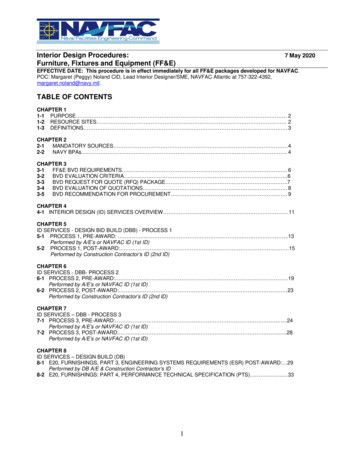
Published by :http://www.ijert.orgInternational Journal of Engineering Research & Technology (IJERT)ISSN: 2278-0181Vol. 5 Issue 08, August-2016Product Design and Development of Wheel Hubfor an All-Terrain Vehicle (ATV)Basavaraj SajjanAdithya ParthasarathyDept. of Mechanical EngineeringNitte Meenakshi Institute of TechnologyBangalore, 560064,Karnataka,IndiaDept. of Mechanical EngineeringNitte Meenakshi Institute of TechnologyBangalore, 560064, Karnataka, IndiaSai Kiran PVarun Kumar K NDept. of Mechanical EngineeringNitte Meenakshi Institute of TechnologyBangalore, 560064,Karnataka,IndiaDept. of Mechanical EngineeringNitte Meenakshi Institute of TechnologyBangalore, 560064, Karnataka, IndiaAbstract - Utilizing the Concept of Product Design andDevelopment in order to Design, analyse, manufacture and test awheel hub for an All Terrain Vehicle (ATV). Using FiniteElement Analysis as a method for reduction of cost in terms ofmaterial and manufacturing, we compared the results ofdifferent designs with different materials and selected theoptimum combination for manufacturing. Commercial vehicleindustry is focusing on bringing quality products at competitivecosts. While product weight has got a direct impact on the costof the component, it also has an impact in the operating profitsin case of a commercial vehicle. This project explains the use ofthe design and development of hub, the result of this project isthat proposed hub which uses aluminium 6061 T6 as thematerial is approximately 35% less weight than the EN8 MildSteel hub. The designed hub was effectively used in our ElectricATV which was subsequently approved by the panel judges ofthe SAE BAJA 2015. Based on the outputs obtained from theprevious design, new practical designs were generated and FEanalysis was carried out for the optimized design to verify thestrength of the hub. This optimized material resulted in weightsaving of the wheel hub without affecting the functionalrequirement.components and needs very good material and design in lowcost and avoids failure. The three basic elements of a wheelare the hub, the spokes and the rim. Sometimes thesecomponents will be one piece, sometimes two or three. Thehub is the center portion of the wheel and is the part where thewheel is attached to the suspension through the wheel carrier(or knuckle). The spokes radiate out from the hub and attachto the rim. The rim is the outer part of the wheel that holds thetyre. A hub assembly contains the wheel bearing and hub tomount the wheel to vehicle. It is located between the brakerotor and axle.Keywords— Wheel hub; EN8 mild steel; style;Al6061 T6 I. INTRODUCTIONProduct design is conceptualization of an idea about aproduct and transformation of the idea into a reality. Totransform the idea into reality a specification about theproduct is prepared. This specification is prepared byconsidering different constraints such as production process,customer expectation, etc. In product design stage everyaspects of the product are analyzed. Also, the final decisionregarding the product is taken on the basis of the analysis.This decision can be any aspect related to the product, e.g.dimension and tolerances, type of material for everycomponents etc.This work is based on the design and analysis of front hubfor weight reduction and increase the strength of hub by thehelp of Nastran / Patran. The weight and dimension of the hubmust be as small as possible because of the un sprung weightwhich further reduce the rotational mass. Engineeringcomponent with optimum use of material and easymanufacturability is a direction where prior simulationthrough finite element method is found to be very useful.Wheel hub of car is one of the major and very importantIJERTV5IS080413II.METHODOLOGY OF PRODUCT DESIGNProduct design is one of the most important and sensitivefactor for an organization. Success or failure of the productdecides company’s business, market share and reputation. Soduring design stage various factors related to the productneeds to be addressed. Synthesis: Try to develop different alternativesConceptualization: Draw sketches in exact scale fordifferent alternativesAnalysis: Analysis different alternatives with respect tooperability, maintainability, inspection, assembling anddismantling issues, cost parameters, production methods,etc.Selection: Select the best alternativeBasic engineering: Prepare layout in exact scale, calculatestrength of components and select proper cost effectivematerial.Detail design: Prepare detail engineering drawing foreach componentPrototype: If option is there, then prepare prototype andtest itManufacturing: If prototype is not made, then followmanufacturing steps and solve manufacturing problemsand assembly problems, if any.Operation: collect feedback during actual operation ofthe new product. If any problem exists, try to providedesign based solution. Also, implement lessons in thefuture design.Product development: If any modification can be done,implement the same in the next generation product.www.ijert.org(This work is licensed under a Creative Commons Attribution 4.0 International License.)504
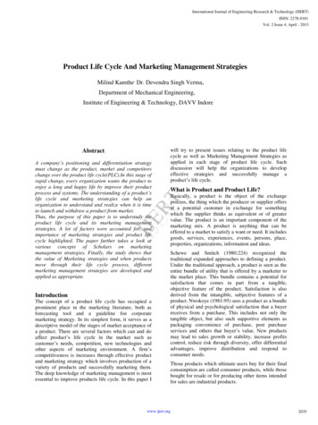
Published by :http://www.ijert.orgIII.International Journal of Engineering Research & Technology (IJERT)ISSN: 2278-0181Vol. 5 Issue 08, August-2016EN8 Mild SteelDESIGN CONSIDERATION Density: 7.85 g/cm3 The bolt pattern, determined the by the type of rim. Size of the rim should be considered. Selection of material must be strong enough to takethe weight of the car. Wheel bearing in the hub depends on ID and OD ofspindle coming out of hub. Tensile Yield Strength: 415MPa The Type of lug nuts or bolts should be decided. Poisson’s ratio: 0.27-0.30 Brinell Hardness number: 201 BHNWheel hub is highly street safety component which mustnot fail under the applied loading condition. The mainparameters for design of wheel hub assembly are: Loading condition Manufacturing process Material behaviourThe influence of these parameters are interactive somaterial fatigue behaviour will be change depending upon thewheel hub design and loading condition:Selection of materialAny engineering component has one or more functions (tosupport a load, to contain a pressure, to transmit heat, etc.). The designer must have an objective (to make it ascheap as possible, or as light as possible, or as safe aspossible or some combination of these) Should know the environment in which the productis being used. The component must carry the given load withoutfailure. It should function in a certain temperature range. The objectiveconstraints. Rockwell Hardness number: 93 Ra Ultimate Tensile Strength: 620 -740MPa Modulus of Elasticity : 190-210 GPa Melting Point: approx. 1500 C Thermal conductivity: 50.7 W/mKIV. DESIGNING A CAD MODELCATIA delivers the unique ability not only to model anyproduct, but to do so in the context of its real-life behaviour.Design in the age of experience. Systems architects, engineers,designers and all contributors can define, imagine and shapethe connected world. CAD model of Wheel Hub wasdeveloped in 3D modelling software CATIA V5 R20.Hubdesign mainly depends on Rim size, Bolt pattern and Weightof the Car. CAD model of Wheel Hub was developed in 3Dmodelling software CATIA V5 R20.Hub design MainlyDepends on Rim Size, Bolt Pattern and Weight of the Car. V.ANALYSIStoAnalysis was carried out using PATRAN as pre andpostprocessor and NASTRAN as solver.A. Material PropertyThe two materials considered for the wheel hub areAluminium 6061 T6 and EN8 Mild Steel. The propertiesof the materials are mentioned below:Patran is the world's most widely used pre/post-processingsoftware for Finite Element Analysis (FEA), providing solidmodelling, meshing, analysis setup and post-processing formultiple solvers including MSC Nastran, Marc, Abaqus, LSDYNA, ANSYS, and Pam-Crash. Patran provides a rich set oftools that streamline the creation of analysis ready models forlinear, nonlinear, explicit dynamics, thermal, and other finiteelement solutions. From geometry cleanup tools that make iteasy for engineers to deal with gaps and slivers in CAD, tosolid modeling tools that enable creation of models fromscratch, Patran makes it easy for anyone to create FE models.Meshes are easily created on surfaces and solids alike usingfully automated meshing routines, manual methods thatprovide more control, or combinations of both. Finally, loads,boundary conditions, and analysis setup for most popular FEsolvers is built in, minimizing the need to edit input decks.MSC Nastran is a multidisciplinary structural analysisapplication used by engineers to perform static, dynamic, andthermal analysis across the linear and nonlinear domains,complemented with automated structural optimization andembedded fatigue analysis technologies, all enabled by highperformance computing. MSC Nastran may be used to:mustbeachievedAluminium 6061 T6 Density: 2.7 g/cm3 Brinell Hardness number: 95 BHN Rockwell Hardness number: 40 Ra Ultimate Tensile Strength: 310 MPa Tensile Yield Strength: 276 MPa Modulus of Elasticity : 68.9 GPa Poisson’s ratio: 0.33 Fatigue Strength: 96.5 MPa Melting Point: 582 - 652 C Specific Heat Capacity: 0.896 J/g- C)IJERTV5IS080413subjectwww.ijert.org(This work is licensed under a Creative Commons Attribution 4.0 International License.)505
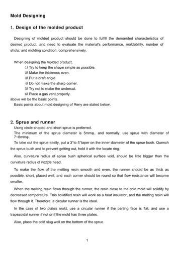
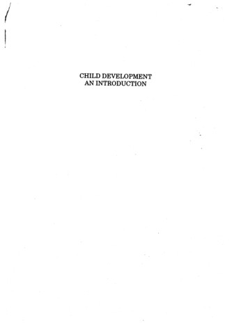
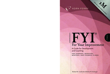
Published by :http://www.ijert.orgInternational Journal of Engineering Research & Technology (IJERT)ISSN: 2278-0181Vol. 5 Issue 08, August-2016 Virtually prototype early in the design process,saving costs traditionally associated with physicalprototyping. Remedy structural issues that may occur during aproduct’s service, reducing downtime and costs. Optimize the performance of existing designs ordevelop unique product differentiators, leading toindustry advantages over competitors.A. Static AnalysisTo observe maximum stress produce in Hubs, model issubjected to extreme conditions and static analysis is carriedout in Nastran/Patran. Hub has constraint at Rim mountings.Braking Torque and Bump Force was analytically calculatedand applied to Hub. A combined load of 3090N brakingTorque and 3g Bump Force were applied to the modelconsidering the longitudinal load transfer during brakingLOADING CONDITIONSBreaking Torque473.33N-mBump Force3g 3090NCalculations Braking Torque:Brake pedal force:1. The force applied on the pedal is assumed to be 294.3 N(30kgf)2. Pedal ratio 6:13. fmax force* pedal ratioμ Coefficient of friction between brake pad and disc(0.3)Re effective radius of the disc (97mm). Bump ForceMax velocity of Vehicle 60kmph.Mass of the vehicle 420kgFrom Newton’s second law of motion:F maF 420*3*gF 420*3*9.81F 12,360.6Ni.e., Force applied on each wheel is(12,360.6/4) (474.33/0.25) 5000N.RESULTSPARTICULARSALUMINIUMEN 8 MILD STEELLOAD APPLIED 2312372764151.21.75WEIGHT(kg)2.36.667A. Stress Induced: Material- Aluminum 6061 T6Insert pictureB. Stress Produced: Material – EN8 Mild Steel 294.3 * 6 1765.8 N(fmax force applied onto the master cylinder)Hence, P fmax/ (π/4) * d2(P hydrostatic pressure, d diameter of master cylinder’spiston)Fmax P * π/4) * D2 [by Pascal's Law](Fmax force acting on each piston of the caliper,D diameter of the piston in the caliper)By solving,4. Fmax fmax * (D / d)2 (1912.95)*(.029 / .019)2 4074.98 NTorque acting on the disc:T Fmax * μ * Re * number of pistons per calliper 4074.8 * 0.3 * 0.097 * 4 474.33 N-mWhere,IJERTV5IS080413www.ijert.org(This work is licensed under a Creative Commons Attribution 4.0 International License.)506
Published by :http://www.ijert.org.International Journal of Engineering Research & Technology (IJERT)ISSN: 2278-0181Vol. 5 Issue 08, August-2016STRESS DEVELOPED IN ALUMINIUMSTRESS DEVELOPED IN EN 8 MILD STEELVI.MANUFACTURING PROCESSRaw Material: Aluminium 60616061 is a precipitation hardening aluminium alloy, containingmagnesium and silicon as its major alloying elements.Originally called "Alloy 61S," it was developed in 1935. Ithas good mechanical properties and exhibits good weldability. It is one of the most common alloys of aluminium forgeneral purpose use.It is commonly available in pre-tempered grades such as6061O (annealed) and tempered grades such as 6061T6(solutionized and artificially aged) and 6061T651(solutionized, stress relieved stretched and artificially aged).A.Chemical ganeseMagnesiumChromiumZincTitaniumOther elementsAluminiumIJERTV5IS080413Minimum(by weight)Maximum(by weight)0.4%0.15%0.8%0.04%not more than %0.15%www.ijert.org(This work is licensed under a Creative Commons Attribution 4.0 International License.)98.56%507
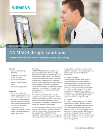
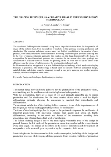
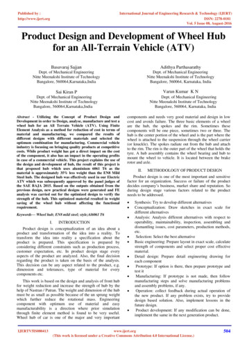
Published by :http://www.ijert.orgInternational Journal of Engineering Research & Technology (IJERT)ISSN: 2278-0181Vol. 5 Issue 08, August-2016B. Mechanical PropertiesVII.T6 temper 6061 has an ultimate tensile strength of atleast 42,000 psi (300 MPa) and yield strength of at least35,000 psi (241 MPa). More typical values are 45,000 psi(310 MPa) and 40,000 psi (275 MPa), respectively. Inthicknesses of 0.250 inch (6.35 mm) or less, it has elongationof 8% or more; In thicker sections, it has elongation of 10%.T651 temper has similar mechanical properties.The typical value for thermal conductivity for 6061T6 at77 F is around 152 W/m K. A material data sheet defines thefatigue limit under cyclic load as 14,000 psi (100 MPa) for500,000,000 completely reversed cycles using a standard RRMoore test machine and specimen. Note that aluminium doesnot exhibit a well-defined "knee" on its S-N graph, so there issome debate as to how many cycles equates to "infinite life".Also note the actual value of fatigue limit for an applicationcan be dramatically affected by the conventional deratingfactors of loading, gradient, and surface finish.WHEEL HUBVIII.Uses Bicycle frames and components.Many fly fishing reelsThe famous Pioneer plaque was made of thisparticular alloy.The secondary chambers and baffle systems infirearm sound suppressors (primarily pistolsuppressors for reduced weight and improvedmechanical functionality), while the primaryexpansion chambers usually require 174PH or 303stainless steel or titanium.The upper and lower receivers of many AR15 riflevariants.Many aluminium docks and gangways areconstructed with 6061T6 extrusions, and weldedinto place.Material used in some ultra-high vacuum (UHV)chambers.Many parts for remote controlled model aircraft,notably helicopter rotor components.C. Process Involved in the Manufacturing Turning Operation Turning Facing Milling Operation Drilling on Milling Machine Milling for weight reductionIJERTV5IS080413MANUFACTURED WHEEL HUBPRODUCT TESTING & VALIDATIONAcceleration TestAcceleration is measured as the time to complete a 30.48 m(100 ft.) or 45.72 m (150 ft.) flat, straight course from astanding start. The course surface may vary from pavement toloose dirt. The acceleration and the timing is determined withthe help of a device known as the Transponder whichmounted to the front right side of the vehicle.Hill climb or Traction TestThis event tests the vehicle’s relative ability to climb anincline from a standing start or pull a designated object, e.g.“eliminator skid”, vehicle, or chain, along a flat surface. Theorganizer will determine the hill height steepness and surfaceor object to be pulled.Brake TestThis test is mainly done to check the functionality of thebrakes. The organizer will determine if all the wheels lock ata time within the given Stopping Distance. Even if one of thewheels do not lock, the vehicle will not qualify for the finalEndurance event.www.ijert.org(This work is licensed under a Creative Commons Attribution 4.0 International License.)508
Published by :http://www.ijert.orgInternational Journal of Engineering Research & Technology (IJERT)ISSN: 2278-0181Vol. 5 Issue 08, August-2016POTENTIAL POTENTIAFAILURE L EFFECTSMODESOFFAILUREO D RPNRECOMMENDEDACTIONS1.Improperinstallationof axle nutA hub thatis fixedlooselywill causethe huband wheelassemblyto oscillatelaterallysidewise).Overtightening orlooselyfixing theaxle nut willresult inproblems asmentioned inthe effectscolumn5280Use torquewrench whiletightening theaxle nut toprevent itfrom beingunder-torquedor overtorqued.2.Overloading thevehicleOverloading a hubcreatessimilarconditionsas overtightenigthe hub.Due to theexcessiveweight,localizedheating ofthelubricanttakes place{betweenthe bearingrollers andbearingraces} .itcauses thebearings tofail orfatigue.Overloadinga vehicle i.e.,putting extraload on eachwheel than itcan tolerateor manage.73147Don'toverload thevehicle or thewheelsbeyond Itscapacity.Inspection ResultIX.S POTENTIALCAUSES OFFAILUREDFMEA FOR WHEEL HUBDesign Failure Mode and Effects Analysis (DFMEA) is usedto uncover design risk, which includes possible failure,degradation of performance and potential hazards. TheDFMEA is typically the first FMEA tool used in productdevelopment. When performed properly, there are manybenefits of DFMEA. X. CONCLUSIONWheel Hub has been designed for an ATV of mass440Kg and the maximum speed of 60kmph.The Designed Hub gives stability during rotation ofthe wheels.The Weight and Dimension of the Hub is such that itreduces the rotational mass.XI.ACKNOWLEDGMENTWe thank to Dr. H.C.Nagaraj, Principal and Managementof Nitte Meenakshi Institute of Technology, Bangalore, Indiafor motivating and providing research facilities at the 413Wong, j. Y. (2001). Theory of ground vehicles. New york, ny: johnwiley & sons, inc.Gillespie, thomas d; “fundamentals of vehicle dynamics”, warrendale,pa: society of automotive engineers inc., year 1999Milliken, william f & milliken, douglas l; “race car vehicle dynamics”,warrendale, pa: society of automotive engineers inc., year 1995Smith, carroll; “tune to win”, fallbrook, ca: aero publishers inc., year1978Finite element analysis of chervolet front hub with the help of inventer–vol.02, issue-02, (february, 2014) issn: 2321-1776.Design and analysis of wheel rim using catia and ansys by p.Meghashyam et al., ijaiem, issn no. 2319-4847.www.ijert.org(This work is licensed under a Creative Commons Attribution 4.0 International License.)509
A hub assembly contains the wheel bearing and hub to mount the wheel to vehicle. It is located between the brake rotor and axle. II. METHODOLOGY OF PRODUCT DESIGN . Product design