Transcription
Kuang-Hua Chang, Ph.D.MACHINING SIMULATION USINGSOLIDWORKS CAM 2018 SDCP U B L I C AT I O N SBetter Textbooks. Lower Prices.www.SDCpublications.com
Visit the following websites to learn more about this book:Powered by TCPDF (www.tcpdf.org)
Lesson 1: Introduction to SOLIDWORKS CAM1Lesson 1: Introduction toSOLIDWORKS CAM1.1Overview of the LessonSOLIDWORKS CAM (www.solidworks.com/product/solidworks-cam), powered by CAMWorks(www.camworks.com), is a parametric, feature-based virtual machining software offered as an add-in toSOLIDWORKS. Such an add-in module supports users to integrate design and manufacturing in oneapplication, connecting design and manufacturing teams through a common software tool that facilitatesproduct design in 3D solid model. By defining areas to be machined as machinable features,SOLIDWORKS CAM is able to apply more automation and intelligence into CNC (Computer NumericalControl) toolpath creation. This approach is more intuitive and follows the feature-based modelingconcepts of computer-aided design (CAD) systems. Because of this integration, you can use the same userinterface and solid models for design and later to create machining simulation. Such a seamlessintegration completely eliminates file transfers using less-desirable standard file formats such as IGES,STEP, SAT, or Parasolid. Hence, the toolpaths generated are on the SOLIDWORKS solid model, not onan imported approximation. In addition, the toolpaths generated are associative with SOLIDWORKSparametric solid model. This means that if the solid model is changed, the toolpaths are changedautomatically with minimal user intervention.One unique feature of SOLIDWORKS CAM is the AFR (automatic feature recognition) technology. AFRautomatically recognizes machinable features in solid models of native format or neutral file format;including mill features such as holes, slots, pockets and bosses; and turn features such as outside andinside diameter profiles, faces, grooves and cutoffs. This capability is complemented by interactivefeature recognition (IFR) for recognizing complex multi-surface features, as well as creating contain andavoid areas.Another powerful capability found in SOLIDWORKS CAM is its technology database, called TechDBTM,which provides the ability to store machining strategies feature-by-feature, and then reuse these strategiesto facilitate the toolpath generation. Furthermore, TechDBTM is a self-populating database, which containsinformation about the cutting tools and the machining parameters used by the operator. It also maintainsinformation regarding the cutting tools available on the shop floor. This database within SOLIDWORKSCAM can be customized to meet the user’s and the shop floor’s requirements. This database helps instoring the best practices at a centralized location in support of machining operations, both in computersand on the shop floors.We set off to discuss NC part programming and learn to use SOLIDWORKS CAM NC Editor and otherNC viewers to review and verify the NC part program or G-code. With the basic understanding of NCpart programming, we then start the main topic of the book: virtual machining simulation. We discuss thetopic by exploring and learning capabilities offered by SOLIDWORKS CAM. The lessons and examplesoffered in this book are carefully designed and structured to support readers becoming efficient in using
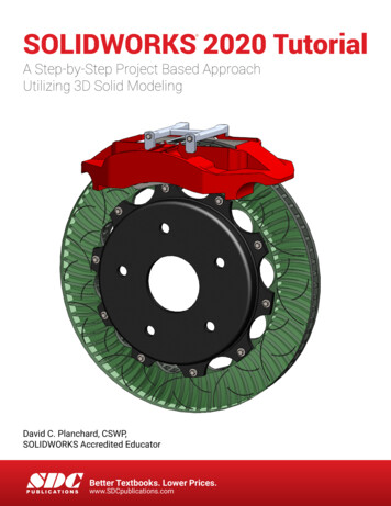
Lesson 1: Introduction to SOLIDWORKS CAM2SOLIDWORKS CAM and competent in carrying out virtual machining simulation for general machiningapplications.We assume that you are proficient with part and assembly modeling capabilities in SOLIDWORKS, havesome knowledge about NC part programming and the format and semantics of the G-code, andunderstand the practical aspects of setting up and conducting machining operations on CNC machines atthe shop floor. Therefore, this book starts with a brief review on NC part programming so that readerswill be able to read and revise, if necessary, the G-code generated from SOLIDWORKS CAM. We thenfocus on presenting virtual machining simulation using SOLIDWORKS CAM for toolpath and G-codegenerations. In addition to learning SOLIDWORKS CAM, we present two applications lessons, one formilling and one for turning operations, in which we load the G-code generated to CNC mill and lathe,respectively, and carry out physical machining operations at the shop floors. In these two lessons, wediscuss the important steps in transition from virtual machining to physical material cutting at the shopfloor, point out numerous practical aspects of CNC machining, and verify the accuracy of the G-code postprocessed by SOLIDWORKS CAM.Although SOLIDWORKS CAM is useful and powerful in support of most machining assignments,capabilities offered in the 2018 version are somewhat limited for machining freeform surfaces often foundin the die and mold machining operations. There are other third-party CAM modules fully integrated intoSOLIDWORKS that offer more capabilities than SOLIDWORKS CAM. At the end of the book (Lesson14), we introduce three such modules, including CAMWorks, HSMWorks (www.autodesk.com/products/hsm/overview), and Mastercam for SOLIDWORKS (www.mastercam.com/en-us), to show readersoptions available when it comes to machining parts that involve freeform surfaces.1.2Virtual MachiningVirtual machining is a simulation-based technology that supports engineers in defining, simulating, andvisualizing machining operations in a computer environment using computer-aided manufacturing (CAM)tools, such as SOLIDWORKS CAM. Working in a virtual environment offers advantages of ease inmaking adjustments, detecting errors and correcting mistakes, and understanding machining operationsthrough visualization of machining simulations. Once finalized, the toolpaths can be converted to G-codeand uploaded to a CNC machine at the shop floor to physically machine parts.The overall process of using SOLIDWORKS CAM for creating machining simulation, , as illustrated inFigure 1.1, consists of several steps: create design model (solid models in SOLIDWORKS part orassembly), choose NC machine and create stock, extract or identify machinable features, generateoperation plan, generate toolpath, simulate toolpath, and convert toolpath to G-code through a postprocessor. Note that before extracting machinable features, you must select an NC machine; i.e., mill orlathe, choosing tool cribs, selecting a suitable post processor, and creating a stock.The operation plan involves the NC operations to be performed on the stock, including selection of partsetup origin, where G-code program zero is located. Also included is choosing cutting tools, definingmachining parameters, such as feedrate, stepover, depth of cut, etc. Note that operation plans can beautomatically generated by the technology database of SOLIDWORKS CAM when a machinable featureis extracted or created manually beforehand. Users may make changes to any part of the operation plan,for instance, choosing a different cutting tool (also called cutter or tool in the book), entering a differentfeedrate, adjusting depth of cut, and so on. After an operation plan is complete, SOLIDWORKS CAMgenerates toolpath automatically. Users may carry out material removal simulation, step throughmachining toolpath, and review important machining operation information, such as machining time thatcontributes largely to the manufacturing cost.
Lesson 1: Introduction to SOLIDWORKS CAM3The design model (also called part, design part or target part in this book), which is a SOLIDWORKSpart representing the perfectly finished product, is used as the basis and starting point for all machiningoperations. Machinable features are extracted or created manually on the design model as references forindividual toolpaths. By referencing the geometry of the design model, an associative link between thedesign model and the stock is established. Because of this link, when the design model is changed, allassociated machining operations are updated to reflect the change.The following example, a block with a pocket and eight holes shown in Figure 1.2, illustrates the conceptof conducting virtual machining using SOLIDWORKS CAM. The design model consists of a base block(a boss extrude solid feature) with a pocket and eight holes that can be machined from a rectangular block(the raw stock shown in Figure 1.3) through pocket milling and hole drilling operations, respectively.Create Design Model Create a solid model, part or assembly, in SOLIDWORKSChoose NC Machine Choose an NC machine, mill or lathe, intended for the machining operations,choose a tool crib, and select a suitable post processor, Create stock, including shape, size and material typeExtract or CreateMachinable Features Use AFR to extract machinable features embedded in the solid model, such asholes, packets, bosses, etc.; or manually create machinable featuresGenerate OperationPlans Generate machining operation plans, including specific machining strategies,cutting tools, and machining parameters, such as feedrate, spindle speed, stepover,depth of cut, etc.Generate Toolpaths SOLIDWORKS CAM generates toolpathsSimulate Toolpaths Simulate machining operations or step through toolpaths Record machining timePost Process Convert toolpaths to G-code Verify G-codeFigure 1.1 Process of creating machining simulation using SOLIDWORKS CAMHoles (8)PocketFigure 1.2 Design model in SOLIDWORKSPart setup originStock (shadedrectangular block)Figure 1.3 Stock enclosing the design model
Lesson 1: Introduction to SOLIDWORKS CAM4A generic NC machine Mill-in. (3-axis mill of inch system) available in SOLIDWORKS CAM is chosento carry out the machining operations. For example, toolpaths for machining the pocket (both rough andcontour milling operations), as shown in Figure 1.4, can be generated referring to the part setup origin atthe top left corner of the stock (see Figure 1.3). Users can step through the toolpaths, for example, thecontour milling operation for cutting the pocket with tool holder turned on for display, as shown in Figure1.5. The material removal simulation of the same toolpath can also be carried out like that of Figure 1.6.Rough toolpath (shownin orange color)Contour toolpath(shown in blue color)Figure 1.4 Toolpath of the pocket milling operations1.3Figure 1.5 Step through toolpathSOLIDWORKS CAM PackagesSOLIDWORKS CAM offers two packages, Standard andProfessional. SOLIDWORKS CAM Standard supports youto quickly program individual milled parts andconfigurations without leaving the SOLIDWORKS 3D CADenvironment. You have full access to defining rules withinSOLIDWORKS CAM to create and build to your ownstandards. SOLIDWORKS CAM Standard also supportsTolerance-Based Machining (TBM).SOLIDWORKS CAM Professional builds on the capabilitiesof SOLIDWORKS CAM Standard with increasedprogramming capabilities. The additional features includeHigh-Speed Machining (HSM), configurations, assemblymachining, turning, and 3 2 programming to drive four- andfive-axis machines 1.Figure 1.6 The material removalsimulationPlease note that, as of 2018, SOLIDWORKS CAM offers 2½ axis (or 2.5 axis) milling capabilities. The3 2 programming mentioned above is misleading. 3 2 programing really should be called 2½ 2. It isnot 4 or 5 axis machining. All it does is use the 4th and 5th axis for positioning. They do not move oncepositioned and all subsequent operations are really just 2½ axis motion. Users have to use other thirdparty CAM modules, such as CAMWorks, HSMWorks, or Mastercam (please review Lesson 14), for fullthree axis or more simultaneous axes of motion.1Extracted from SOLIDWORKS website: www.solidworks.com/product/solidworks-cam
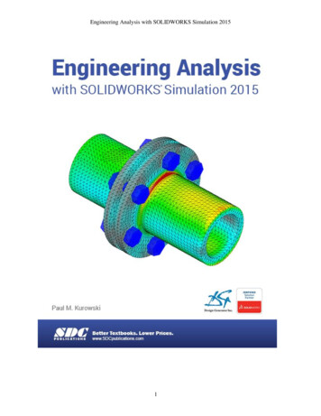
Lesson 1: Introduction to SOLIDWORKS CAM5Overall, the machining modules included in SOLIDWORKS CAM support 2.5 axis milling and 2-axisturning; that is: 2.5 axis mill: includes roughing, finishing, thread milling, face milling and single point cycles(drilling, boring, reaming, tapping) to machine prismatic features;2 axis turning: includes roughing, finishing, grooving, threading, cutoff and single point cycles(drilling, boring, reaming and tapping).All the above capabilities are discussed in this book and are illustrated using simple yet practicalexamples. In addition, SOLIDWORKS CAM supports machining of multiple parts in a single setup. Partsare assembled as SOLIDWORKS assembly, which includes parts, stock, clamps, fixtures, and jig table ina virtual environment that accurately represents a physical machine setup at shop floor. A multipartmachining example, as shown in Figure 1.7, with ten identical parts in an assembly will be introduced inLesson 7. Furthermore, machining features on multiple planes of parts mounted on the respective fourfaces of the tombstone, as shown in Figure 1.8, in a single setup is supported. More about multiplanemachining operations can be found in Lesson 8.ClampBoltJig tableFixtureRiserPartFigure 1.7 The material removal simulation of a multipart machining exampleToolRotary tablePartFixtureTombstoneFigure 1.8 Material removal simulation of the multiplane machining example
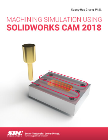
Lesson 1: Introduction to SOLIDWORKS CAM61.4User InterfaceThe overall design of SOLIDWORKS CAM user interface, as shown in Figure 1.9 that includes thelayout and windows, buttons, menu selections, dialog boxes, etc., is identical to that of SOLIDWORKSCAD. SOLIDWORKS users should find it is straightforward to maneuver in SOLIDWORKS CAM.As shown in Figure 1.9, the user interface window of SOLIDWORKS CAM consists of pull-downmenus, command buttons, graphics area, and feature manager window. An example file, Lesson 1 withToolpath.SLDPRT, is prepared for you to browse numerous capabilities and become familiar withselections, buttons, commands and options of SOLIDWORKS CAM user interface. This file (and allexample files of the book) is available for download at the publisher’s website(www.sdcpublications.com). You may review Section 1.5 for the detailed steps to bring the example intoSOLIDWORKS CAM.The graphics area displays the solid model and machining simulation on the solid model with which youare working. The pull-down menus provide basic solid modeling functions in SOLIDWORKS andmachining functions in SOLIDWORKS CAM. The command buttons of SOLIDWORKS CAM tab abovethe graphics area offer all the functions required to create and modify virtual machining operations in ageneric order. Major buttons include extract machinable features, generate operation plan, generatetoolpath, simulate toolpath, step through toolpath, and save CL file. When you move the mouse pointerover these buttons, a short message describing the function will appear. Some of the frequently usedbuttons in SOLIDWORKS CAM and their functions are summarized in Table 1.1 for your reference.Menu barand pulldown menuCommandmanager andcommandbuttonsSOLIDWORKS CAM tabFeature tree tabsHeads-up viewtoolbarGraphics areaResourcecenterFeature managerdesign treeStatus bar withshort messageStatus barReference triadFigure 1.9 User interface of SOLIDWORKS CAMUnit system
Lesson 1: Introduction to SOLIDWORKS CAM7Table 1.1 The major command buttons in SOLIDWORKS CAMButton SymbolNameDefine MachineFunctionAllows you to define the machine tool that the part willbe machined on, such as 3-axis mill.Define Coordinate Allows you to define a coordinate system and assign it asSystemthe Fixture Coordinate System for the active machine.Stock MangerAllows you to define the mill stock from a boundingbox, an extruded sketch or an STL file.Mill Part SetupAllows you to create Mill Part Setups that defines (1)tool orientation (or feed direction), (2) G-code programzero, and (3) the X direction of tool motion.ExtractInitiates automatic feature recognition (AFR) toMachinableautomatically extract solid features that correspond to theFeaturesmachinable features defined in the technology database(TechDBTM). The types of machinable featuresrecognized for mill and turn are different.SOLIDWORKS CAM determines the types of featuresto recognize based on the NC machine selected. Themachinable features extracted are listed in the featuremanager window under the SOLIDWORKS CAMfeature tree tab .GenerateGenerates operations automatically for the selectedOperation Planmachinable features. The operations and associatedparameters are generated based on rules defined inTechDBTM. An operation contains information on howthe machinable features are to be machined. Theoperations generated are listed in the feature managerwindow under the SOLIDWORKS CAM operation treetab.GenerateCreates toolpaths for the selected operations and displaysToolpaththe toolpaths on the part. A toolpath consists of cuttingentities (line, circle, arc, etc.) created by a machiningoperation that defines tool motion.Simulate Toolpath Provides a visual verification of the machining processfor the current part by simulating the tool motion and thematerial removal process.Step ThroughToolpathSave CL FilePost ProcessAllows you to view toolpath movements either onemovement at a time, a specified number of movementsor all movements.Allows you to save the current operation and associatedparameters in the technology database as CL (cutterlocation) data for future use.Translates toolpath and operation information into Gcode for a specific machine tool controller.
Lesson 1: Introduction to SOLIDWORKS CAM8There are four feature tree tabs on top of the feature manager window that are highly relevant in learningSOLIDWORKS CAM. The left most tab, FeatureManager design tree(see Figure 1.10), sets thedisplay to the SOLIDWORKS design tree (also called model tree or solid feature tree), which lists solidfeatures and parts created in SOLIDWORKS part and assembly in the feature manager window.The third tab from the right, SOLIDWORKS CAM feature tree tab(see Figure 1.11), shifts the displayto the SOLIDWORKS CAM feature tree, which lists machinable features extracted or manually createdfrom the solid model. The tree initially shows only the Configurations, Machine (for example, Mill-in inFigure 1.11), Stock Manager, Coordinate System, and Recycle Bin. The Machine entity indicates thecurrent machine chosen. You will have to select a correct machine before you begin working on a part. Ifyou click any machinable feature, an outline view of the machinable feature appears in the part in thegraphics area. For example, the sketch of the pocket appears when clicking Irregular Pocket1 in thefeature tree, as shown in Figure 1.11. Note that a symbol(called tool axis symbol) appears indicatingthe tool axis direction (or feed direction) of the current mill part setup.The tool axis symbolSketch of the pocketFigure 1.11 Selecting a machinable feature under theSOLIDWORKS CAM feature tree tabFigure 1.10 Solid features listed inthe feature manager window underthe FeatureManager design tree tabFigure 1.12 SOLIDWORKSCAM operation tree tabFigure 1.13 SOLIDWORKS CAM tools tree tab
Lesson 1: Introduction to SOLIDWORKS CAM9The second tab from the right, SOLIDWORKS CAM operation tree(shown in Figure 1.12), shifts thedisplay to the SOLIDWORKS CAM operation tree. After you select the Generate Operation Plancommand, the operation tree lists machining operations for the corresponding machinable features.Similar to SOLIDWORKS, right clicking a machining operation in the operation manager tree will bringup command options that you can choose to modify or adjust the machining operation, such as feedrate,spindle speed, and so on. Clicking any operations after selecting the Generate Toolpath command willbring up the corresponding toolpaths displayed in the part in the graphics area, like that of Figure 1.4.The rightmost tab, SOLIDWORKS CAM tools tree (shown in Figure 1.13), changes the display toSOLIDWORKS CAM tools tree. SOLIDWORKS CAM tools tree lists tools available in the tool cribschosen for the machining task.1.5Opening Lesson 1 Model and Entering SOLIDWORKS CAMA machining simulation model for the simple block example shown in Figure 1.2 has been created foryou. You may download all example files from the publisher’s website, unzip them, and locate the modelunder Lesson 1 folder. Copy or move Lesson 1 folder to your hard drive.Start SOLIDWORKS, and open model file: Lesson 1 with toolpath.SLDPRT. You should see a solidmodel file like that of Figure 1.2 appear in the graphics area.Entering SOLIDWORKS CAM from SOLIDWORKS is straightforward. You may simply click theSOLIDWORKS CAM feature tree tabor operation tree tabto browse respective machiningentities. You may right click any entity listed in the machining feature or operation tree to review ormodify the machining model. You may also choose options under the pull-down menu Tools SOLIDWORKS CAM to launch the same commands of those listed in Table 1.1 (and beyond) that supportyou to extract machinable features, generate an operation plan, and so on.If you do not see the SOLIDWORKS CAM feature tree or operation tree tab, you may have not activatedthe SOLIDWORKS CAM add-in module. To activate the SOLIDWORKS CAM module, choose fromthe pull-down menuTools Add-InsIn the Add-Ins dialog box shown in Figure 1.14, click SOLIDWORKS CAM 2018 in both boxes (ActiveAdd-ins and Start Up) and then click OK. You should see that SOLIDWORKS CAM tab appears abovethe graphics area like that of Figure 1.9 and the three SOLIDWORKS CAM tree tabs (feature, operation,and tool) added to the top of the feature manager window.If you still do not see SOLIDWORKS CAM tab appear above the graphics area, you may need to restartSOLIDWORKS to activate newly selected SOLIDWORKS CAM modules. Before going over thistutorial lesson, you are encouraged to check with your system administrator to make sure SOLIDWORKSand SOLIDWORKS CAM have been properly installed on your computer.Another point worth noting is that the auto saving option might have been turned on in SOLIDWORKSCAM by default. Often, it is annoying to get interrupted by this auto saving function every few minutesasking if you want to save the model. You may turn this auto save option off by choosing from the pulldown menuTools SOLIDWORKS CAM Options
Lesson 1: Introduction to SOLIDWORKS CAM10In the Options dialog box (Figure 1.15), select Disable Auto Saving under the General tab to turn it off.Then click OK.To browser an existing SOLIDWORKS CAM model, you may click any machinable features listed underthe SOLIDWORKS CAM feature tree tabto display the feature in the graphics area. For example, thepocket profile sketch like that of Figure 1.11 appears in the solid model after clicking Irregular Pocket1.You may also click any machining operation under SOLIDWORKS CAM operation tree tabtodisplay the toolpath of the selected operation. For example, clicking Rough Mill or Contour Mill displaystoolpaths on the solid model like those of Figure 1.4. You may step through the toolpath of an operation(for example, see Figure 1.5) by right clicking it and choosing Step Through Toolpath. You may rightclick an operation and choose Simulate Toolpath to simulate a material removal process of the operationlike that of Figure 1.6.1.6Extracting Machinable FeaturesMachining operations and toolpaths can be generated only on machinable features. A unique andappealing technical feature in SOLIDWORKS CAM is the automatic feature recognition (AFR)technology, which analyzes the solid features in the part and automatically extracts mill features such asholes, slots, pockets and bosses; and turn features such as outside and inside diameter profiles, faces,grooves and cutoff. The AFR technology helps in reducing the time spent by the designer to feed in datarelated to creating machining simulation.Figure 1.14 The Add-Ins dialog boxFigure 1.15 The Options dialog box
Lesson 1: Introduction to SOLIDWORKS CAM11A set of machinable features for milling and turning operations that can be extracted by AFR aresummarized in Appendix A. The associated machining strategies of individual machinable features can befound in Appendix B.The Extract Machinable Features commandinitiates AFR. Depending on the complexity of thepart, AFR can save considerable time in extracting 2.5 axis features, such as holes, pockets, slots, bosses,etc., either prismatic (with vertical walls) or tapered.AFR cannot recognize every single feature on complex parts and does not recognize features beyond 2.5axis. To machine these areas, you need to define machinable features manually using the interactivefeature recognition (IFR) wizard. For example, you may define a Multi Surface feature manually byselecting faces to be cut and faces to avoid in the design model. More on this topic will be discussed inthis book, for example, in Lesson 2: Simple Plate, and Lesson 6: Freeform Surface.1.7Technology DatabaseSOLIDWORKS CAM technology database, TechDBTM, is a self-populating database which contains allthe information about the machine, cutting tools and the parameters used by the operator, rules ofrepetitive NC operations (called strategy in SOLIDWORKS CAM) for the respective machinablefeatures. This database within SOLIDWORKS CAM can be customized easily to meet the user’s and theshop floor’s requirements. This database helps the best practices at a centralized location in the tool room;thus, it eliminates the non-uniformity in practicing virtual and physical machining operations.Using a set of knowledge-based rules, SOLIDWORKS CAM analyzes the machinable features anddetermines the machining process plan for a design model. In this approach, features are classifiedaccording to the number of possible tool approaching directions that can be used to machine them. Theknowledge-based rules are applied to assure that you get desired cutting operations. The rules thatdetermine machining operations for a respective machinable feature can be found in Appendix B, for bothmilling and turning operations.The technology database is shipped with data that is considered generally applicable to most machiningenvironments. Data and information stored in the database can be added, modified, or deleted to meet theuser’s specific needs in practice.1.8Tutorial ExamplesThere are fourteen lessons included in this book. In addition to the machining simulation example of thecurrent lesson, we go over two lessons discussing NC part programming before resuming our discussionon more machining simulation lessons. In Lesson 2, we discuss (or more like review) NC partprogramming, in which we review NC address codes, preparatory functions, and auxiliary functions,before going over examples of pocket milling, trajectory milling, profile milling, and canned cycles. InLesson 3, we introduce SOLIDWORKS CAM NC Editor, in which we learn to use the Editor to reviewand verify G-code.The next eight lessons, Lessons 4 to 11, illustrate step-by-step details of creating machining operationsand simulating toolpath capabilities in SOLIDWORKS CAM. We start in Lesson 4 with a simple plateexample, which provides you with a brief introduction to SOLIDWORKS CAM 2018, and offers a quickrun-through for creating a contour profile mill operation using a 3-axis mill.
Lesson 1: Introduction to SOLIDWORKS CAM12Lessons 5 through 9 focus on milling operations. We include examples of machining 2.5 axis featuresusing a 3-axis mill in Lesson 5, machining a freeform surface of a solid feature in Lesson 6, machining aset of identical parts in an assembly in Lesson 7, and machining features of parts on multiple planes usinga 3-axis mill with a rotary table in Lesson 8. In Lesson 9, we discuss tolerance-based machining (TBM),which leverages SOLIDWORKS dimensions, tolerance ranges and surface finish annotations to selectmachining strategies for operations and machine parts to the mean of asymmetric tolerances.Lessons 10 and 11 focus on turning operations. In Lesson 10, we use a simple stepped bar example tolearn basic capabilities in creating turning operations and understanding G-code generated bySOLIDWORKS CAM. In Lesson 11, we machine a similar example with more turn features to gain abroader understanding of the turning capabilities offered by SOLIDWORKS CAM.Lessons 12 and 13 discuss transition from virtual to physical machining, which is no small matter. InLesson 12, we present an application extracted from a student project that involves milling operations formachining robotic rover forearm members. SOLIDWORKS CAM was employed to conduct virtualmachining and toolpath generation for machining not only the forearm member but also a custom fixture.G-code generated by SOLIDWORKS CAM is then loaded to a HAAS CNC mill to machine the fixtureand part. In Lesson 13, we discuss a turning application, in which we turn a scaled baseball bat on aHAAS CNC lathe using G-code created from SOLIDWORKS CAM. The goal of these two lessons is tooffer readers a flavor of the role that SOLIDWORKS CAM is able to play in practical machiningassignments. Moreover, we point out important factors for you to consider before transporting the resultsof virtual machining to CNC machines at the shop floor to physically cut the part.In Lesson 14, we introduce third-party CAM modules that are fully integrated with SOLIDWORKS,including CAMWorks, HSMWorks, and Mastercam for SOLIDWORKS. In particular, we discuss millingoperations involving full three axis or more simultaneous axes of motion, which are not supported inSOLIDWORKS CAM in the 2018 version. Note that you may be able to download trial versions ofHSMWorks and Mastercam for SOLIDWORKS, install them on your computer, and go over Lesson 14.One thing we emphasize in this book is the verification of the G-code converted from machiningsimulation. Learning the menu selections and button clicking of SOLIDWORKS CAM for generatingmachining simulation is important. On the other hand, the simulation must lead to something useful at theshop floor. That is, the G-code converted from machining simu
and uploaded to a CNC machine at the shop floor to physically machine parts. The overall process of using SOLIDWORKS CAM for creating machining simulation, , as illustrated in Figure 1.1, consists of several steps: create design m