Transcription
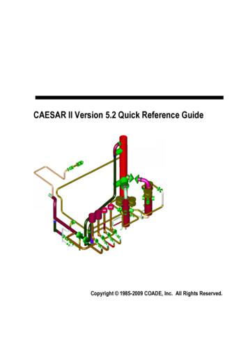
CAESAR II Version 5.2 Quick Reference GuideCopyright 1985-2009 COADE, Inc. All Rights Reserved.
CAESAR II Quick Reference Guide Table of ContentsCAESAR II Quick Reference Guide Version 5.20CAESAR II SoftwareCAESAR II Pipe Stress SeminarsSystem RequirementsTroubleshootingCAESAR II InterfacesPiping CodesRestraintsSetup File Directives ListList of MaterialsCAESAR II Intersection TypesCode StressesUS CodesInternational CodesNode Locations on BendsCAESAR II Verification and Validation ManualAdditional COADE Software Programs2233445781314151520283031
CAESAR II Quick Reference Guide2CAESAR II Quick Reference Guide Version 5.20The CAESAR II Quick Reference Guide is intended to aid users in quicklyidentifying needed information and to resolve common questions andproblems. This Reference Guide is distributed with each copy of thesoftware and users are urged to copy the Reference Guide asnecessary.Comments and suggestions concerning CAESAR II, the User Guide, orthe Quick Reference Guide are always welcome. Users with problems,questions, or suggestions can contact the COADE Development/Supportstaff at: techsupport@coade.com.CAESAR II SoftwareCAESAR II is an advanced PC based tool for the engineer who designs oranalyzes piping systems. CAESAR II uses input spreadsheets, on-linehelp, graphics, and extensive error detection procedures to facilitatetimely operation and solution.CAESAR II is capable of analyzing large piping models, structural steelmodels, or combined models, both statically and dynamically. ASME,B31, WRC, and rotating equipment reports combine to provide theanalyst with a complete description of the piping system’s behaviorunder the applied loading conditions. Additional technical capabilitiessuch as out-of-core solvers, force spectrum analysis (for water hammerand relief valve solutions), time history, and large rotation rod hangersprovide the pipe stress engineer with the most advanced computerbased piping program available today.CAESAR II is continuously enhanced to incorporate new technicalabilities, to provide additional functionality, and to modify existingcomputation procedures as the piping codes are updated. A completelist of the most recent changes to CAESAR II can be found in theChapter 1 of the User Guide. Users wanting software sales are urgedto contact the COADE Sales staff at:Phone: 281-890-4566E-mail: sales@coade.comFAX: 281-890-3301Web: http://www.coade.com/product overview.asp?varflag CAESARII
3CAESAR II Quick Reference GuideCAESAR II Pipe Stress SeminarsCOADE offers seminars periodically to augment the Engineersknowledge of CAESAR II and Pipe Stress Analysis. The general seminaris held in our Houston office and covers five days of Statics. Twiceyearly we also cover five days of Statics and three days of Dynamics.These seminars emphasize the piping codes, static analysis, dynamicanalysis, and problem solving.Custom seminars held at client locations are also available. Foradditional seminar details, please contact the COADE Support staff at:seminars @coade.com.System RequirementsCAESAR II requires Windows XP Professional or Windows Vista with aminimum graphic card capability of 1280x1024 resolution. However, formore efficient use of the software, higher graphics resolutions arenecessary. Usually any hardware capable of running these operatingsystems will be sufficient to run CAESAR II. For effective use of CAESAR II,COADE recommends as a minimum configuration:2 Ghz processor1 Gbytes of RAM1280x1024 graphics resolution or better256 Mbytes of video RAMWindows XP Professional or Windows VistaPlease note that Windows XP Home Edition and Windows Vista Home(Basic and Premium) is not supported.
CAESAR II Quick Reference Guide4TroubleshootingFor troubleshooting and problem solving issues, refer to the CAESAR IIFrequently Asked Questions (FAQ) located on the COADE Website. Toview the FAQ:(http://www.coade.com/product faq.asp?varflag CAESARII&varflagmaster .CAESAR II InterfacesThere are several external interfaces which allow data transfer betweenCAESAR II and other software packages. Users can access theseinterfaces via the Tools menu on the CAESAR II Main Menu.CADWorxrequires AUTOCADAUTOCADDXF OutputCOMPUTER VISIONmainframeINTERGRAPHmainframeCADPIPErequires AUTOCADISOMETmainframePDMSmainframePCFAlias formatUsers interested in these interfaces should contact COADE for furtherinformation. We anticipate other interfaces in the future keep usersupdated via the newsletter or revised documentation.
5CAESAR II Quick Reference GuidePiping CodesUse the table displayed below to identify the Piping Code, publicationand/or revision date.PIPING CODEPUBLICATION DATEREVISION DATEANSI B31.1(2007)December 7, 2006ANSI B31.3(2006)May 31, 2007ANSI B31.4(2006)October 20, 2006ANSI B31.4 Chapter IX(2006)October 20, 2006ANSI B31.5(2001)May 30, 2005ANSI B31.8(2007)November 30, 2007ANSI B31.8 Chapter VIII(2007)November 30, 2007ANSI B31.11(2002)May 30, 2003ASME SECT III CLASS 2(2007)July 1, 2008ASME SECT III CLASS 3(2007)July 1, 2008U.S. NAVY 505(1984)N/ACANADIAN Z662(6/2003)N/ACANADIAN Z662 Ch 11(6/2003)N/ABS 806SEPTEMBER 1993 ISSUE 1,N/ASWEDISH METHOD 1NDEDITION STOCKHOLM 1979N/ANDEDITION STOCKHOLM 1979N/A2SWEDISH METHOD 22ANSI B31.1(1967)N/ASTOOMWEZEN(1989)N/ARCC-M C(1988)N/ARCC-M D(1988)N/ACODETI(2001)June 2004NORWEGIAN(1999)N/AFDBR(1995)N/ABS7159(1989)N/A
CAESAR II Quick Reference Guide6PIPING CODEPUBLICATION DATEREVISION -13480(12/2006)Issue 9GPTC/Z380(2003)December 2007PD 8010 Part 1(2004)N/APD 8010 Part 5)N/A
7CAESAR II Quick Reference GuideRestraintsCAESAR II stores restraint information on 16 different restraint types.Restraint TypeAbbreviationAnchorATranslational Double ActingX,Y, or ZRotational Double ActingRX, RY, or RZGuide, Double ActingGUIDouble Acting Limit StopLIMTranslational Double Acting SnubberXSNB, YSNB, ZSNBTranslational Directional X, -X, Y, -Y, Z, -ZRotational Directional RX, -RX, RY, etc.Directional Limit Stop LIM, -LIMLarge Rotation RodXROD, YROD, ZRODTranslational Double Acting BilinearX2, Y2, Z2Rotational Double Acting BilinearRX2, RY2, RZ2Translational Directional Bilinear-X2, Y2, -Y2, etc.Rotational Double Acting Bilinear-RX2, RY2, - RY2, etc.Bottom Out SpringXSPR, YSPR, ZSPRDirectional Snubber XSNB, -XSNB, YSNB, etc.
CAESAR II Quick Reference Guide8Setup File Directives ListThe following list represents the possible directives which can becontrolled by the user via the CAESAR II configuration file CAESAR.CFG.These directives can be changed by the user through the use of theCONFIGURE-SETUP program, accessed via Main Menu option #9.Directives are listed in groups corresponding to the configurationprogram's menu options.GEOMETRY DIRECTIVESCONNECT GEOMETRY THRU CNODES YES34MIN ALLOWED BEND ANGLE .5000000E 0136MAX ALLOWED BEND ANGLE .9500000E 0237BEND LENGTH ATTACHMENT PERCENT .1000000E 0138MIN ANGLE TO ADJACENT BEND PT .5000000E 0139LOOP CLOSURE TOLERANCE .1000000E 0142THERMAL BOWING HORIZONTAL TOLERANCE .1000000E-0392AUTO NODE NUMBER INCREMENT 1000000E 02109Z AXIS UPNO129USE PRESSURE STIFFENING DEFAULT65ALPHA TOLERANCE .5000000E-0133HANGER DEFAULT RESTRAINT STIFFNESS .1000000E 1349DECOMPOSITION SINGULARITY TOLERANCE .1000000E 1150BEND AXIAL SHAPE YES51FRICTION STIFFNESS .1000000E 0745FRICTION NORMAL FORCE VARIATION .1500000E 0047FRICTION ANGLE VARIATION .1500000E 0248FRICTION SLIDE MULTIPLIER .1000000E 0146ROD TOLERANCE .1000000E 0159ROD INCREMENT 2000000E 0158COMPUTATION CONTROL
9CAESAR II Quick Reference GuideCOMPUTATION CONTROLINCORE NUMERICAL CHECK NO60DEFAULT TRANSLATIONAL RESTRAINT STIFFNESS .1000000E 1398DEFAULT ROTATIONAL RESTRAINT STIFFNESS .1000000E 1399IGNORE SPRING HANGER STIFFNESS NO100MISSING MASS ZPA EXTRACTED101MINIMUM WALL MILL TOLERANCE .1200000E 02107WRC-107 VERSION MAR 79 1B1/2B1119WRC-107 INTERPOLATION LAST VALUE120INCLUDE INSULATION IN HYDROTEST NO147AMBIENT TEMPERATURE 70.00135BORDER PRESSURE NONE136COEFFICIENT OF FRICTION 0.140INCLUDE SPRING STIFFNESS IN FREE THERMALCASES NO141SIFs and STRESSESREDUCED INTERSECTION B31.1 POST 198032USE WRC329NO62NO REDUCED SIR FOR RFT AND WLTNO53B31.1 REDUCED Z FIX YES54CLASS 1 BRANCH FLEXIBILITYNO55ALL STRESS CASES CORRODED NO35ADD TORSION IN SL STRESS DEFAULT66ADD F/A IN STRESS DEFAULT67OCCASIONAL LOAD FACTOR .00000E 0041DEFAULT CODE B31.343B31.1 SUSTAINED CASE SIF FACTOR 100000E 0140ALLOW USERS BEND SIF NO52USE SCHNEIDERNO63YIELD CRITERION STRESS MAX 3D SHEAR108
CAESAR II Quick Reference Guide10SIFs and STRESSESUSE PD/4TNO64BASE HOOP STRESS ONNO57EN-13480 use in-plane /out-plane SIFNO133LIBERAL ALLOWABLE YES137STREE STIFFENING DUE TO PRESS NO138B31.3 WELDING/CONTOUR TEE MEET B16.9NO139IMPLEMENT B31.3 APPENDIX PNO144IMPLEMENT B31.3 CODECASENO145B31.3 Sec 319.2.3(c), SaxialNO146PRESSURE VARIATION IN EXPANSION CASEDEFAULT DEFAULT143USE FRP SIF YES110USE FRP FLEXIBILITY YES11BS 7159 PRESSURE STIFFENING DESIGN STRAIN121FRP PROPERTY DATA FILE CAESAR.FRP122AXIAL MODULUS OF ELASTICITY3200000E 07113RATIO SHEAR MOD : AXIAL MOD 2500000E 00114AXIAL STRAIN : HOOP STRESS1527272E 00115FRP LAMINATE TYPE THREE116FRP ALPHA .1200000E 02117FRP DENSITY .6000000E-01118EXCLUDE F2 FROM BENDING STRESS UKOOANO134FRP PROPERTIES
11CAESAR II Quick Reference GuidePLOT RIGID/BENDSLIGHTGREEN17NODES YELLOWYELLOW18STRUCTURELIGHTRED31DISPLACED SHAPEBROWN30STRESS LEVEL 5RED24STRESS LEVEL 4YELLOW25STRESS LEVEL 3GREEN26STRESS LEVEL 2LIGHTCYAN27STRESS LEVEL 1BLUE28STRESS LEVEL 1DARKBLUE29STRESS LEVEL 5.3000000E 0519STRESS LEVEL 4.2500000E 0520STRESS LEVEL 3.2000000E 0521STRESS LEVEL 2.1500000E 0522STRESS LEVEL 1.1000000E 0523
CAESAR II Quick Reference Guide12DATABASE DEFINITIONSSTRCT DBASE AISC89.BIN70VALVE & FLANGE CADWORX.VHD90EXPANSION JT DATABASE PATHWAY.JHD91PIPING SIZE SPECIFICATION ANSI88DEFAULT SPRING HANGER TABLE 1112SYSTEM DIRECTORY NAME SYSTEM123UNITS FILE NAME .ENGLISH.FIL124LOAD CASE TEMPLATE .LOAD.TPL142ENABLE ODBC OUTPUTNO128APPEND RE-RUNS TO EXISTING DATANO126ODBC DATABASE NAME NONE 127OUTPUT REPORTS BY LOAD CASEYES87DISPLACEMENT NODAL SORTINGYES89DYNAMIC INPUT EXAMPLE TEXTMAX94TIME HIST ANIMATEYES104OUTPUT TABLE OF CONTENTSON105INPUT FUNCTION KEYS DISPLAYEDYES106MEMORY ALLOCATED12NAUSER ID " "NADISABLE UNDONOMISCELLANEOUS COMPUTATIONS128
13CAESAR II Quick Reference GuideList of MaterialsThe CAESAR II Material Table contains 17 different isotropic materials.Properties and allowed temperature ranges for each isotropic materialare listed below.Material No. Material NameElasticModulusPoisson's Pipe DensityRatio(lb./cu.in)TemperatureRange ºF1Low Carbon Steel29.5 E60.2920.28993-32514002High Carbon Steel29.3 E60.2890.28009-32514003Carbon Moly Steel29.2 E60.2890.28935-32514004Low Chrome Moly Steel29.7 E60.2890.28935-32514005Med Chrome Moly Steel30.9 E60.2890.28935-32514006Austenitic Stainless28.3 E60.2920.28930-32514007Straight Chromium29.2 E60.3050.28010-32514008Type 310 Stainless28.3 E60.3050.28990-32514009Wrought Iron29.5 E60.3000.28070-325140010Grey Cast Iron13.4 E60.2110.2558070100011Monel 67% Ni/30% Cu26.0 E60.3150.31870-325140012K-Monel26.0 E60.3150.30610-325140013Copper Nickel22.0 E60.3300.33850-325140014Aluminum10.2 E60.3300.10130-32560015Copper 99.8% Cu16.0 E60.3550.322707040016Commercial Brass17.0 E60.3310.30610-325120017Leaded Tin Bronze 114.0 E60.3300.31890-3251200Additionally CAESAR II supports material types 18 or 19 for cut short andcut long cold spring elements. Material number 20 activates theCAESAR II Orthotropic Material Model (i.e., Fiber-glass reinforcedplastic pipe); the default coefficient of expansion is 12.0 E-6 in./in./ F.Material 21 indicates user-defined properties. Material numbers over100 are from the Material Database and include the allowable stressand other piping code data.
CAESAR II Quick Reference Guide14CAESAR II Intersection TypesThe table below displays intersection types used in CAESAR II.TypeB31.3 TypeNotes1 ReinforcedReinforced Fabricated TeeUsed to lower SIFsNot a fittingModified pipe2 UnreinforcedUnreinforced Fabricated Tee Routine intersectionNot a fittingModified pipeUsually the cheapest3 Welded TeeWelding TeeUsually size-on-sizeGoverned by B16.9Usually the lowest SIFUsually expensive4 SweepoletWelded-in Contour InsertSit-in fittingForged fittings on a pipe5 WeldoletBranch Welded on Fitting"Sit-on" fittingForged fittings on a pipe6 ExtrudedExtruded Welding TeeSeldom usedUsed for thick wall manifoldsExtruded from straight pipeSketch
15CAESAR II Quick Reference GuideCode StressesListed below are the Code Stress equations for the actual and allowablestresses used by CAESAR II. For the listed codes, the actual stress isdefined by the left hand side of the equation and the allowable stress isdefined by the right hand side. The CAESAR II load case label is alsolisted after the equation.Typically the load case recommendations made by CAESAR II aresufficient for code compliance. However, CAESAR II does notrecommend occasional load cases. Occasional loads are unknown inorigin and must be specified by the user.US CodesStressLongitudinal Pressure Stress - SlpSlp PD0/4tn code approximationSlp PDi2/(D02 - Di2) code exact equation CAESAR II defaultOperating Stress - unless otherwise specifiedS Slp Fax/A Sb torque NA(OPE)ASME SECT III CLASS 2 & 3B1 (Pmax Do )2tn B2MaZ1.5Shi Mc / Z f (1.25 Sc 0.25 Sh) Sh -Sl(SUS)(EXP)B1 * Slpmax B2 * (Ma Mb) / Z 1.8 Sh and 1.5 Sy (OCC)B31.1Sl Slp 0.75 i Ma / Z Sh(SUS)i Mc / Z f [ 1.25 (Sc Sh) - Sl ](EXP)Slp 0.75 iMa / Z 0.75 iMb / Z k Sh(OCC)
CAESAR II Quick Reference Guide16B31.1 (1967) and Navy Section 505Sl Slp sqrt(Sb2 4 St2) Sh22(SUS)sqrt( Sb 4 St ) f (1.25Sc 0.25Sh (Sh-Sl))(EXP)Slp sqrt(Sb2 4 St2)
CAESAR II Quick Reference Guide Table of Contents CAESAR II Quick Reference Guide Version 5.20 2 CAESAR II Software 2 CAESAR II Pipe Stress Seminars 3 System Requirements 3 Troubleshooting 4 CAESAR II Interfaces 4 Piping Codes 5 Restraints 7 Setup File Directives List 8 List of Materials 13 CAESAR II Intersection Types 14 Code Stresses 15 US Codes 15 International Codes 20 Node File Size: 519KBPage Count: 34

