Transcription
Three Phase Transformer ConnectionsWe receive many member requests for 3 phase service. This may be as much as theyknow until an engineer or electrician gets involved with the project. Single phase serviceis provided by one transformer with a secondary voltage of 120V, 120/240V or240/480V. There are many more options for serving 3 phase loads. The different optionsare listed below.1. 120/240V Delta three phase with two transformers2. 120/240V Delta three phase with three transformers3. 120/208V Y three phase (this configuration requires three transformers)4. 120/208V Y three phase with pad-mounted transformer5. 240/480V Delta three phase with two transformers6. 480V Delta three phase with two transformers7. 240/480V Delta three phase with three transformers8. 480V Delta three phase with three transformers9. 277/480V Y three phase (this configuration requires three transformers)10. 277/480V Y three phase with pad-mounted transformer11. 2400V Delta three phase12. 2400/4160V Y three phaseEach option will be explained in more detail including pictures on the following pages.There are many valid reasons that a member would request three phase service. Themember will be required to complete the Electric Load Requirements Form or providecomparable information for each three phase request. This provides documentation fromthe member for the voltage. It also provides Tri-County information to size transformers,service and meter.A few members and electricians have the mistaken idea that three phase service ischeaper than single phase service. This is based on the idea that the nameplate currentrating for a three phase device will be about a third of the nameplate current rating for asingle phase device. However, we meter energy (voltage x amps) instead of current(amps). A single phase device with the same rating as a three phase device will use thesame energy. For example, a 5HP single phase motor will use the same energy as a 5HPthree phase motor assuming they perform the same function and have the sameefficiency.1
1. 120/240V Delta Three Phase with Two TransformersThis is a very common configuration for service to small three phase loads. It is usuallycalled “V” phase or “B” phase installation. The “V” phase terminology comes from thenormal Y configuration for our distribution system. When only two transformers areused, it is an “Open Y” configuration on the primary side. Since the “Y” reflects thephase-to-ground contribution from three transformers, leave the bottom part of the “Y”off and a “V” is left with two transformers. The “B” phase terminology probably comesfrom REA construction standards. Two phase pole top assemblies are “B” units.The secondary side is connected in an “Open Delta” configuration. This is a 4-wireservice and the member receives three phase service. The voltage from any phase toanother phase is 240V. Single phase power is provided from a 120/240V single phasecenter-tapped transformer. This transformer is called the lighting transformer. The othertransformer is called the power transformer. No single phase load is connected to thepower transformer. The neutral is connected to the center tap on the lighting transformer.The voltage is 120V from the neutral to the outside taps on the lighting transformer. Thevoltage from the neutral to the third phase is undefined. This is the infamous “wild leg”and is typically 208V. It may also be called a “freak leg”.Recognizing this installation in the field is the easiest since this is the only way to hookup two transformers. You will not be able to determine if the secondary voltage is120/240V or 240/480V. You will be able to determine if it is 480V straight powerbecause neither transformer will be center-tapped.The drawing at right showsthe voltage diagram for thesecondary side. A240/480V installation withtwo transformers will looksimilar. A 480V straightpower installation will notuse the center tapconnection.The primary side is connected in an “Open Wye” configuration. This type of installationis often termed an “Open Wye-Open Delta” transformation. It is normally used wherethe largest motor is 20hp or less. This is just a guideline since 25 and 30hp motors willwork with an Open Wye-Open Delta configuration. Submersible pumps can causeproblems since they have a higher current draw than other motors and tend to be sizedcloser to capacity. This installation should also be limited to a total load of 50-75kW.The lighting transformer serves the entire single phase load. It also serves 58% of thethree phase load. The power transformer also serves 58% of the three phase load. Notethat the total percentage of three phase load from both transformers adds up to more than2
100%. Since the lighting transformer serves the single phase load in addition to part ofthe three phase load, it is usually larger than the power transformer.The drawing at right shows a typical wiringconfiguration. The transformer on the left isthe lighting transformer. It is the one with thecenter bushing (x2) tied to the neutral. Thetransformer on the right is the powertransformer. The center bushing is not used.Note that two bushings (x1 on the lefttransformer and x3 on the right transformer)are tied together. Together they serve onephase (b in this drawing). Also note that theneutral to c phase voltage is 208V. In actualsituations, the measured voltage may be 216217V instead of 208V. This is the wild legsince c phase is served by the power transformer.The picture below shows a typical installation without a transformer bracket. In this casethe right transformer is the lighting transformer. Two clues are used to tell you thatinformation. The first is the size. The right transformer is larger (size and capacity). Thesecond is the center bushing is connected to the neutral. The center bushing on the lefttransformer is not used.3
A transformer bracket is used for most installations today. The picture above shows anOpen Wye/Open Delta bank mounted on the transformer bracket. Clearly visible is thelocation to mount the third transformer if needed. When installed on a three phase line, itis common to connect the transformers to the outside phases.4
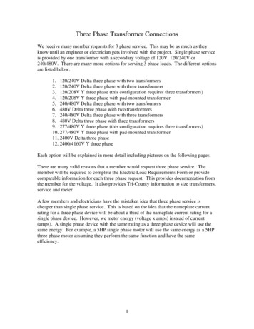
2. 120/240V Delta Three Phase with Three TransformersThis transformer configuration is used when the Open Wye-Open Delta configuration isnot adequate. It is known as a Wye-Delta configuration. It is no longer open since threetransformers are used instead of two. The secondary side is connected in a Deltaconfiguration. This is a 4-wire service and the member receives three phase service. Thevoltage from any phase to another phase is 240V. Single phase power is provided from a120/240V single phase center-tapped transformer. This transformer is called the lightingtransformer. The other two transformers are called the power transformer. No singlephase load is connected to the power transformers. The neutral is connected to the centerbushing on the lighting transformer. The voltage is 120V from the neutral to the outsidetaps on the lighting transformer. The voltage from the neutral to the third phase isundefined. This again is the “wild leg” or “freak leg” and is typically 208V.The drawing at rightshows the voltagediagram for the secondaryside. A 240/480Vinstallation with twotransformers will looksimilar. A 480V straightpower installation willnot use the center tapconnection.The lighting transformer should be sized to serve 2/3 of the single phase load and 1/3 ofthe three phase load. The two power transformers should be sized to serve 1/3 of thesingle phase load and 1/3 of the three phase load. It shows that this configuration is notefficient as the Wye-Wye configuration (option 3 from the list on Page 1) since the totaltransformer bank must be sized for 133% of the single phase load (2/3 1/3 1/3 1.33). It also has two other disadvantages over a Wye-Wye configuration.One disadvantage is feedback on the primary side when a primary phase is lost. Thethree transformers in this configuration form a closed loop on the secondary side. Whena primary phase is lost, the closed delta configuration will induce a voltage on theprimary side. This can cause problems with restoration and must be remembered by theserviceman. The induced voltage does not happen with an Open Wye-Open Deltaconfiguration since the secondary side does not have a closed loop. The induced voltagedoes not happen with a Wye-Wye configuration since the secondary side is configuredWye instead of Delta.A second disadvantage is ferroresonance. Ferroresonance is an occurrence of a nonstable high voltage set up due to the magnetizing impedance of the transformers matchingthe capacitance of the circuit under no-load or low load conditions. It occurs when a fuseis blown, a wire is broken or during single phase switching on a transformer with Delta5
connections on the low side or the high side. Ferroresonance can cause damage fromover-voltage and will usually cause a noticeable vibration in the transformers. Theproblem can be mitigated when all three phases are energized at the same time. It is alsomitigated by energizing the transformer under load or grounding the H2 bushing on theall three transformers on a temporary basis. Ferroresonance will not happen in an OpenWye-Open Delta configuration. It is very unlikely to occur in a Wye-Wye configuration.Neither has the closed secondary loop in the Wye-Delta configuration.The drawing at right shows a typicalwiring configuration. The transformer inthe middle is the lighting transformer. Itis the one with the center bushing (x2)tied to the neutral. It is normally themiddle transformer on the pole. Theother two transformers are the powertransformers. The center bushing is notused on these two. Note are twobushings (x1 on the left transformer andx3 on the right transformer) are tiedtogether on adjacent transformers.Together they serve one phase. This isthe way to determine if a three phasebank is Wye-Delta configuration insteadof a Wye-Wye. Also note that theneutral to c phase voltage is 208V. Thisis the wild leg since c phase is served by the power transformers.The picture below shows a typical installation. The middle transformer is a 50kVA whilethe other two are 37.5kVA. This is normal that the middle transformer be one size largerthan the other two. Note the jumper tying adjacent secondary bushings together. This ischaracteristic of a delta installation.6
7
3. 120/208V Y Three PhaseThis is a very common configuration for larger three phase loads. It is widely used inretail and office applications. This is a four wire service and the member receives threephase service. The voltage from any phase to another phase is 208V. This is differentthan the 240V between any two phases on a delta service. Many (maybe most) threephase motors have taps that allow them to be set for 208V or 240V. Those that do nothave taps will be set for 220V and can handle either voltage. Single phase power is only120V and is served from each transformer. For this reason the panel should be wired toserve single phase load evenly from each phase.The drawing at right shows thevoltage diagram for thesecondary side. A 277/480Vinstallation will look similar.The primary side is alsoconnected Wye. This type ofinstallation is often termed aWye-Wye transformation. It ispreferred over a 120/240VWye-Delta configuration forthe reasons stated in the previous section.Each transformer carries 1/3 of the single phase load and 1/3 of the three phase load.Stated another way, each transformer serves 1/3 of the total load.The drawing at right shows a typicalwiring configuration. The secondarywindings inside the transformer have to bechanged. The lead windings are “cutover”. This is the process of moving thelead from the x2 bushing to either x1 or x3as appropriate. When complete, thetransformer has both windings connectedfrom x1 to x3 (the two are in parallel).The voltage from x1 to x3 is now 120V.Note how the x2 bushing is not used onany transformer. In this drawing the x3bushing on each transformer is tied to theneutral. Each x1 bushing provides one ofthe phases. Adjacent bushings are not tied together like they are in a Delta configuration.The picture below shows a typical installation. There are three 100kVA transformers.They do not have a center bushing. Transformers purchased for 120/208V or 277/480Vwill not have a center bushing. This is one easy spotting feature of this type of8
transformer bank. The left bushing on each transformer is tied together and to theneutral. Each right bushing serves a phase.9
4. 120/208V Y Three Phase with Pad-Mounted TransformersThis is a common application to serve three phase loads where a pad-mountedtransformer is desired or needed. This is a four wire service and the member receivesthree phase service. The voltage from any phase to another phase is 208V. The size andsecondary voltage is typically painted on the cabinet face. The voltage diagram isidentical to the 120/208V diagram in the previous section. The typical transformer sizesare 112kVA, 225kVA, 300kVA, 500kVA, 750kVA, and 1000kVA. It is possible to get45kVA and 75kVA transformers but they are not as common because the cost is similarto the 112kVA transformer. Above 1000kVA, pad-mounted transformers will have ahigher secondary voltage such as 277/480V. In practice, it is uncommon to use atransformer larger than 300kVA for a 120/208V service.We have two standard pad sizes for a pad-mounted transformer. Up to a 500kVA padmounted transformer, an 8 foot x 8 foot pad is used. For a 750kVA to 2500kVA padmounted transformer, a 10 foot x 10 foot pad is used. Typically, the member orconstruction company is requested to provide the pad. They are already pouring concretefor the slab and flat work such as drives and sidewalks. A diagram of the pad needs to beprovided to the construction crews.The metering can be installed on the cabinet of the transformer if the service is for onlyone member. Current transformers (CT’s) will be placed around the secondary bushings.Control cable connects the CT’s to the meter. If multiple meters are needed such as at ashopping center, then the metering will be installed on the building.The member will be responsible for the installation of the service from the secondary lugsof the transformer to the building. The pad diagram shows the opening for the secondaryside. The member will need this information to determine the number and size ofconduits that need to be installed between the transformer and the building.Clearances need to be considered in the design process. Ten feet of clearance needs to bemaintained in front of the access doors for working clearance. The distance will allow aman to use a hot stick when working on the connections in the primary cabinet. Thedistance from the transformer to the building wall requires a minimum of 12 feet if thebuilding wall is anything less than a 3 hour fire rating. See the drawing below for otherclearance requirements.10
11
The drawing above shows a typical pad-mounted transformer. Looking at the FrontView, the primary side is on the left and the secondary side is on the right. The meterwould be mounted on the right side of the transformer. The HV & LV Detail show thetypical locations of the primary bushings (H1, H2, and H3 – circle 9). It also shows thetypical locations of the secondary bushings (X1, X2, and X3 – circle 10). Thetransformer nameplate is located in the secondary side.12
5. 240/480V Delta Three Phase with Two TransformersThis installation is very similar to the 120/240V Delta Three Phase with TwoTransformers. See Section 1 for a more complete description.13
6. 480V Delta Three Phase with Two TransformersThis installation is also very similar to the 120/240V Delta Three Phase with TwoTransformers. One big difference is the lack of a center tap transformer. This is a 3 wire3 phase service. The voltage between any two wires is 480V. Phase-to-ground voltagedoes not make sense. One phase will be grounded. It is to be used where only threephase service is needed. No single phase service is provided.Triplex wire and a single phase meter based are used. The member will usually request a100A service. Typically the load will pull less than 20A per phase. The member needsto use a 200A meter base. The 200A meter base provides more working space than a100A meter base for a 480V service. In this instance, the wiring in the weatherhead doesnot have to be sized for 200A. It may be sized smaller to match the main breaker size.14
7. 240/480V Delta with Three TransformersThis installation is very similar to a 120/240V Delta with Three Transformers. SeeSection 2 for a more complete description.15
8. 480V Delta Three Phase with Three TransformersThis installation is very similar to a 120/240V Delta with Three Transformers. See alsoSection 6 for additional details.16
9. 277/480V Y Three PhaseThis installation is very similar to 120/208V Y Three Phase installation. See Section 3for a more complete description.17
10. 277/480V Y Three Phase with Pad-Mounted TransformerThis installation is very similar to 120/208V Y Three Phase installation. See Section 4for a more complete description. It typically used for larger three phase applications.Common transformer sizes for this voltage are 300kVA, 500kVA, 750kVA, 1000kVA,1500kVA, 2000kVA, 2500kVA, and 3000kVA. For 500kVA transformer and larger, anengineering study should be prepared for coordination and capacity requirements. Lowerlimits are required for specific feeders and locations.In addition to CT’s, the metering for this voltage will require potential transformers(PT’s). A PT reduces the voltage from 480V to 120V. It may also be called a voltagetransformer (VT).18
11. 2400V Delta Three PhaseThis is a specific voltage used for very large applications. We have only one memberwith this voltage configuration. A detailed engineering study will be required for thisrequest.19
12. 2400/4160V Y Three PhaseThis is also a specific voltage used for very large applications. This is a 4 wire service.The phase-to-ground voltage is 2400V. The phase-to-phase voltage is 4160V. This istypically a pad-mounted or substation type transformer. The transformer has a deltaconnection on the primary side and a wye connection on the secondary side.Metering is provided either in a separate metering cabinet or with a primary meter set.20
TRI-COUNTY ELECTRICELECTRIC LOAD REQUIREMENTS FORMProject/Customer Name:Requested Voltage (Select only one): Single Phase 120/240 , 3 Phase 120/208Y3 Phase 120/240 Delta , 3 Phase 277/480Y , 3 Phase 480 DeltaOtherIndicate Only One: New Load Adding Load to an Existing Service .ELECTRICAL LOAD REQUIREMENTS:HVAC LOAD INFORMATION:QuantityPhaseVoltsTonsSEERConnected KW-Each Heat KW-EachMOTOR LOAD INFORMATION:QuantityPhaseVoltsHP-EachStart TypeEquipment DescriptionLIGHTING & MISCELLANEOUS LOAD INFORMATION:QuantityPhaseVoltsConnected KW-EachEquipment DescriptionTOTAL CONNECTED LOADSTotal Connected AmpsTotal Connected 21
the three phase load, it is usually larger than the power transformer. The drawing at right shows a typical wiring configuration. The transformer on the left is the lighting transformer. It is the one with the center bushing (x2) tied to the neutral. The transformer on the right is the po