Transcription
View metadata, citation and similar papers at core.ac.ukbrought to you byCOREprovided by Digital Commons @ Montana TechMontana Tech LibraryDigital Commons @ Montana TechProceedings of the Annual Montana Tech Electricaland General Engineering SymposiumStudent Scholarship2016Transformer Differential Protection LabLayne SimonMontana Tech of the University of MontanaZach KasperickMontana Tech of the University of MontanaJustin DunbarMontana Tech of the University of MontanaFollow this and additional works at: mmended CitationSimon, Layne; Kasperick, Zach; and Dunbar, Justin, "Transformer Differential Protection Lab" (2016). Proceedings of the AnnualMontana Tech Electrical and General Engineering Symposium. Paper 13This Article is brought to you for free and open access by the Student Scholarship at Digital Commons @ Montana Tech. It has been accepted forinclusion in Proceedings of the Annual Montana Tech Electrical and General Engineering Symposium by an authorized administrator of DigitalCommons @ Montana Tech. For more information, please contact ccote@mtech.edu.
Transformer Differential Protection LabbyLayne Simon, Zach Kasperick, Justin DunbarA senior design report submitted in partial fulfillment of therequirements for the degree ofElectrical EngineeringMontana Tech2015 -2016
iiAbstractThe purpose of the Transformer Differential Protection Lab senior design project is toimplement the transformer differential protection scheme to protect a transformer when aninternal fault is applied. Using the Lab-Volt power supply, a Lab-Volt faultable transformer, anda SEL-787 relay; the transformer differential protection scheme was produced in the Power Labfound in Main Hall 303. During the project, the SEL-787 was tested for different scenarios thatdifferential protection could be susceptible to. The scenarios tested were a primary winding-toground fault, an external fault, and harmonics that the transformer may experience during inrush.The outcomes of the project are to learn about transformer differential protection and produce alab procedure that could be used as a future lab for Montana Tech’s Power Protection class.
iii
ivTable of ContentsABSTRACT . IILIST OF TABLES . VILIST OF FIGURES. VIILIST OF EQUATIONS . IX1.INTRODUCTION . 12.SCHEDULE OF PROJECT. 23.2.1.Overview of Project . 22.2.First Semester . 32.3.Second Semester . 4RESEARCH . 53.1.Faultable Transformer(Chapman, 2012) . 53.2.Transformer Differential Protection Scheme (Edmund O. Schweitzer, 2010), (Labratories)104.3.3.Harmonics due to Over-excitation and Inrush Current (Laboratories, 2006-2015) . 163.4.SEL-787 Relay Settings(Laboratories, 2006-2015) . 19TESTING AND IMPLEMENTATION . 214.1.Power Supply Install . 214.2.Faultable Transformer Parameters/ Ratings . 224.3.Equipment Setup . 244.4.Determining Relay Settings . 274.5.4.4.1.Single-Slope Operating Characteristic . 274.4.2.Harmonic Blocking. 32Testing the Relay . 344.5.1.Starting the Power Supply . 34
v5.4.5.2.Normal Operation of the Power System . 364.5.3.Primary Winding-to-Ground Fault Internal to Zone of Protection . 374.5.4.Single Line-to-Ground Fault External to Zone of Protection . 39CONCLUSION . 415.1.First Semester . 415.2.Second Semester . 42REFERENCES. 446.APPENDIX A: PROCEDURE FOR TESTING RELAY . 457.APPENDIX B: MATLAB SCRIPT CALCULATING EXPECTED CURRENTS . 548.APPENDIX C: MATLAB SCRIPT TO COMPARE RESULTS . 56
viList of TablesTable 1: First semester schedule .4Table 2: Second semester schedule.5Table 3: Single Phase Transformer Ratings.23Table 4: Transformer Resistances .23Table 5: Open Circuit Measurements and Calculations for Normal Operation.23Table 6: Open Circuit Measurements for Internal Fault .24Table 7: Short Circuit Measurements and Calculations .24Table 8: Currents present in normal operation .36Table 9: Currents present for an internally faulted case .38Table 10: External Fault Currents present .40
viiList of FiguresFigure 1: Equivalent Model of Transformer .7Figure 2: Faultable Transformer Module .7Figure 3: Open-Circuit Test .9Figure 4: Short-Circuit Test .9Figure 5: Transformer Differential Protection Scheme .10Figure 6: Percent Dual-Slope Operating Characteristic.11Figure 7: Example of Normal Operation .13Figure 8: Internal Faulted Condition.14Figure 9: Example of CT Saturation Operation .15Figure 10: Harmonic Restraint Example .17Figure 11: Dual-Slope Operating Curve Setting .20Figure 12: California Instruments Power Supply .21Figure 13: Lab-Volt Power Supply Module .22Figure 14: Overview of entire transformer differential set up .25Figure 15: Base Case Model used in MATLAB Simulation .28Figure 16: Internally Faulted Case used in MATLAB Simulation .29Figure 17: Expected Results for Internal Fault .30Figure 18: Externally Faulted Case used in MATLAB Simulation .31Figure 19: Expected Results for Externally Faulted Case .31Figure 20: Relay Operating for Inrush .33Figure 21: Harmonics Present During Inrush .34Figure 22: Relay response to inrush current .35
viiiFigure 23: Logic Diagram for 2 4HBL .36Figure 24: Event report of the internally faulted scenario .37Figure 25: Expected verses Actual for Internal Fault .39Figure 26: External Fault Expected versus Actual .40
ixList of EquationsEquation(1) .6Equation(2) .6Equation(3) .6Equation(4) .8Equation(5) .8Equation(6) .8Equation(7) .8Equation(8) .8Equation(9) .10Equation(10) .10Equation(11) .11Equation(12) .11Equation(13) .26Equation(14) .26Equation(15) .26
11. IntroductionMontana Tech currently offers students the opportunity to take a class that teaches thefundamentals of power system protection, EELE 456, from two Schweitzer EngineeringLaboratories (SEL) employees, Brian Smyth and Cole Salo. They noticed a demand for a labthat taught students the principles behind transformer protection. Through the help of teammember Zach Kasperick, whom interned for SEL this past summer, a project was created inregards to this demand. The goal of this project is to improve the protection class that is offeredto seniors in Electrical Engineering at Montana Tech. Protection of transformers is important inthe power world due to the significant cost of transformers, reliability required by utilities andexpected by their customers, and the safety of the utility workers and the public as a whole.After successful completion of this project, future students at Montana Tech will receive handson experience in the steps and requirements to correctly protect a transformer in a power systemthrough the current differential protection scheme. Upon conclusion of this project, there will befour items delivered: Final paper Protection scheme lab setup Poster for the Montana Tech Expo Presentation for the Senior SymposiumOver the years, different types of power equipment have been donated to Montana Tech.Some of this equipment is sitting, unused in the “Power” lab located in Main 303. This projectwill put this equipment to use and create a lab exercise that provides future students hands onexperience working with transformer current differential protection.This report covers the results found through the entirety of this project. This includes:
2 Project timeline for first and second semester Research regarding the faultable transformer module, transformer currentdifferential protection, harmonics, and relay settings Results of testing the faultable transformer module to verify relay settingsHaving little understanding of protection schemes, this topic required a heavy amount of researchthroughout the first semester to understand how transformer current differential protectionworks. This is a challenging project that will benefit future students, and provide a strongfoundation for students to succeed in the world of power engineering.2. Schedule of Project2.1.Overview of ProjectTo complete this project, several pieces of equipment were used. The major pieces ofequipment were a Lab-Volt power supply, Lab-Volt faultable transformer module, and a SEL787 protection relay. To make this project more manageable, the project was broken up intosmaller steps. The steps taken to complete the project were determined based on the goals thatwere set for each semester. The goals for the first semester were determined to be: Learn the basics of transformer current differential protection Install power supply in the power lab Measure the ratings and parameters of the faultable transformer Present first semester presentationAt the conclusion of the first semester, a presentation was presented to Larry Hunter andJohn Morrison that showed the overall status of the project. This served as a time to evaluate theprogress made on the project and decide if scheduling changes were necessary in the secondsemester.
3After the conclusion of the first semester, the project was continued throughout thesecond semester. The goals for the second semester were determined to be:2.2. Become familiar with the SEL-787 operation Calculate relay settings values for transformer current differential protection Test relay with the faultable transformer Finish paper with addition of second semester resultsFirst SemesterFor the first semester, the team decided upon three major milestones to achieve the goalsfor the semester. The first milestone was to research topics that are applicable to this project.The first research topic was to review the theory behind transformers. The next research donewas to gain a basic understanding of how transformer protection works. This task entailsresearch about the topic of transformer current differential protection. The last piece of researchwas to learn about the settings to the SEL-787, found in the instruction manual, to protect forinternal faults on a transformer. In order to complete this project, the team must understand howcurrent differential works and how this is applied to protect a transformer during a faultedcondition.The second milestone was to install the California Instrument power supply that iscurrently in the lab unconnected. This power supply will serve as the power to the faultabletransformer module. To install this supply, a small amount of wiring was done with the help ofProfessor Matt Donnelly.The last milestone was to run tests on the faultable transformer module. Through varioustests, a model of the transformer can be created that will represent various losses. This modelwas used during the second semester to help determine the relay settings.
4In order to ensure completion of the goals outlined for the first semester, a timeline wasset to keep the project on track. The Gantt chart in Table 1 shows the necessary timeline for thefirst semester. It can be noted that research was conducted throughout the entire semester andwas therefore not included in the Gantt chart.Table 1: First semester scheduleResearch TaskDate of Tasks (by Weeks)Determine equipment neededSetup power sourceSetup/test transformerPrepare and submit progress report.Present first semester progressEvaluate schedule of project20 27 4 11 18 25 1 8 15 22 29 6 13Sept.Oct.Nov.Dec.2.3.Second SemesterFor the second semester, the team decided on four major milestones required forcompletion of the project. The first milestone is to research more about the SEL-787 to learnhow to install the relay for operation. This task requires using the instruction manual to learnhow to power the relay and setup communications with the relay using AcSELerator Quickset.The relay will be tested to ensure correct metering operation.The second milestone is to calculate the relay settings used to implement a transformercurrent differential scheme. The task consists of three counterparts. The first part is to simulatethe fault on the faultable transformer using the parameters found in the first semester. MATLABwas used as the simulation software. The next is to test the faultable transformer module forharmonic levels present. The last part is to calculate the settings related to the transformercurrent differential protection scheme and apply the setting values to the SEL-787.
5The third milestone is testing the relay to ensure it operates correctly with the settingsdetermined. This task will require an internal and external fault to be applied using the faultabletransformer. The results of the test will be documented to verify the calculated relay settingsused.The fourth and final milestone of this semester is compiling the deliverables for theproject. The deliverables will all be presented at the Senior Design Symposium that takes placeon April 28th.The Gantt chart shown in Table 2, has the expected timeline for the second semester.The schedule for the second semester was determined based on the progress made during thefirst semester, with the deadline for the project the Senior Design Symposium.Table 2: Second semester scheduleResearch TaskPower SEL-787 w/ SEL QuickSetVerify correct op/metering of SEL-787Calculate Relay Setting ValuesImplement Full XMFR Diff Prot. SchemeCorrections to scheme (if necessary)Prepare project deliverablesMontana Tech Expo/Symposium10 17 24 31 7 14 21 28 6 13 20 27 3 10 17 24Jan.Feb.Mar.April3. Research3.1.Faultable Transformer(Chapman, 2012)A transformer is a device that is used to step up or step down the voltages and currents ofa power system. A transformer consists of an input winding and an output winding that are usedto define the turns ratio. Each set of windings have a total number of turns, Np for the primaryside and Ns for the secondary side. Based on these turns, the turns ratio (a) is found by dividing
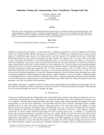
6the number of turns on the primary side by the number of turns of the secondary, shown inEquation 1. Once the turns ratio is found, the voltage Vp on the primary side can be related tovoltage Vs of the secondary side by Equation 2. The current Ip of the primary side can also berelated to the current Is with the turns ratio, shown in Equation 3.a NpNs(1)VpVs(2)1 Ip a Is(3)a In a real transformer, several imperfections must be taken into consideration to create anaccurate model. The major types of imperfections considered are as follows: Copper Losses. Eddy Current Losses. Hysteresis Losses. Leakage Flux.These losses are accounted for with the use of an equivalent circuit of a transformer, asseen in Figure 1. To model the copper losses, resistive components are added to the primary andsecondary windings of the transformer core. These are shown by resistors labeled Rp and Rs. Tomodel the leakage flux losses of the transformer, primary and secondary inductors are added.The inductors are shown with impedance values of Xp and Xs for the primary and secondaryinductors, respectively. The eddy current losses and the hysteresis losses make up the elementsfound in the excitation branch of the equivalent circuit. The core current losses are represented
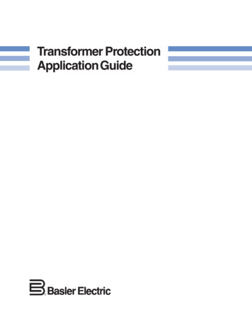
7with resistor Rc and the core excitation effects are represented with an inductor with animpedance of Xm.Figure 1: Equivalent Model of TransformerFor this project, a faultable transformer module is used, seen in Figure 2. This modulewill allow for research to be done on the effects of an internal fault on a transformer through theflipping of a switch.Figure 2: Faultable Transformer Module
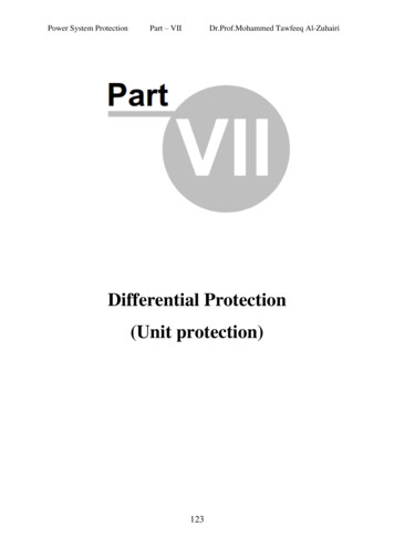
8For this module, the transformer parameters for the equivalent model of a transformerwere found by using the open-circuit and short-circuit tests. By doing these tests, a reasonablemodel of the faultable transformer was found to do testing on.In order to find the parameters of the equivalent model, two methods are used. The firstmethod is the open-circuit test, as seen in Figure 3. This involves leaving the secondary windingof the transformer in an open-circuit, or infinite resistance, while the primary winding isconnected to a full-rated voltage. The open-circuit test is used to find the parameters of the coremodeling the losses of the core. The following equations are used to determine the coreresistance and reactance.Equation 4 is used to find the no load power factor of the transformer, due to the corelosses. The angle (ө) is solved for and used in degrees.𝑐𝑜𝑠(ө) 𝑃𝑜𝑐𝑉𝑜𝑐 𝐼𝑜𝑐(4)Equation 5 is used to find the current through the resistive element (Iw) in the core. Thisvalue is then used in Equation 6 to solve for the core resistance (Rc).𝐼𝑤 𝐼𝑜𝑐 cos(ө)𝑅𝑐 𝑉𝑜𝑐𝐼𝑤(5)(6)Equation 7 is used to find the current through the reactive element (Iu) in the core. Thisvalue is then used in Equation 8 to solve for the core reactance (Xm).𝐼𝑢 𝐼𝑜𝑐 𝑠𝑖𝑛(ө)𝑋𝑚 𝑉𝑜𝑐𝐼𝑢(7)(8)
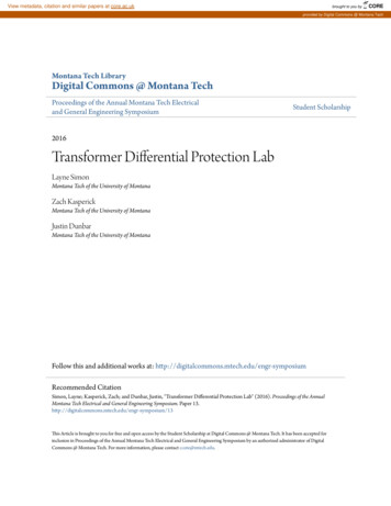
9Figure 3: Open-Circuit TestThe second method is the short-circuit test, as seen in Figure 4. This involves connectingthe secondary side of the transformer short-circuited, or zero resistance, while the primary side isconnected to a variable voltage supply. The voltage is slowly adjusted until the current is equalto the rated value of the transformer. Because the impedance of the excitation branch is muchlarger then series components, a very small amount of current is flowing through the excitationbranch of the transformer and can be ignored. To find the values of Rp and Rs, an ohm meter isused to measure the resistance of the primary and secondary windings while the power supply isturned off. After finding these values, Equation 9 and Equation 10 are used to find Xp and Xs onthe primary side of the transformer. Both these methods will be used to determine theparameters of the faultable transformer.Figure 4: Short-Circuit Test
10𝑋𝑝 𝑉𝑝 𝑅𝑝 𝑅𝑠𝑎2𝐼𝑝𝑋𝑠 3.2.(9)2𝑋𝑝𝑎2(10)Transformer Differential Protection Scheme(Edmund O. Schweitzer, 2010), (Labratories)Transformer differential is a protection scheme that can detect faults that occur internallyin a transformer. Current differential protection, shown in Figure 5, works based on the principlestated by Kirchhoff’s Current Law (KCL) that the sum of the currents flowing into a node isequal to zero. If the per-unit current on the primary side of the transformer is equal to the perunit current on the secondary side of the transformer, then KCL is verified. If KCL is satisfied,no fault is present and the relay will not operate.Figure 5: Transformer Differential Protection SchemeFigure 5 shows a SEL-787 relay connected to the primary and secondary sides of atransformer. The relay is comparing the per-unit current of the primary side (I1) to per-unitcurrent of the secondary side (I2). In this scheme, it is standard to have the CT polarity facing
11away from the differential zone. This results in the two currents, I1 and I2, being 180 out ofphase with each other.The SEL-787 uses two calculated current values to determine if a fault is present, operatecurrent (Iop) and restraint current (Irt). To calculate Iop and Irt, Equation 11 and Equation 12 areused.𝐼𝑂𝑝 𝐼1 𝐼2 (11)𝐼𝑅𝑡 𝐼1 𝐼2 (12)Through several relay settings, further discussed in section 3.1.1.4, the percent dual-slopeoperating curve, shown in Figure 6, is used to set the operate and restraint region for the relay.The operate region is the area above the curve where the relay will trip, ideally only when a faultis present. While the restraint region is the area below the curve where the relay should restrainfrom tripping. Using Iop and Irt values the relay can make tripping decisions based off the percentdual-slope operating curve.Figure 6: Percent Dual-Slope Operating Characteristic
12The following three examples demonstrate how the percent dual-slope operating curveworks in regard to Iop and Irt. Example 1 shows Iop and Irt values which plot in the restrainingregion signifying no fault is present and the per-unit current on the primary side equals the perunit current on the secondary side. Example 2 shows Iop and Irt values which plot in the operatingregion, indicating an internal fault to the transformer where the per-unit current on the primaryside no longer equals the per-unit current on secondary side. Example 3 shows how the second(dual) slope is used to account for CT saturation. When a fault is external to the differentialprotection zone, the relay should not operate. External faults can draw a large amount of current,and if CT’s are not built to withstand the large amount of current present then it will begin tosaturate. If CT values are not equal, it looks like there is differential current present whichresults in the relay operation.Example 1:I1 1.0 0 per-unitI2 1.0 180 per-unitIop 1.0 0 1.0 180 0Irt 1.0 0 1.0 180 2
13Figure 7: Example of Normal OperationA MATLAB representation of the percent dual-slope operating curve can be seenin Figure 7. The restraint current is on the x-axis and the operate current is on the y-axis.The restraining current was calculated to be 2, so this plots 2 in the x-axis. The operatecurrent is calculated to be 0, and this plots 0 in the y-axis. The red dot represents thevalue of (2,0), which are the operate and restraint currents found. The red dot plots in therestraining region and the relay will not operate for this case as expected.Example 2:I1 1.0 0 per-unitI2 1.0 0 per-unitIop 1.0 0 1.0 0 2Irt 1.0 0 1.0 180 2
14Figure 8: Internal Faulted ConditionA MATLAB representation of the percent dual-slope operating curve for Example2 is show in Figure 8. The restraint current is on the x-axis and the operate current is onthe y-axis. The restraining current was calculated to be 2, so this plots 2 in the x-axis.The operate current was calculated to be 2, and this plots 2 in the y-axis. The red dotrepresents the value of (2, 2) which are the operate and restraint currents found. The reddot plots in the operating region and the relay will operate for this case as expected for aninternal fault.Example 3:I1 3.0 0 per unitI2 2.2 180 per unitIop 3.0 0 2.2 180 0.8Irt 3.0 0 2.2 180 5.2
15Figure 9: Example of CT Saturation OperationA MATLAB representation of the percent dual-slope operating curve can be seenin Figure 9. The restraint current is on the x-axis and the operate current is on the y-axis.The restraining current was calculated to be 5.2, this plots 5.2 in the x-axis. The operatecurrent is calculated to be 0.8, and this plots 0.8 in the y-axis. The red dot represents thevalue of (5.2, 0.8), which are the operate and restraint currents found. The red dot plotsin the restraining region and the relay’s differential protection scheme will not operate forthis case of CT saturation because the fault is external to the system. Example 3 simplyshows how the percent dual-slope operating curve accounts for cases of CTsat
The purpose of the Transformer Differential Protection Lab senior design project is to implement the transformer differential protection scheme to protect a transformer when an internal fault is applied. Using the Lab-Volt power suppl