Transcription
Industrial and CommercialMeasurementOhio Gas AssociationTechnical SeminarMarch 2014Ron WalkerDresser Meters & Instruments
OverviewApplication Guidelines SizingInstallation Recommendations Meter set design Mounting & start-upMaintenance Techniques Inspection Testing
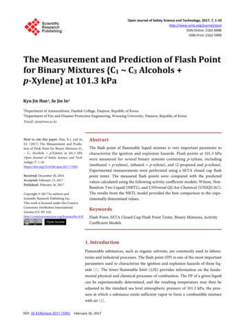
Rotary Meter Operating Principle Gas enters meter, turning the impellers, and fills the cylinder. Bottom & top impellers trap fixed volumes of gas. With each full turn of the impeller shafts, four measuredvolumes of gas are swept through the meter to the right. As impeller RPM increases, gas slippage rapidly decreases
Application GuidelinesProductionTransmissionDistribution
PressureRotary Meter Applications1M - 11M300 psig740 psig1480 psig5C - 5M15-175 psig7M - 102M125-175psigVolume
Sizing Rotary MetersMinimum parameters: Minimum operating pressure Total connected loadApply diversity factors when permissible and/orrequired
Sizing ExampleFor 4,400 scfh (4.4 million BTU/hr.) loadat 25 psig, select meter:a. 5M175b. 3M175c. 2M175d. 15C175e. 8C175
Sizing ExampleFor 4,400 scfh (4.4 million BTU/hr) load at25 psig, select meter using chart 5M175 Oversize3M175 Oversize2M17515C175 10% Over-speed OK*8C175 Undersize
Selection CriteriaGas QualityLine PressureLine TemperatureFlow Rate
Gas QualityMeter SelectionClean & dryStandard version meterWet or sour gasStainless SteelcomponentsFrozen condensationCatalytic HeaterHeavy solidsFluid shut-off device
Line PressureMaximum meteroperating pressureFactor in meterpressure ratingMinimum meteroperating pressureFactor in maximumflow rate (capacity)Pressure controlImpact meter accuracy
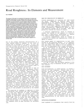
Typical Accuracy Curve
Rotary Accuracy Characteristics At the start rate, meter accuracy istypically at 80 to 90% As flow increases, the accuracy curvequickly flattens out at a nominal100.35% Displacement accuracy is permanent,it never changes
Line TemperatureActual flow increases 1% foreach 5 F. increaseTemperature compensatedindexesMeter temperature operatingrange-40 to 140 F.TC operating range-20 to 100 F.
Flow RateOver-speed protection Restricting flow orificeplate– Request Dresser FormRM-52Splash Lubrication 10% of flow once everyfew weeks
Sizing SummaryIdentify minimum operating pressure andmaximum flow rateConsider selecting smallest possible meter foryour loadInclude adequate equipment in your meter setdesign
Installation SuggestionsBasic meter set design ideasMounting the meter in your setStarting-up your rotary meter
Meter Set DesignAdequate support pipingfor meter flangesEnsure meter is levelInclude hard bypassWhen possible design topinlet flow
Meter Set DesignInstall strainer or filterwhen conditions meritAvoid placing meter atthe low point of a meterset
Meter Set Designsupport piping Flange Spacing Flanges Parallel Pipe Alignment Pipe Level22
Meter Set DesignFlowFlowSide InletTop Inlet(Preferred)23
Meter Set DesignLevel within 1/16”/ft.24
Mounting In Your SetBlow down the metersetUtilize proper flangegasketsFollow manufacturer’storquerecommendations
Start-up preparationOil Fill Plugs (2)RemoteAccess Plug(on Right-EndCover)Rotate ImpellerShaftclockwiseusingScrewdriver orAllen Wrenchto check forfree rotationOil Sight Glasses (2)Carefully Fill to Center
Start-UpClose all valves, taps, & ventsOpen riser & inlet valves and checkfor lveSlowly open outlet valveBypass Valves(2)Close bypass valvesVentRiser ValveDon’t pressurize more than 5 psigper second
Maintenance
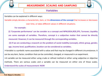
Routine MaintenanceRemoveBowl& CleanScreenas NeededDrain ExcessLiquidsas NeededCheck OilLevel &ColorDrain &Replaceas Needed Using
Oil sight gauge showing proper leveland condition of oil
Routine Maintenance Meter registrationOil color & levelOil leaksCondensation in indexAbnormal meter noiseMeter set levelStrainer sumpGas leaks
Rotary Meter TestingDifferential testingTransfer prover testingIn-service performance testing
Differential TestingLow Equipment CostQuick & EasyReliableAn Inferential Test (i.e. SpinTesting for Turbines)Recognized by NIST since 1948Recognized by AGA (ANSIB109.3)Used by Gas Companies acrossthe U.S.
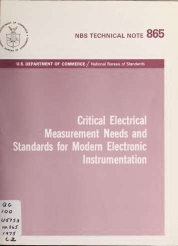
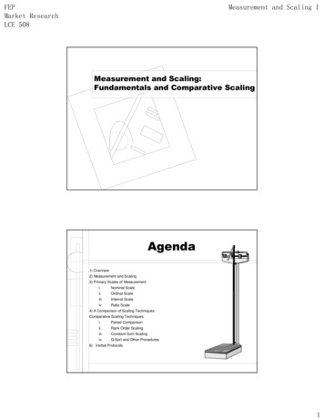
Differential PressureANSI B109.3: “pressureloss across a rotarymeter at specified indexrate, specific gravity, &pressure is indicative ofthe meter’s condition.”
Differential Pressure Varies With:Flow ratePressureSpecific gravityInternal friction
Differential PressureDifferential Pressure(in wc)5M B3 Differential Pressure at Meter Tapsin 0.6 S.G. Natural Gas151050050100150Percent of Rated Capacity in 0.6 S.G. Natrual Gas (%)8" wc15 psig45 psig90 psig125 psig175 psig
Differential TestingLook for 50% increaseTry flushing meter with approvedsolvent to restore meter conditionand accuracy
Transfer Proving Higher equipment costthan DifferentialTestingLimited to 10 MACFHNot for HazardousLocationsReliableA Volumetric ratherthan an Inferential Testproviding directAccuracy resultsCompares volume ofMaster Meter to FieldMeterMeasures andcompensates for inletpressures andtemperaturesTertiary Standardtraceable to NIST
Rotary Meter AdvantagesCompact installations.Accurate operational range.Maintains accuracy after severalyears of service.Mechanical design provides longservice life.Low cost maintenance.Large number of installationsthroughout the world.
What’s New?40
Self DiagnosticsIMC-DPX41
Electronic TC Meter42
Dresser ETC43
D800 and D1000Commercial Service Meter44
AMR DevicesSeries B3 meter with Itron Residential AMRERT can be mounted on either LMMA or S3AAccessory Units45
Thank you.
Recognized by AGA (ANSI B109.3) Used by Gas Companies across the U.S. Differential Pressure ANSI B109.3: “pressure loss across a rotary meter at specified index rate, specific gravity, & pressure is indicative of the meter’s condition.” Differential Pressure Varies With: Flow rate Pressure Specific gravity Internal friction. Differential Pressure 5M B3 Differential Pressure at Meter Taps .