Transcription
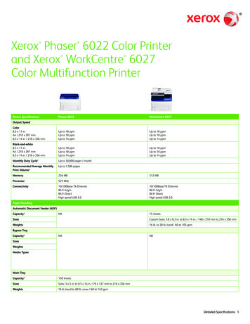
Ender-3 3D PrinterInstructions for assembly This guide is for the Ender-3 3D printer. Select the correct input voltage to matchyour local mains (220V or 110V). Because of software/hardware upgradesand model differences, new revisionsmay not be listed in this guide. Detailed instructions for use areavailable on the SD card.
Step1. BOMa. Remove the parts from the box andremove any tape and padding from theparts. Inspect the parts to make surethey were not damaged in shipment.b. Check the items on List 1 and List 2.The wiring harness of component (Ba)and component (N) has already beenconnected.
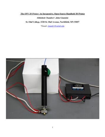
Step 2. Install aluminum extrusions (L) and (R) to base (Ba)Prepare the following parts:a. M5x45 socket head hex screws (4x)b. M5 washer (4x)c. Aluminum profiles (L) (1x)d. Aluminum profiles(R) (1x)e. Base (Ba) (1x)f. 4mm Allen keyStep 1. Place (L) on the left and keep the direction of the base(Ba) facing front;Step 2. Place the aluminum profile (L) vertically over the left sideframe of the base (Ba), be careful that the (L) profile has thethreaded holes with the short sides facing downwards. Usingthe M5x45 screws and washers, pass through bottom hole ofthe aluminum profile at the left side of the base (Ba), align thethreaded hole at the bottom of the aluminum profile (L), andtighten the screw with an hexagon wrench;Step 3. Place the aluminum profile (R) vertically over the rightside frame of the base (Ba). Note that the (L) profile has throughholes with the short sides facing downwards. Also note that theholes are to the left (see diagram) to ensure that the aluminumprofiles are oriented correctly. , Using M5x45 screws andwashers, pass them through bottom hole of the aluminumprofile at the right side of the base (Ba), align the threaded holeat the bottom of the aluminum profile (R), and tighten with the4mm Allen key.
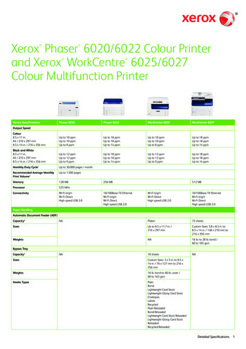
Step 3. Power supply and operation screen installationPrepare the following parts:a. M5x8 hex drive rounded head screws (2x)b. Operation screen assembly(S) (1x)c. M4x20 socket head hex screws (2x)d. Switching power supply assembly(P)(1x)e. 3mm Allen keyf. *Select the correct input voltage tomatch your local mains (220V or 110V).Step 1. Keep the the base (Ba) facing towards you.Step 2. Align the hole at the bottom left of the operation screen with thethreaded hole of the aluminum profile on the right side of the base (Ba),secure with M5x8 screws, and use the Allen key to tighten them.Step 3. Attach the switching power supply unit to the bottom as show on thediagram to the left (button switch at the bottom right). Screw holes of theswitching power supply should pass through the holes of the aluminumprofile (R). Using M4x20 screws, pass through the front of the profile (R) anduse the Allen key to tighten the screws.
Step 4. Z axis limit switch installation1. Prepare limit switch assembly (ZI) and 3mmAllen key;2. The direction of the base (Ba) stays at thefront, and the switch assembly (ZI) is mountedon the left side of the base (Ba) (as shown inthe diagram on the);3. Loosen the T-nut by hand until it is at theend of the threads, but not so far it might falloff. Then, fit into the slot in the aluminumprofile. When the bolt is tightened, the nutrotates 90 degrees and then grasps the insideof the slot.4. Align the T-nut with the bottom aluminumprofile groove and secure with the Allen key5. The limit switch assembly (ZI) has a smallhook that attaches to the aluminum profileunderneath the base (Ba) (reference: about 32mm from the bottom).
Step 5. Z axis motor assembly installationPrepare the following parts:a. T8 Acme lead screw (1x)b. M4x18 hex drive flat headscrews (2x)c. Z-axis motor assembly (Zm)(1x)d. 2.5mm Allen keyStep 1. Rotate base (Ba) 180 until the back is facingtowards you.Step 2. Position the hole of Z-axis motor assembly atthe threaded hole of the aluminum profile (L) in thebase (Ba), secure with M4*18 screws, and tighten thescrews with a 2.5mm Hexagon wrench.Loosenthe screwStep 3. Use a 2.5mm Hexagon wrench to loosen thescrews of the Z-axis coupling to prepare for insertionof the lead screw.Step 4. Insert the T8 lead screw into the coupling, andtighten the screw that was loosened in the previous
Step 6. X-axis bearing installation preparationPrepare the following parts:a. Aluminum profiles(B1)-(1x)b.M4x16 Hex drive rounded head screws (4x)c. M4 Washer (4x)d. Extrusion assembly (E) (1x)e. Nozzle kit (N)-(1x). The wiring harness ofcomponent (N) and component (Ba) hasalready been connected.f. Timing belt(Be)-(1x)g. Pulley assembly(K2)-(1x)h. Belt tensioner(K1)-(1x)i. 2.5mm Allen key
Step 7. X-axis assembly (part 1)Step 1. Assembly of aluminum profile (B1) and extrusionassembly (E). Aluminum profile (B1) is shown in the diagramon the left(1). Pay attention to the position and direction ofthe large hole. Align the hole of extrusion assembly (E) withthe threaded hole of aluminum profile (B1), it should benoted that the hole has two plates, which aresecured withM4*16 screws, and fixed to the second profile plate and thealuminum profile (B1). Use a suitable Allen key to tighten thescrews.Step 2. Adjust the direction of the nozzle kit(N) as shown inFigure (3). Hold one end of the timing belt in the slot on theright side underneath the nozzle kit (N), and the other end inthe path shown in Figure (2). Go through the extrusionassembly (E), bypass the synchronizing wheel, and slide thenozzle kit (N) from the left into the aluminum profile whenthe path of figure (2) completes three quarters (in the redline position in Figure 2). Then, complete the path of the beltas shown in Figure (2). Then, stick the other end of the beltto the slot on the left side below the nozzle kit (N).Step 3. Position the pulley assembly (K2) in the positionshown in Figure (3), align the threaded hole in the aluminumprofile on the left side of the profile (B1), pass it with theM4*16 screw, and use the 2.5mm hexagon wrench to lockthe screw;Note. As you complete easy step, be sure to place theparts according to the diagram on the left side.
Step 8. X-axis assembly (Part 2)Step 1. Prepare belt tensioner assembly (K1) and3mm Allen key.Step 2. Rotate the X-axis assembly180 horizontally.Step 3. Pick up the belt tensioner assembly (K1).Loosen the T-nut by hand until it is at the end ofthe threads, but not so far it might fall off. Then, fitinto the slot in the aluminum profile. When thebolt is tightened, the nut rotates 90 degrees andthen grasps the inside of the slot.Step 4. Align the T-nut with the top aluminumprofile groove. Use an Allen key to tighten thescrew. Be careful not to tighten it all the way. Makesure that the external actuator assembly (K1) canbe slid easily.Step 5. Align the belt so that one end fits over thegeared pulley in the extrusion unit (E) and one endfits over the idler in the belt tensioning assembly(K1). Apply tension in the direction of the redarrow to the left and use an Allen key as a lever topush the belt around the pulley. Tighten the beltand then tighten the two screws.Step 6. Check the tension of the belt driving the Xaxis (on the gantry). The belt should be taut, withno slack or slop.
Step 9. X, Z bearing assemblyStep 1. Prepare 2mm and 2.5mm Allen key.Step 2. The direction of the base (Ba) keeps the end in frontand rotates the X-axis assembly horizontally by 180 .Step 3. Align the pulleys on both ends of the X-axis assemblywith the aluminum chute on the base (Ba). Align the screwrod with the nuts in the extrusion assembly (E). Use theappropriate Allen key to slightly loosen the screws thatholding the nuts. Mount the X-axis assembly on the base (Ba)Step 4. Manually apply force and slide the X-axis assembly upand down to slowly lock the screws that secure the nut.Step 4. Slide the X-axis assembly up and down again to makesure the slide is smooth. If it is not smooth, try loosening thescrews of the coupling slightly, turning the screws gently, andslowly tightening the screws.
Step 10. Fix the gantry framePrepare the following parts:a. M5x25 socket head hex screws (4x)b. M5 Washer (4x)c. Profile end caps(C)-(2x)d. Aluminum profiles (B2)-(1x)e. 4mm hexagon wrenchStep 1. Take out the aluminum profile(B2), pay attention to the counterborehole at the top (see the figure on the left),align the aluminum profile (B2) hole withthe threaded hole of the base (Ba), usethe M5*25 screw and washer, from thetop go through the aluminum profilehole(B2), use a 4mm Allen key to tightenthe screws.BackStep 2. Take out the end cover (C) of theprofile, and attach it to the ends of thealuminum profile (B2). Apply a littlepressure and insert it into it. The end faceof the aluminum profile may be sharp. Becareful not to scratch your hand.
Step 11. Rack installationPrepare the following parts:a. Plastic tube(R1)-(1x)b. Plastic nut (2x)c. Sheet metal bracket(R2)-(2x)d. M5x8 Hex Drive Rounded Head12Screws (2x)e. M5 T-nuts (2x)f. 4mm Allen KeyStep 1. Install one end of the plastic tube (R1)on the sheet metal bracket (R2), hand-tightenthe plastic nut on the end of the plastic tube(R1) and tighten by hand.Step 2. Use a M5x8 screw to pass through thehole of the sheet metal bracket (R2). Handunscrew the M5 T-nut until it it is on the lastfew threads of the screew.Step 3. Align the T-nut with the top aluminumprofile groove and tighten with an Allen key.Step 4. The Ender-3 mechanical part installationhas been completed.
Step 12. Tube and wire connectionStep 1. Rotate the printer by 90º5126Step 2. Find the letters on the1/2/4/7/8 wire harnesses, as shownon the left, and insert it according tothe position indicated by the redarrow on the drawing. After theinsertion, gently pull on it to insureit’s firmly seated. Note that the X/Zwide plug corresponds to the motor,and the narrow plug corresponds tothe limit switchStep 3. Red and black heated bedconnector (3#) connector can bedirectly inserted.3748Step 4. Connect the white PTFEBowden tube from the hot end to theyellow tube upper coupler extruder(See 5#). Insert the tube firmly intothe joint extruder and feel it slide inand lock the position.Step 5. The plug on the 6# harness isinserted into the display board intothe jack marked "Exp3.LeftStep 6. Check that all harnesses aresecurely connected.
Shenzhen Creality3D Technology CO.,LTD.O f f i c i a l We b s i t e : www.creality3d.cnCompany Address: 12F, Building No.3, Jinchengyuan IndustrialArea, Huafan Road,Dalang, Longhua, Shenzhen, Guangdong Province
Ender-3 3D Printer Instructions for assembly . a. Remove the parts from the box and remove any tape and padding from the parts. Inspect the parts to make sure they were not damaged in shipment. b. Check the items on List 1 and List 2. The wiring har