Transcription
EVOLUTION 1INK JET PRINTERSINSTALLATION AND OPERATION MANUALdigital design inc.67 Sand Park RoadCedar Grove, NJ 07009(973) 857-9500http://www.evolutioninkjet.com/This manual is for use in operating and maintaining the EVOLUTION 1 Ink JetPrinter. This includes various optional features, which may not be included inyour basic model printer. For basic start-up instructions, please refer to PART 1Installation Procedures.All rights reserved. No part of this document may be reproduced, stored on aretrieval system, or transmitted in any form, or by any means electronic,mechanical, photocopying, recording or otherwise, without the prior permission ofDigital Design Inc.Digital Design Inc. has a policy of continual product improvement. The Companytherefore reserves the right to modify the information contained in this manualwithout prior notice.ALL PRINT CARTRIDGES SUPPLIED BY DIGITAL DESIGN INC.ARE FACTORY TESTED AND PROFILED TO PRODUCE ANOPTIMUM AND CONSISTANT CODE. USING OTHER THANAUTHORIZED CARTRIDGES WILL CAUSE UNDESIRABLERESULTS.EACH FLASH DATA CARD IS PROFILED EXPLICITELY FOR ITS’INTENDED PRINTER, AND IS SECURITY LOCKED PROHIBITINGUSE IN OTHER THAN THE ORIGINAL PRINTER FOR WHICH ITWAS PURCHASED. KEEP ALL UPGRADE CARDS IN A SECUREPLACE.EVOLUTION 1 IS A BASIC MODEL WITH NO VARIABLE FIELDPROGRAMMING CAPABILITIES. OPTIONAL SOFTWARE MAYBE ADDED TO A BASIC UNIT AND IS COVERED IN THISMANUAL.1EVOLUTION 1 SYSTEM MANUAL Issue 1.5 26 Sept 2006
INSTALLATION AND OPERATION MANUAL . 4PART 1: INSTALLATION PROCEDURES. 4INSTALLING THE EVOLUTION 1 PRINTING SYSTEM. 4MOUNTING ON PRODUCTION LINE . 4EVOLUTION II MOUNTING OPTIONS. 5GROUNDING STRAP INSTALLATION . 7INPUT POWER CONNECTION AND MODIFICATION. 7INSTALLING THE PRINT CARTRIDGE. 8CONNECTING THE CONTROLLER TO THE CARRIAGE. 9CONFIGURING THE PRINTER . 10SYSTEM RESET . 10MULTIPLE PRINT HEADS . 11EVOLUTION 1 QUICK START . 12CHANGING LANGUAGE PROMPTS . 12ENABLING PRINT MODE. 12HEAD SELECT MODE. 12ENTERING A MESSAGE. 13STORING A MESSAGE (OPTION PACK 1, 1.5, 2 or 3) . 14LOADING A MESSAGE ((OPTION PACK 1, 1.5, 2 or 3) . 15EVOLUTION 1 QUICK SETUP . 16PART 2: OPERATION PROCEDURES. 1OVERVIEW. 1CONTROLLER AND LCD . 1KEYPAD KEY DESCRIPTIONS. 2TURNING ON THE PRINT STATION FOR THE FIRST TIME. 3CHECKING SYSTEM INFORMATION . 3CHECKING LOADED FONTS . 3CHANGING SYSTEM DATE AND DAY OF WEEK CODES (OPTION PACK 2 INSTALLED)4CHANGING SYSTEM TIME AND DATE ROLL OVER TIME. 5PROGRAMMING . 7DEFINITIONS. 7PRINT MODE AND STOPPED “COMMAND” MODE. 7F1 MENU. 8F1 MENU. 91 CHARACTER SPACING: . 92 EXT. ENCODER:. 93 DATE OFFSET: (OPTION PACK 3 ONLY). 10F2 MENU. 111 - DIRECTION:. 112 - PRINT INVERSE: . 113 – PRODUCT DETECT:. 114 - AUTO REPEAT: (OPTION PACK 1, 2 OR 3). 12F3 MENU. 131 – PRODUCT COUNT: (OPTION PACK 3 INSTALLED) . 132 – shift code: (OPTION PACK 3 INSTALLED). 143 – DATE FORMAT: . 154 – TIME FORMAT: . 17F4 MENU. 181 - LANGUAGE:. 182 - INK SUPPLY: . 183 – SET UNIT I.D.:. 194 – LOAD CARD:. 20SETTING PRINT DELAY AND LINE SPEED. 23SETTING LINE SPEED. 232EVOLUTION 1 SYSTEM MANUAL Issue 1.5 26 Sept 2006
SETTING PRINT DELAY . 24INPUT, EDIT OR DELETE MESSAGES . 25MESSAGE STORAGE (OPTION PACK 1, 1.5 OR 2) . 34STORING A MESSAGE. 34RECALLING A STORED MESSAGE. 34PART 3: MAINTENANCE PROCEDURES. 1PERIODS OF SHUT DOWN. 1SHORT PERIODS OF SHUT DOWN . 1LONG PERIODS OF SHUT-DOWN . 2PRINT CARTRIDGE MAINTENANCE. 3PRINT CARRIAGE MAINTENANCE . 5EXPLODED VIEW OF THE C21002 PRINT CARRIAGE. 5PART 4: TROUBLESHOOTING AND REPAIRS . 1FAULTS . 1PART 5: PARTS LIST AND OPTIONS. 1PART 6: COMMUNICATIONS PROTOCOL . 1DESCRIPTION. 2DATA WORD DEFINITION . 2BAUD RATE . 2DEFINITIONS. 2CABLING FOR EVLINK ENVIRONMENT . 2HARDWARE INTERFACE . 3PHYSICAL CONNECTIONS RS485 print carriage. 3PROTOCOL FORMAT: . 3EVOLUTION PRINTABLE CHARACTER SET . 3SOFTWARE PROTOCOL . 4ERROR CODES . 4COMMANDS:. 6PART 7: OPTION JUMPERS AND CABLING . 1OPTION JUMPER DESCRIPTIONS . 1VSEL J7. 1ENSEL J9 . 1PRSEL J10 . 1JUMPER LOCATION . 2OPTION CABLING DESCRIPTIONS . 3PART 8: SPECIFICATIONS . 1PRINTER SPECIFICATIONS . 1PRINT CHARACTERISTICS. 1CONTROLLER . 1PRINT CARRIAGE. 1ENVIRONMENTAL CONDITIONS. 1GENERAL . 1DEFAULT SETTINGS. 23EVOLUTION 1 SYSTEM MANUAL Issue 1.5 26 Sept 2006
INSTALLATION AND OPERATION MANUALPART 1: INSTALLATION PROCEDURESINSTALLING THE EVOLUTION 1 PRINTING SYSTEMCaution should be taken while installing the EVOLUTION 1 printing system on yourequipment. Digital Design Inc. has taken every precaution to ensure a safe andaccurate instruction set to guide the installer through the installation process.Follow the operational guidelines in the installation procedures.VERIFY THAT YOUR EQUIPMENT IS IN PROPER OPERATINGCONDITION.LOCATE A CONVENIENT POSITION ON YOUR EQUIPMENT.EVOLUTION 1 REQUIRES 4-1/2" OF SPACE ON THE PRODUCTIONLINE.FOLLOW THE INSTALLATION PROCEDURES.READ CAREFULLY ALL INSTALLATION PROCEDURES BEFOREPROCEEDING.INSTALL THE PRINTING SYSTEM ON YOUR EQUIPMENT.THERE IS NO EXTRA HARDWARE REQUIRED OTHER THENTHAT SUPPLIED IN THE INSTALLATION KIT.MOUNTING ON PRODUCTION LINELocate the supplied mounting templateand affix in a convenient location on theproduction line. Spot and drill bothmounting holes for a 5/16” bolt. NOTE:the user may also thread the side of theconveyer using a 5/16” tap.Fasten the mounting bracket to theconveyer using the supplied mountinghardware and ensuring that the suppliedground strap is located securely beneatheither of the two mounting bolts, and thatconductivity to earth ground is less than 1 ohm. This ensures a proper path forstatic discharge, should the need arise.4EVOLUTION 1 SYSTEM MANUAL Issue 1.5 26 Sept 2006
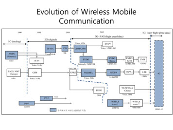
EVOLUTION II MOUNTING OPTIONSThe EVOLUTION II mounting bracket assembly C21010 has a number ofpossible mounting configurations, which allows adaptability to a variety ofproduction equipment.The top cross slidebracket C20741 may berotated 180 deg byloosening the includedsetscrew 504JCS androtating the bracket. Thisallows the print head to beextended by just over 1”.Although this is not asignificant amount it mightbe helpful.Refer to the first twopictorials to identify thevarious components of themounting bracket systemC21005.Rotating the horizontalmounting bracket line.Themounting centers for boththe base block C20741andcontrollerholderC20940-4 are identical.Remove the two 502JHSflat head screws from thebase block and the two502JESbuttonheadscrews, rotate the bracketand replace both the baseblockandcontrollerholder.The above procedureallows for a print headdisplacement from .625”before the production lineto11.450”intotheproduction line.5EVOLUTION 1 SYSTEM MANUAL Issue 1.5 26 Sept 2006
Vertical height adjustmentfor the EVOLUTION II printhead is accomplished byloosening the includedhand knob 5993K41.Note that the hand knobmay be mounted on eitherside of the horizontalmountingbracketdependingontheorientation of the bracket.It should also be notedwhen rotating the crossslide assembly it isnecessary to move thesmallerhandknob57715K16 to the otherside of the bracket so italigns with the flat on thehorizontal extension rod.After the mounting bracketis configured loosen thelocking collar 7A014S andre-locate it against thehorizontalextensionbracket and tighten. Thisallows the user to loosenthe horizontal mountingbracket-locking knob androtatetheassemblywithout losing the heightadjustment.6EVOLUTION 1 SYSTEM MANUAL Issue 1.5 26 Sept 2006
GROUNDING STRAP INSTALLATIONINSTALL STRAPUNDER 5/16”SCREW. ENSURECONDUCTIVITY TOEARTH GROUND ISLESS THAN 1 OHMINPUT POWER CONNECTION AND MODIFICATIONInsert the power plug to the available power source. The supplied power supplywill is universal and will auto detect 100/240 VAC 50-60hZ.No other adjustments are necessary.7EVOLUTION 1 SYSTEM MANUAL Issue 1.5 26 Sept 2006
INSTALLING THE PRINT CARTRIDGERemove the protective film from the face of the print head and retain the film.This protective film may be re-applied to store partially used cartridges. If it isnecessary to remove the print head and store for a long period of time, it is bestto re-apply the plastic film, and place the cartridge in a closeable plastic bag.Rotate the Print Head Release mechanism to the rear of the print head so that itis free for insertion of the print cartridge. Push the print cartridge in and down toinsert it into the print carriage. Gently lift the locking arm and press forwardagainst the print cartridge. A snap will be felt as the locking mechanism pressesthe cartridge into the correct position.NOTE: EACH PRINT CARTRIDGE HAS BEEN PROFILEDAT THE FACTORY. THIS PROCEDURE DETERMINESTHE OPTIMAL OPERATING CHARACTERISTECS FOREACH INDIVIDUAL CARTRIDGE. USING ANY OTHERPRINT CARTRIDGE WILL HAVE UNDESIRABLERESULTS.NOTE: WHEN A NEW CARTRIDGE IS INSTALLED,BOTH THE RED AND GREEN LIGHT WILL FLASHTWICE INDICATING A CORRECT INSTALLATION.THE USER MUST REMEMBER TO RESET THE INKLEVEL UNDER THE F4 FUNCTION KEY.8EVOLUTION 1 SYSTEM MANUAL Issue 1.5 26 Sept 2006
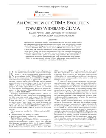
CONNECTING THE CONTROLLER TO THE CARRIAGEConnect the Controller to the print carriage using the supplied 3 FT (.9 mm)interconnect cable C21008-3 supplied with the Printing System. The cable is astandard RJ50 (10 conductor). Longer cables are available as required.Connect either end of the cable to the Carriage Assembly and securely lock inplace. NOTE: THE CONNECTOR MUST BE PLUGGED INTO THE INPUT RJ50CONNECTOR LOCATED ADJACENT TO THE LED’S AND MARKED WITHAN ARROW POINTING TO THE CONNECTOR. A click will be heard when theconnector is in the appropriate position. Connect the free end to the ControllerAssembly and ensure connector is securely seated.RESETSWITCHACCESSHOLEPRINT CARRIAGE RJ50OUTPUT CONNECTORPRINT CARRIAGE RJ50INPUT CONNECTORGREENCYCLE LEDRED PRINTENABLE LEDPOWER INPUT 12VDC @1.5ACONTROLLER RJ50CONNECTORCAUTION:NOTE ORIENTATION OF THE CONNECTORS. DO NOT FORCECONNECTORS INTO POSITION SECURELY LATCH (CLICK) INTOPOSITION.CONTROLLER MUST PLUG INTO THE PRINT CARRIAGE RJ50 INPUTCONNECTOR FOR PROPER OPERATION. THE PRINT CARRIAGE RJ50OUTPUT CONNECTOR IS USED EITHER FOR CONNECTION TO THE NEXTPRINTER ON A NETWORK OR FOR EXTERNAL PRODUCT OR EXTERNALENCODER INPUT.THE POWER INPUT CONNECTOR MUST BE SECURELY INSERTED INTOTHE PRINT CARRIAGE. UPON PROPER INSERTION BOTH THE RED ANDGREEN LED’S WILL FLASH INDICATING PROPER CONNECTION.9EVOLUTION 1 SYSTEM MANUAL Issue 1.5 26 Sept 2006
CONFIGURING THE PRINTERTo verify the current operating software press the STOP PRINTkey.Press the V keyCONTROLLER 7.08PRINTER 2.08JPRINTER SN XXXXXXEXIT ANY KEYThe first line indicates the version of the controller softwareThe second line numeric indicate printer software version and the letter is thefirmware version of the printer. The ‘ ’ (s) following indicate options installed: Option 1 Option 1.5 Option 1 and Option 1.5 Option 2 Option 3The third line indicates the serial number of the printerSYSTEM RESETThere are two types of resets available in the Evolution printing system. The firsttype of reset is a SOFT RESET.ERASE STOREDMESSAGESYES OR NO Y/NPressing the R key while applying power to theunit will display the reset command modeCAUTION: A response of Y will delete all storedm
10 EVOLUTION 1 SYSTEM MANUAL Issue 1.5 26 Sept 2006 CONFIGURING THE PRINTER To verify the current operating software press the STOP PRINT key. Press the V key The first line indicates the version of the controller software The second line numeric indicate printer software version and the letter is the firmware version of the printer.