Transcription
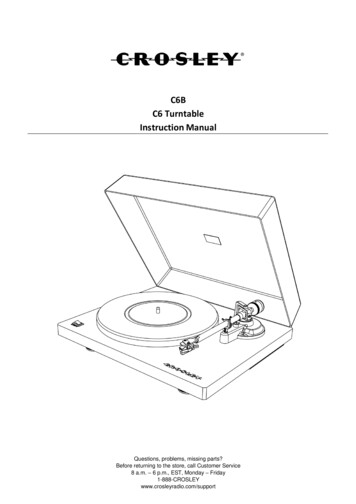
The OPN 3D Printer: An Inexpensive, Open-Source Handheld 3D PrinterAbhishek Chandra*, John GianniniSt. Olaf College, 1520 St. Olaf Avenue, Northfield, MN 55057*Email: chandr1@stolaf.edu1
Table of ContentsIntroduction .3Constructing the OPN 3D Printer .4Constructing and Configuring the OPN 3D Printer Temperature Control Box .4Constructing and Configuring the OPN 3D Printer Handle and Gear Mechanism .17Using the OPN 3D Printer .24Hazards .29Acknowledgements and Disclosures .29References .302
IntroductionIn the past twenty years 3D printing technology has rapidly evolved and continues to expand itsutility in additive manufacturing. Today 3D printing has utility in a number of industries fromautomobile repair to medical technology (1-3). With decreasing costs, commercial printers havebecome readily available for the casually interested (2, 4). These printers, while powerful, areprone to errors that can mar prints or render them ineffective. The most common errors in printsare gaps or holes in the solid (3-5). This can result in a loss of detail or function depending on theprint. This has been a challenge in designing many of the prototypes in our own lab (The OPNLab). These mistakes are often caused by errors in the G-code or incomplete object scanningwhen developing an STL file (2, 5). Often, the only fix to such a problem is to repeat a printusing a slower print speed (3). This can be an expensive and time-intensive process. To the bestof our knowledge, there is not an easy method of printing on a previously cooled solid to fix anyerrors.In an effort to avoid or fix these errors, research is being done to refine 3D printing technology.A number of handheld printers are available for sale, such as the LESHP 3D Printing Pen(and similar models from vendors like Sunveza , NEXTECH , and 3Doodler ). However,these devices are relatively expensive with costs ranging from 50.00 to 150.00, not includingshipping or tax. Furthermore, many of these personal handheld printers suffer from limitations ofthe types of useable filament.As a way to bring down the cost of handheld 3D printers and make the process of printcorrection more widely available to all, this manual describes how to 3D print and construct apersonal handheld 3D printer with an estimated cost of 25.00 when using self-printed parts.This manual also describes how to use this handheld 3D printer to fix gaps and errors in prints sothat any user can repair existing prints without reprinting an entire project.Finally, in keeping with the names given to the other instruments and pieces of equipmentdeveloped in the OPN Lab, our handheld 3D printer is called the OPN 3D Printer. This name isused because the device’s plans and parts are intended to be open-source and publically availablefor all to use. We hope that the OPN 3D Printer will be a useful tool in the development andproduction of 3D printed designs.3
Constructing the OPN 3D PrinterThe construction of the OPN 3D Printer uses 3d printed parts and items readily available onlineor in most hardware stores (an extruder head, temperature control board, and 12V power source).For readers without access to 3D printing technology, there are a number of online vendors(Shapeways , makexyz ) that will print and ship any STL files for a fee based on the size andvolume of the part. http://3dprintingpricecheck.com/ estimates a cost of 28.30 to print therequired STL files for the OPN 3D Printer using makexyz 3D printing service (value calculatedin August 2017). In the long term, purchasing a mainline commercial 3D printer ( 500 or less)and the related filament ( 25 or less) will be a more economical option, especially if printingmultiple parts over time.Constructing and Configuring the OPN 3D Printer Temperature Control BoxTo make and configure the OPN 3D Printer Temperature Control Box, readers will need thefollowing materials: Standard 3D printer and related filament (ABS filament was used; PLA will suffice)CAD and STL files for the OPN 3D Printer Temperature DC 12V K-Type Digital Thermostat (LM YN Digital Thermostat K-Type DC 12V RedLight, Temperature Controller Board and Module Switch, X0017QMRP3)1.75mm Filament Extruder Hot End (Haobase Assembled Extruder Part Hot End for 3DPrinter, 1.75mm Filament Direct Feed 12V Extruder with 0.4mm Nozzle, X0015F8HC3)12V, 3.5Amps AC Adapter (TCP Electronics Co. LTD 12V AC Adapter, Model Number:ADBC12350BB)#4 14.7mm length steel slot screws (4X)Tapping screw with M6 x 0.75 tapPower drill with 0.25inch drill bit5.0inch insulated copper wireMetric ruler4
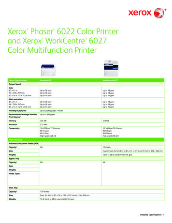
STEP 1: Print the STL files for the OPN 3D Printer temperature control box (Available on The OPNLab website).Using a power drill and a 0.25inch drill-bit, bore a hole 14.55mm deep in the center of bothcolumns found in the back plate.With an M6 x 0.75 size tap, use a tapping screw to cut threads in the bored holes. (Fig. 1)Threaded Columns123Figure 1: The image shows the numbered ports and threaded columns of the back plate.5
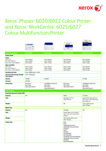
STEP 2: Loosen screw caps 1-6 on the back of the digital thermostat. (Fig. 2A-B)Remove the blue and red ends of the temperature control element from screw caps 1 and 2 ofthe digital thermostat.Run the blue and red ends of the temperature control element in through port number 2 of theback plate.Secure the red end of the temperature control element under screw cap 1 of the digitalthermostat.Secure the blue end of the temperature control element under screw cap 2 of the digitalthermostat.Tighten screw caps 1 and 2 on the back of the digital thermostat. (Fig. 3)Temperature ControlElementAFigure 2A: The image shows the front face of the digital thermostat and the attachedtemperature control element.6
125 63 4BFigure 2B: The image shows the back face of the digital thermostat with numbered screw caps.2 1321Figure 3: The image shows the proper wiring of the temperature control element to the digitalthermostat through the back plate.7
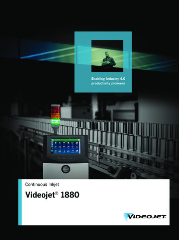
STEP 3: Remove the thermocouple attached to the filament extruder hot end. (Fig. 4A-B)Strip 0.5 inches off of the ends of both red wires of the heating element leading away fromthe filament extruder hot end.Run one of the stripped red wires of the heating element in through port number 1 and theother stripped wire in through port number 3 of the back plate.Secure one of the stripped red wires of the heating element under screw cap 3 and the otherunder screw cap 6 of the digital thermostat. (Fig. 5)ThermocoupleAFigure 4A: This image shows the filament extruder hot end and attached thermocouple.BFigure 4B: This image shows the filament extruder hot end with the thermocouple removed.8
33216Figure 5: This image shows the correct wiring of the filament extruder hot end to the digitalthermostat through the back plate.9
Step 4: Strip 0.5 inches of insulation off of both ends of the 5.0inch insulated copper wire.Run one end of the insulated copper wire in through port number 1 and the other end inthrough port number 3 of the back plate.Secure one end of the insulated copper wire under screw cap 4 and the other end under screwcap 5 of the digital thermostat. (Fig. 6-7)34251Figure 6: This image shows the correct wiring of the copper wire to the digital thermostatthrough the back plate.10
Figure 7: This close-up image shows the correct wiring of the temperature control element,filament extruder hot end, and copper wire to the digital thermostat.Step 5: Strip 1.5 inches off of the output end of the AC adapter cord. Separate the exposed wires intotwo bundles. (Fig. 8)Run both stripped bundles of the AC adapter cord in through port number 3 of the back plateSecure one stripped bundle of the AC adapter cord under screw cap 3 and the other bundleunder screw cap 4.Tighten screw caps 3, 4, 5, and 6 on the back of the digital thermostat. (Fig. 9-10)11
Figure 8: This image shows the AC adapter with output cords stripped and separated into twobundles.33421Figure 9: This image shows the correct wiring of the AC adapter cord to the digital thermostatthrough the back plate.12
Figure 10: This image shows the correct wiring of the temperature control element, filamentextruder hot end, copper wire, and AC adapter cord to the digital thermostat.13
Step 6: Orient the digital thermostat such that the holes in the upper corners of the thermostat alignwith the bored holes in the column and the display is visible.Using two #4 14.7mm steel slot screws, secure the digital thermostat to the back plate. (Fig.11)Figure 11: This image shows the digital thermostat secured to the back plate.14
Step 7: Use a hex driver to loosen the hex screws securing the port of the filament extruder hot endadjacent to the heating element port.Use a 0.25inch drill bit to drill the port adjacent to the heating element port.With an M6 x 0.75 size tap, use a tapping screw to cut threads in port of the filament extruderhot end adjacent to the heating element port. (Fig. 12A)Insert the temperature control element of the digital thermostat into the threaded port of thefilament extruder hot end.Use a hex driver to tighten the hex screws to secure the temperature control element in thethreaded port. (Fig. 12B)APort to bedrilled andthreadedFigure 12A: This image shows the filament extruder hot end with the port to be threaded.BTemperatureControl ElementFigure 12B: This image shows the filament extruder hot end with the attached temperaturecontrol element.15
Step 8: Place the front plate over back plate.Use a power drill and a 0.25inch drill-bit, bore a hole 14.55mm deep in through the side ofthe front plate and into the back plate. (Fig. 13A)o The hole should be placed 13.66mm from both the face and back of the front plateand 1.3mm from the top edge of the front plate.o The hole must be made on both the right and left sides of the temperature controlbox.With an M6 x 0.75 size tap, use a tapping screw to cut threads in the bored holes.Using two #4 14.7mm steel slot screws, secure the front plate to the back plate. (Fig. 13B)AFigure 13A: This image shows the correct location of the bored hole in the front plate.BFigure 13B: This image shows how the steel slot screws secure the front plate to the back plate.16
Constructing the OPN 3D Printer Handle and Gear MechanismTo make and configure the OPN 3D Printer Handle, readers will need the following materials: Standard 3D printer and related filament (ABS filament was used; PLA will suffice)CAD and STL files for the OPN 3D Printer Temperature Traxxas 3955 40-T Spur Gear (0.5 x 3.13 x 4.88inch)Power drill with a 0.25inch drill bit4.0mm steel slot screw, 33mm in length2x2inch square steel sheet (2X)4.4mm steel hex nut (2X)4.0mm steel hex nutEpoxy glueStep 1: Print the STL files for the OPN 3D Printer handle (Available on The OPN Lab website)(Fig. 14)TopBottomFigure 14: This image shows the printed handle piece.17
Step 2: Use a power drill and a 0.25inch drill-bit, to bore holes through the centers of two 2x2inchsteel sheets.With an M6 x 0.75 size tap, use a tapping screw to cut threads in the bored holes.Step 3: Screw one 4.4mm steel hex nut onto the screw of the filament extruder hot end. Make surethe hex nut is tight against the base of the hot end.Screw one 2x2inch steel sheet onto the screw of the filament extruder hot end. Make sure thesteel sheet is tight against the hex nut.Screw one 4.4mm steel hex nut onto the screw of filament extruder hot end. Make sure thehex nut is tight against the steel sheet.Screw one 2x2inch steel sheet onto the screw of the filament extruder hot end. Make sure thesteel sheet is tight against the hex nut. (Fig. 15)Figure 15: This image shows the correct order of steel sheets and hex nuts on the filamentextruder hot end.18
Step 4: With an M6 x 0.75 size tap, use a tapping screw to cut threads 0.25inches deep in theopening at the base of the handle. (Fig. 16)Screw the threaded base of the handle piece 0.5inches onto the screw of the filament extruderhot end.Figure 16: This image shows the tapping screw threading the base of the handle piece.19
Step 5: Print the STL file for OPN 3D Printer gear piece twice (available on The OPN Lab Website).(Fig. 17)Figure 17: This image shows the printed gear piece.20
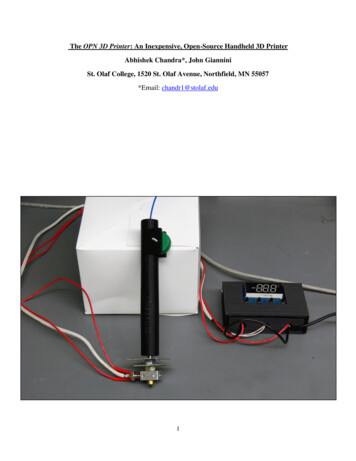
Step 6: Use epoxy glue to stick the two printed gear pieces to the spur gear such that the raised lipson the printed gears touch either side of the spur gear and their openings are continuous. (Fig.18)Place the complete gear mechanism in the opening at the top of the printed handle piece,aligning the holes in the center of the gear mechanism with the holes in the lips of the handlepiece.Run a 4.0mm steel slot screw through the continuous opening such that the complete gearmechanism is supported by the handle’s lips and is allowed to freely rotate.Screw a 4.4mm steel hex nut onto the protruding slot screw, creating a secure axle. (Fig. 1920)Figure 18: This image shows the fully assembled gear mechanism.21
Figure 19: This image shows the correct assembly of the gear mechanism in the handle piece.22
Figure 20: This image shows the fully assembled OPN 3D Printer.23
Using the OPN 3D PrinterUsing the OPN 3D Printer safely and effectively requires an understanding of both the digitalthermostat and the gear mechanism. To turn on the OPN 3D Printer plug the AC adapter intoany three-prong household or industrial electrical outlet.Setting the Digital Thermostat:The main window/panel displays the current real-time temperature after the power supply isplugged in.Buttons:ENT: This is the confirm key. Press it once to select a setting value. Holding the key forfive seconds will turn the thermostat on and off.Set: This is the settings key. Press it to enter the main menu at any time. : This is the plus key. Press it to increase the value or setting displayed on the panel.-: This is the minus key. Press it to decrease the value of setting displayed on the panel.Main Menu SettingsPress Set to enter the main menu. Cycle through options F1 through F5 using the or –buttons. Press SET to enter a particular setting option. Press ENT to leave the main menuF1: This option sets the desired temperature in degrees Celsius and can be adjusted usingthe or – buttons.F2: This setting sets the work model of the thermostat. H is heating. C is refrigeration.For printing, this must be set to heating (H).F3: This setting sets the hysteresis or the number of degrees the thermostat must decreasein order to function again after overheating.F4: This setting controls temperature correction. The value displayed here is the numberof degrees above or below the set desired temperature the thermostat will allow beforecorrecting to the desired temperature.F5: This setting sets the high-temperature alarm. This is setting is off by default and canbe adjusted to any temperature between 0 to 4990CCodes:LLL/HHH: This indicates that the temperature control element is either not connected ormalfunctioning.Pattern/RRR: This indicates that the current mode is set to refrigeration.24
Pattern/HHH: This indicates that the current mode is set to heating.Start Light: This light indicates that the device output has started and the relay has beenclosed.Using the Gear Mechanism:The OPN 3D Printer is designed to accommodate any 1.75mm filament. However, ABSor PLA filament is recommended. Once the device has been turned on, the digital thermostatmust be set according to the recommended values for the filament in use. Once the appropriatetemperature is reached a piece of the desired filament at least 20cms in length should be fedthrough the opening at the top of the Handle piece. Take care that the filament is nestled in thegroove behind the gear mechanism such that the metal spur gear is in contact with the filament.Pushing down on the filament should force extrusion from the filament extruder hot end.The gear mechanism is similar to that of a standard laboratory pipette. Pushing up on thegear mechanism or turning the gear in the forward direction will push filament down towards thehot end (Fig. 21-23). The speed and force applied on the gear mechanism controls the speed offilament extrusion.If the gear mechanism does not push down filament or turn with ease, industrial greasecan be used to lubricate the axle and gear piece. If the gear mechanism is not contacting thefilament, make sure that the filament is properly nestled in the channel in the open portion of thehandle piece. This can be seen by holding the handle piece so that the gear mechanism is facingopposite to the user. Filament that has slipped out of the channel can be adjusted using a smallpick or tweezers.25
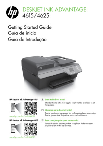
Figure 21: This image shows the correct direction of rotation of the gear mechanism forextrusion.26
Figure 22: This image shows how the OPN 3D Printer can be used to fill gaps in a print.27
Figure 23: This image shows gaps in a print filled using filament extruded by the OPN 3DPrinter.28
HazardsThere are a number of safety hazards associated with 3D printing. In particular, the 3D printingbed can become very hot when in use. Readers should exercise caution when removing anyprints from the printer bed. Also, the 3D printing process can release harmful nanoparticles intothe air, which can cause several serious health issues, including asthma attacks, respiratoryarrest, strokes, and even cardiac arrest. Readers should keep their 3D printer in a well ventilatedarea and wear proper protective equipment when operating the printer (e.g., masks or respiratorsand goggles or safety glasses to protect their respiratory systems and eyes from thesenanoparticles). We encourage readers to review the safety information pertaining to their 3Dprinter, and research to learn more about 3D printing safety. The OPN 3D Printer has a heat sinkdesigned to dissipate heat from the filament extruder hot end to avoid burning the operator. It ishighly recommended that a pipette stand be used to hold the OPN 3D Printer when not in use.Use caution when operating the device and do not touch the filament extruder hot end andattached wires when the device is in use. Upon turning off the device, allow two to three minutesfor proper cooling of the metal.DisclosuresI declare that I have no conflicts of interest related to any product, brand, company, website, orother item discussed in this manual. As well as with other open-source instruments andequipment developed by this lab, we encourage readers to improve upon the designs andmethods set forth in this manual by using other materials and equipment. We urge them to bringtheir own insights and inspirations to the project.29
References1. Atzeni, E. and Salmi, A., 2012. Economics of additive manufacturing for end-usable metalparts. The International Journal of Advanced Manufacturing Technology, 62(9), pp.11471155.2. Evans, B., 2012. Practical 3D printers: The science and art of 3D printing. Apress.3. Gross, B.C., Erkal, J.L., Lockwood, S.Y., Chen, C. and Spence, D.M., 2014. Evaluation of3D printing and its potential impact on biotechnology and the chemical sciences.4. Kietzmann, J., Pitt, L. and Berthon, P., 2015. Disruptions, decisions, and destinations: Enterthe age of 3-D printing and additive manufacturing. Business Horizons, 58(2), pp.209-215.5. Kruth, J.P., Leu, M.C. and Nakagawa, T., 1998. Progress in additive manufacturing and rapidprototyping. CIRP Annals-Manufacturing Technology, 47(2), pp.525-540.6. Lipson, H. and Kurman, M., 2013. Fabricated: The new world of 3D printing. John Wiley &Sons.7. Schubert, C., Van Langeveld, M.C. and Donoso, L.A., 2014. Innovations in 3D printing: a3D overview from optics to organs. British Journal of Ophthalmology, 98(2), pp.159-161.30
developed in the OPN Lab, our handheld 3D printer is called the OPN 3D Printer. This name is used because the device’s plans and parts are intended to be open-source and publically available for all to use. We hope that the OPN 3D Printer will be a useful tool in the developme