Transcription
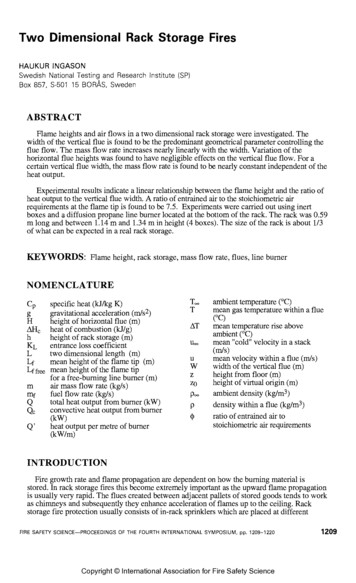
Two Dimensional Rack Storage FiresHAUKUR INGASONSwedish National Testing and Research Institute (SP)Box 857, S-501 15 BORAS. SwedenABSTRACTFlame heights and air flows in a two dimensional rack storage were investigated. Thewidth of the vertical flue is found to be the predominant geometrical parameter controlling theflue flow. The mass flow rate increases nearly linearly with the width. Variation of thehorizontal flue heights was found to have negligible effects on the vertical flue flow. For acertain vertical flue width, the mass flow rate is found to be nearly constant independent of theheat output.Experimental results indicate a linear relationship between the flame height and the ratio ofheat output to the vertical flue width. A ratio of entrained air to the stoichiometric airrequirements at the flame tip is found to be 7.5. Experiments were carried out using inertboxes and a diffusion propane line burner located at the bottom of the rack. The rack was 0.59m long and between 1.14 m and 1.34 m in height (4 boxes). The size of the rack is about 113of what can be expected in a real rack storage.KEYWORDS: Flame height, rack storage, mass flow rate, flues, line fic heat (kJ/kg K)gravitational acceleration (m/s2)height of horizontal flue (m)heat of combustion (Wg)height of rack storage (m)entrance loss coefficienttwo dimensional length (m)mean height of the flame tip (m)mean height of the flame tipfor a free-burning line burner (m)air mass flow rate (kgls)fuel flow rate (kgls)total heat output from burner (kW)convective heat output from burner(kW)heat output per metre of burner(kW1m)ambient temperature ("C)mean gas temperature within a flue("C)mean temperature rise aboveambient ("C)mean "cold" velocity in a stack(mls)mean velocity within a flue (m/s)width of the vertical flue (m)height from floor (m)height of virtual origin (m)ambient density (kglm3)density within a flue (kg/m3)ratio of entrained air tostoichiometric air requirementsINTRODUCTIONFire growth rate and flame propagation are dependent on how the burning material isstored. In rack storage fires this become extremely important as the upward flame propagationis usually very rapid. The flues created between adjacent pallets of stored goods tends to workas chimneys and subsequently they enhance acceleration of flames up to the ceiling. Rackstorage fire protection usually consists of in-rack sprinklers which are placed at differentFIRE SAFETY SCIENCE-PROCEEDINGSOF THE FOURTH INTERNATIONAL SYMPOSIUM, pp. 1209-1220Copyright International Association for Fire Safety Science1209
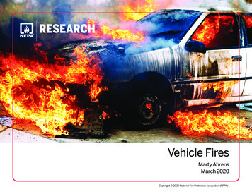
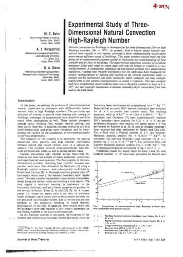
elevations in the vertical flues or on the faces of the rack storage. The efficiency of suchprotection measures depends on the geometry of the stored goods, their height, the fluespacing and the flammability of the stored goods. The time over which the in-rack sprinkleroperates is extremely important as it may be critical for control of the fire. To calculate theresponse time a knowledge of the flow conditions close to the sprinkler is necessary. Theinvestigation presented here aims at outlining the mechanisms and the parameters controllingthe flue flows in a two dimensional rack storage.Many practical problems in fire engineering require a knowledge of flame heights.Correlations to determine flame heights have been presented by a number of researchers[1,2,3,4]. The flame height correlations are applicable to freely-burning turbulent fires and notto rack storage fires. To better understand the rapid flame spread in rack storage fires it is ofinterest to outline the major parameters controlling the flame heights. Due to the complexity ofrack storage fires it was found appropriate to begin the investigation by using a simpleexperimental set-up. The experiments presented here were carried out using inert boxes in 113real scale. To further reduce the complexity of the study the rack was built in two dimensions.The present study is the first phase in the development of a model to predict flowconditions within a two dimensional rack storage. Analysis of the data and description of theexperimental set-up are given in this paper. Prior to the present study similar type of tests havebeen performed both by Ingason [S] and Karlsson et. al. [6]. These tests are to be regarded aspilot tests.EXPERIMENTSThe following combinations of parameters were used;W 50 mm, 75 mm, 100 mm with H 50 mmW 50 rnm with H 75 mmW 50 rnm with H 100 mmwhere W is the width of the vertical flue and H the height of the horizontal flue.The following four heat release rates were used in each of the combinations above;Q 18.84 kW, 24.8 kW, 34.7 kW and 44.5 kWA schematic figure of the experimental arrangement is shown in Figure 1. The rack storageconsisted of rectangular Navilite N boxes, 0.59 m long, 0.235 m high and 0.22 wide, held upby two narrow steel columns. The rack storage was two boxes wide and four boxes high. Inthe following each level of boxes will be called a "tier". Walls were put at each end of theboxes to create two dimensional conditions. Specially made wings were mounted at each wallin order to minimise the boundary effects of the air flowing in through the horizontal flues(see the plan view in Figure 1). These wings were made of plywood and extended 500 mmfrom the rack.The Navilite N plates used to build the boxes were 9.5 mm thick, which means that theboxes were almost empty, except for the strips of wood used to fasten the plates together. Thethermal data for the Navilite N is as follows; heat conductivity 0.12 Wlm 'C, specific heat 800kJ/kg and density 700-780 kglm3.Prior to the tests, the line burner was calibrated for the heat outputs used in the test series.This was done by measuring simultaneously the weight loss in a gas tube filled with propane(AH, 46.45 kJ/g) and the heat release rate from the burner by oxygen depletion calorimetry.The heat release rate was measured with a "furniture" calorimeter as described in the Nordteststandard NT Fire 032 [7].During the test series the different heat outputs were manually adjusted with aid of arotameter. A relationship had been found between the values on the rotameter and the heat
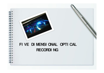
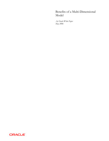
.A-AFront viewCross sectionPlan viewFIGURE 1. A 2-dimensional rack storage with non-combustable material. Dimensions areg venin mm.IIIIIIIIIIIIIH-,40,T- - -w\ 50mm stlff lnsulat onMFIGURE 2. The dimensions of the line burner are given in mm. The gas used was propane.release rate measured by the calorimeter. It has been shown in [5] that putting the line burnerinside the rack does not affect the total heat release rate compared to free burning. As this testset-up is very similar to the one presented in [5] it was thought unnecessary to measure theheat release rate from each test. The instrumentation consisted of thermocouples and bidirectional probes located at the centreline in the vertical flue at different heights. In Figure 3the instrumentation layout is shown. To avoid influence of the bi-directional probes on eachother they were mounted in a staggered form. To each bi-directional pressure flow probe(D 16 mm and L 32 mm) was attached a type K thermocouple with a diameter of 0.25 mm.The thermocouples were located about 10 mm from the edge of the bi-directional probe head.Within the rack a total of 8 measuring probes were used for velocity and temperaturemeasurements whereas 4 probes were mounted above the rack. The probes used in theanalysis presented here are shown in Figure 3.Data were collected in a data acquisition system. The temperature was recorded by a 3530ORION Data Logging Systems and stored on a Digital PDP 11/23 Plus main-frame computer.Every 10 seconds the temperatures were recorded during a period of 6 minutes (steady statetests). The pressure difference for the velocity measurements was recorded using a pressurescanner and the data were stored on a PC. The scanning time was 23 seconds. Therelationship between pressure and velocity includes corrections for variation in the Reynoldsnumber according to calibration curves reported in [8]. The results were averaged over thetime interval during which the measured gas temperatures and velocities were reasonablysteady. It was found that this time was about four minutes, i.e. the final four of the six
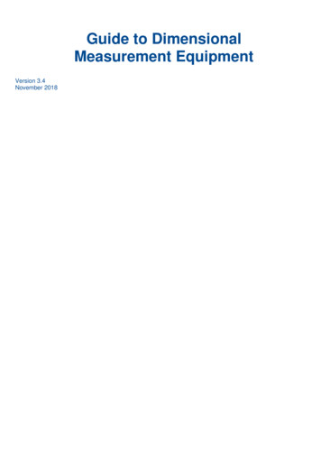
0.25 mm K-type thermocouple anda bl-directional probe (D l 6 mm) inthe centre of the flueFIGURE 3. The figure shows the layout of the instruments used. All dimensions are in mm.minutes of the test. In the beginning of the test the walls were relatively cold causing largeheat losses. After about 2 minutes the gas temperature was found to increase moderately untilthe end of the test. The temperature measurements were corrected for radiation effects. In [5] aformula for the correction of a 0.25 mm thermocouple is given.DATA ANALYSIS AND RESULTSThe mean height of the flame tip was determined. The problem with the tests presentedhere is that the flames were mostly hidden by the boxes. Consequently, the determination ofthe flame height was rather subjective. In those cases where the mean flame tip, see Figure 4,was hidden above approximately half the box height, the flame height was determined byobserve the fluctuations of the flame strips through the horizontal flue above the box. Usingthe highest top of the flame strips (existed periodically) as a reference a judgement was madeof the distance below the top of the box were most of the flame strips were expected to exist.The distance was measured by a measuring stick placed in front of the rack. In the cases werethe mean flame height was expected to be below half the box height, the flame strips wereobserved through the horizontal flue below the box. Using the lowest top of the flame strips(existed periodically) as a reference a judgement was made of the distance above the bottom ofthe box were most of the flame strips were expected to exist. If there was any doubt about theheight of the flame strips an extra observation was made above the rack (see Figure 4).The measured flame heights are presented in Table 1. The fluctuations of the flame tipwithin the rack were much smaller than those of the freely burning line burner. The accuracyof the visual flame height determination here is deemed to be about I- 50 mm. Also, forcomparison, flame height data for a freely burning line burner is given. The height of thevisual flame tip was averaged by eye. From Table 1 it is noticed that for the smallest fluewidth, W 50 mm, the ratio LfLf free between the flame height in a rack storage and the heightfor a freely.burning line burner is in the range 2.5 - 2.9. At the doubled width, W 100 mm,the corresponding figures are 1.9 - 2.3. It is found from the experimental data, that the massflow rate (entrained air) at each tier is nearly doubled when the flue width is doubled. This canbe indirectly seen in Figure 6 where the dimensionless stack height (z/h) versus the ratio of
mass flow rate to the flue width (m/W) is plotted. This increase in entrained air may explainthe reduction of the ratio Lfnfk,, when the flue width is increased.estimation by eyeabove the rackLf mean fl ame ti pFIGURE4. The flames are mostly hidden by the boxes and thus a subjective estimation ofthe mean height of the flame tip was made.TABLE 1 The table give the observed flame heights within the rack and for a freely burningline burner. The data were obtained by "visually" averaging the height of the flame tip.TEMPERATURES WITHIN THE VERTICAL FLUEIn Figure 5 the temperature at the centreline of the vertical flue is plotted as a function ofthe dimensionless flame height z/Lf where z is the height of the temperature measurementsabove floor and Lf is the mean height of the flame tip. In the literature [9,10] the temperaturedistribution within the flame region of a free burning axisymmetric buoyant diffusion flame
can be found. Based on MaCaffrey's data 191, Drysdale 1111 discusses the axial temperaturedistribution in two different flame regions. For freely burning methane fires the averagecentreline temperature is approximately constant (AT 800 C) in the persistent flaming (steadyyellow) region (214215 0.08) but falls in the region of intermittent flaming (0.08 z/Q2/5 0.2) to about 320 C at the boundary of the buoyant plume (z/ 2/5 0.2).Thus, one wouldexpect the temperature at the average flame height as defined by Zukoski et al.[12,13] (visualaveraged by eye or the distance where the intermittency has declined to 112) to lie in the regionof 500-600". Heskestad 1211 plotted a centreline temperature in logarithmic coordinates in aform attributable to MaCaffrey 191, and Kung and Stavrianidis [22], throughout the length ofthe plume, including the flames. The mean flame height corresponded to values in the 0.15 to0.2 range for ( Z - Z ) / Qand an/ associated temperature rise (AT) of about 500 "C wasindicated. In the range (z-zo)/Q,2/5 0.1 the average centreline temperature is found to benearly constant (AT 900 C).FIGURE 5. The temperature at the centreline of the vertical flue plotted as a function of thedimensionless flame height z/Lf for different flue widths, W.In Figure 5 we observe that similar tendencies are obtained here, i.e. there are two differenttemperature regions within the flame. Below about half the flame height the temperature isnearly constant and above it starts to decrease. The temperature T at the mean flame tip (asdefined in Figure 4), i.e. z L f 1, is found by a curve fit (least square) for the measuringpoints zLgO.5 to be 450 C. By averaging the data in the region zLf 0.5, i.e. theapproximate region with steady yellow flames, the temperature T is found to be 870 C, orAT 850 C. From Figure 5 it is observed that narrower flue widths tend to give highertemperatures than wider flues.MASS FLOW RATE WITHIN THE VERTICAL FLUEThe mass flow rate in the vertical flue can be expressed aswhere T, is the ambient temperature, T is the gas temperature and u is t
A 2-dimensional rack storage with non-combustable material. Dimensions g ven in mm. I I I I I I I I I I I I I H _ - - ,40, --- T w \ 50 mm stlff lnsulat on M are FIGURE 2. The dimensions of the line burner are given in mm. The gas used was propane. release rate measured by the calorimeter. It has been shown in [5] that putting the line burner inside the rack does not affect the total heat .