Transcription
Instruction Manual 8186/1/06Veri-Flame Single BurnerMonitoring SystemModel 5600Version 1.21Modulation ModelNo Purge ModelPurge Model
CopyrightCopyright 2006 by Eclipse, Inc. All rights reserved worldwide. This publication isprotected by federal regulation and shall not be copied, distributed, transmitted,transcribed or translated into any human or computer language, in any formor by any means, to any third parties, without the express written consent ofEclipse, Inc., Rockford, Illinois, U.S.A.Disclaimer noticeIn accordance with the manufacturer’s policy of continual product improve ment,the product presented in this brochure is subject to change without notice orobligation.The material in this manual is believed adequate for the intended use of theproduct. If the product is used for purposes other than those specified herein,confirmation of validity and suitability must be obtained. Eclipse, Inc. warrantsthat the product itself does not infringe upon any United States patents. Nofurther warranty is expressed or implied.We have made every effort to make this manual as accurate and complete aspossible. Should you find errors or omissions, please bring them to our attentionso that we may correct them. In this way we hope to improve our productdocumentation for the benefit of our customers. Please send your correctionsand comments to our Marketing Communications Manager.Liability andWarrantyIt must be understood that Eclipse’s liability for its products, whether due tobreach of warranty, negligence, strict liability, or otherwise, is limited to thefurnishing of burner monitoring system replacement parts and Eclipse willnot be liable for any other injury, loss, damage or expenses, whether direct orconsequential, including but not limited to loss of use, income of, or damage tomaterial arising in connection with the sale, installation, use of, inability to useor the repair or replacement of Eclipse products.Eclipse, Inc., for a period of one year from shipment, warrants each Veri-Flameburner monitoring system to the original purchaser to be free from defectsin material and workmanship under normal use as defined hereafter. Anyoperation expressly prohibited in this Guide, any adjustment or assemblyprocedures not recommended or authorized in these instructions, shall voidthe warranty. Eclipse Veri-Flame Instruction Manual 818 -6/06
About this manualAudienceThis manual has been written for the people who select and install the productand the technicians who work on it. They are expected to have previous experience with this kind of equipment.ScopeThis manual contains essential information for the proper installation and operation of the Eclipse Veri-Flame Burner Monitoring System.Following the instructions in this manual should assure trouble-free installation andoperation of the monitoring system. Read this manual carefully. Make sure thatyou understand its structure and contents. Obey all the safety instructions.Do not deviate from any instructions or application limits in this manual withoutwritten consent from Eclipse Combustion, Inc.If you do not understand any part of the information in this manual, do notcontinue. Contact your Eclipse sales office or Eclipse Combustion, Inc., Rockford, Illinois.DocumentConventionsThere are several special symbols in this document. You must know their meaning and importance.The explanation of these symbols follows. Please read it thoroughly.Danger:Indicates hazards or unsafe practices which WILL result in severepersonal injury or even death.Only qualified and well trained personnel are allowed to carry outthese instructions or procedures.Act with great care and follow the instructions.Warning:Indicates hazards or unsafe practices which could result in severepersonal injury or damage.Act with great care and follow the instructions.Caution:Indicates hazards or unsafe practices which could result in damage to the machineor minor personal injury.Act carefully.Note:Indicates an important part of the text.Read the text thoroughly.Eclipse Veri-Flame Instruction Manual 818 -6/06
How to get helpIf you need help, you can contact your local Eclipse Combustion sales office.You can also contact Eclipse Combustion, Inc. at:1665 Elmwood RoadRockford, Illinois 61103 USAPhone: 815-877-3031Fax: 815-877-3336E-mail: eclipse@eclipsenet.comhttp://www.eclipsenet.com Eclipse Veri-Flame Instruction Manual 818 -6/06
Table of ContentsAbout this manual .3Table of contents .51Introduction .882Specifications .99993DIP Switch Selection .1212121212134Function Summary .14141414141414141415151515Product .Introduction.DIP Switch Location.DIP Switch Access.No Purge DIP Switch Settings.Modulation & Purge DIP Switch Settings.Introduction.Standard Features.Combustion Air Flow Check.Main Fuel Valve Closed switch.Low Fire Start.High Fire/High Fire Purge Check.Recycle Mode.Pilot Test Mode.Interrupted or Intermittent Pilot.Post Purge.Spark, Pilot Flame & Main Flame Separation.System Error & Lockout Conditions.High to Low Fire Purge Modulation Capability with High to LowFire Position Switch Interlocks.Eclipse Veri-Flame Instruction Manual 818 -6/0616
4Optional Features.Pilot Test Mode Sequence.Air Switch Input Hold.Remote Display & Power Supply.Status Lights & Push-buttons.Interlocks Closed.Air Failure.System Error.Burner On.Flame Failure.Low Fire.High System Installation . .181818181819191919192020216Sensor Installation .2424242525257Test Procedures .2626262627272727Introduction.Interlocks and Limit Switch Input.Combustion Air Switch Input.Ignition Wiring.Low Fire Input.Main Valve Closed switch.High Fire Input.Remote Reset.Remote Display & Power Supply.Purge and No Purge Wiring Diagram (Figure 5.1).Modulation Wiring Diagram (Figure 5.2).Typical Connections for all Models (Figure 5.3).Introduction.Sensor Wiring.Flame Rods.Scanners.Scanner Sighting Considerations.Introduction.Flame Signal Strength.Minimum Pilot Test.Pilot Flame Failure Test.Main Flame Failure Test.Spark Sighting Test.Limits & Interlock Tests.Eclipse Veri-Flame Instruction Manual 818 -6/06
8Maintenance & Troubleshooting .282828282829303031329Remote Display Messages .33333438Appendix . .414142Introduction.Maintenance.Monthly Checklist.Yearly Checklist.Troubleshooting.LED Status.LED Status & Conditions for No Purge Models (Table 8.1).LED Status & Conditions for Purge Models (Table 8.2).LED Status & Conditions for Modulation Models (Table 8.3).Introduction.Veri-Flame Operating Sequence (Table 9.1) .Remote Display Diagnostic Messages (Table 9.2).Conversion Factors.Illustrated Parts List .Eclipse Veri-Flame Instruction Manual 818 -6/06
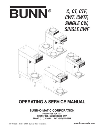
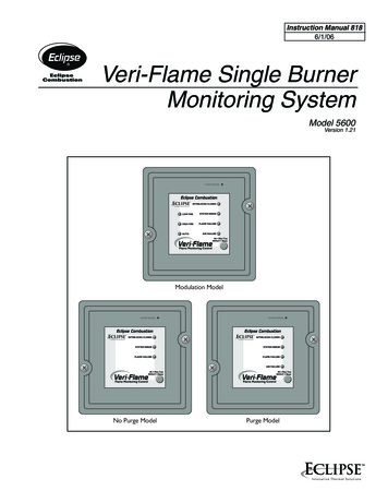
Introduction1ProductDescriptionThe Eclipse Combustion Veri-Flame Single Burner Monitoring System controlsthe start-up sequence and monitors the flame of single gas, oil, or combi na tiongas/oil burners. There are three different models to the Veri-Flame line: the nopurge, the purge and the modulation models. Each model features field selectable trial for ignition (TFI). Each model is also available for use with four types offlame sensor: ultraviolet (UV), self-check UV, solid state UV/IR and flame rod.Required components are the Veri-Flame, matching wiring base and a flamesensor. Optional components include a remote display and cable, tester, andvarious scannner accessories.The Veri-Flame No Purge and Purge models are available in three differentseries—5602, 5603 and 5605. The 5602 Series is UL listed, CSA certified, FMapproved and GE GAP acceptable; the 5605 Series is UL listed, FM approvedand GE GAP acceptable. The 5603 Series is for 240VAC applications and isFM approved. Please see instruction manual 818-2 for European CE markedversions.The Veri-Flame Modulation model is available in two different series: 5602and 5603. Both series are capable of modulation (high and low fire purging).The5602 Series is UL listed, CSA certified, FM approved and GE GAP acceptable.The 5603 Series is for 240VAC and is FM approved.Figure 1 .1 Veri-Flame Single Burner Monitoring System(Purge Unit Shown) Eclipse Veri-Flame Instruction Manual 818 -6/06
Specifications2IntroductionThis section gives a detailed overview of Veri-Flame specifications ture RangesDESCRIPTION Series 5602 & 5605: 120 VAC ( 10%, -15%), 50/60 Hz standard.Series 5603: 240 VAC ( 10%, -15%), 50/60 Hz standard.Internal power consumption: 12 VA (excluding external connected loads).UnitModel Nos.Temperature RangeVeri-FlameAll Models-40 to 60 C (-40 to 140 F)90 U.V. Scanner5600-90A-20 to 60 C(0 to 140 F)U.V. Scanner5600-91-20 to 125 C (0 to 257 F)NEMA4 UV Scanner5600-91N4-20 to 125 C (0 to 257 F)UV/IR Scanner5600-92SC-20 to 80 C (0 to 176 F)Self-Check U.V.5602-91-20 to 60 C (0 to 140 F)Remote Display5602DBP0 to 50 C (32 to 122 F)Flame Failure Response3 seconds 0.5 seconds.Trial For Ignition (TFI)No Purge & Purge Models:Series 5602 & 5603: 5 or 10 seconds selectable.Series 5605: 10 or 15 seconds selectable.Modulating Model: 5 or 10 seconds selectablePilot Interrupt (if selected)10 seconds.Purge TimeSelectable from 0-225 seconds in 15 second increments.Output Ratings for 120 VAC(maximum total connectedload not to exceed 15 amps)*FunctionGas ValveIgnitionMotor or ContactorControl SignalOutput Ratings for 240 VAC(maximum total connectedload not to exceed 15 amps)*Terminals3, 548A, 10, 11, 12, 13FunctionValves, IgnitionMotors or ContactorAlarmControlUL, CSAInductive Load175VA, 1/10 HP375 VA470 VA, 1/2 HP175VATerminals3, 4, 5,8A10, 11, 12, 13Relay Contact RatingResistive Load10 amps10 amps16 amps10 ampsRelay Contact RatingResistive Load5 amps16 amps5 amps5 amps*Resistive loads have inrush currents approximately the same as steady state operation. The inductive inrush current mustbe less than 10 timesthe rating. The inrush current must not be applied more than once every 15 seconds.(continued onto next page)Eclipse Veri-Flame Instruction Manual 818 -6/06
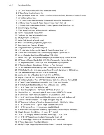
Specifications (continued)ParameterDescription No Purge & Purge Models:Series 5602: UL listed, CSA certified, FM approved and GE GAP acceptable.Series 5603: FM approved.Series 5605: UL listed, FM approved and GE GAP acceptable. Modulating Models:Series 5602: UL recognized (must be mounted in panel), CSA certified, FMapproved and GE GAP acceptable.Series 5603: FM Approved.Approvals(See chart below.)Shipping Weight 1.4 kilograms (3 lbs.) for all Veri-Flame models. 0.9 kilograms (2 lbs.) for Models 5602-10 & 5602-10-1 bases. 1.2 kilograms (2.6 lbs.) for Model 5602-40 base.Approval InformationUL Listed, File MP1537UL Recognized, File MP1537CSA Certified, File 007989FM Approved, File 3013812DimensionsVeri-Flame Unit/All Models76mm(3")133mm(5-1/4") SquareVeri-Flame Bases/Purge & No Purge ModelsModel Number 5602-105.5mm(7/32") Dia.MountingHoles (4)127mm(5")Square38mm(1-1/2")10Model Number 5602-10-1127mm(5")SquareKnockouts(10) for13mm (1/2"Conduit102mm(4") Square13mm(1/2")Eclipse Veri-Flame Instruction Manual 818 -6/06102mm(4") Square19mm(3/4")124mm(4-7/8")38mm(1-1/2")
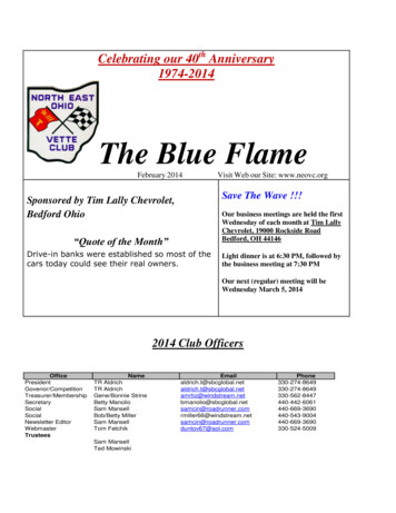
Dimensions (continued)Veri-Flame/Modulating Model with Base Model Number 5602-4024mm(15/16")171mm(6-3/4")25mm(1")1 2 3 4 5 6 7 8 A D S2 S1 10 11 12 1340mm(1-9/16")10mm (3/8")5mm (3/16")213mm (8-3/8")116mm(4-9/16")Remote Display Model Number 5602-DBP102mm(4") ContrastAdjustmentScrewMountingBracket &Screw (2) Alternate Mounting LocationsWiringTerminals (2)Eclipse Veri-Flame Instruction Manual 818 -6/0611
DIP Switch Selection3IntroductionThis section details the location, selection and description of the Veri-FlameDIP switches, which allow for sequence and timing functions as well as systemconfiguration.CautionTo avoid electric shock, shut off the power supply when installingor removing any control device. Flame monitoring systems mustbe installed by a qualified, licensed technician.12DIP Switch LocationAll of the DIP switches are located in the back of each Veri-Flame unit (see Figure3.1 on page 13, or the photograph on page 8).DIP Switch AccessTo gain access to the DIP switches, the Veri-Flame must be separated from theback box (for visual reference, please refer to “Dimensions” on page 10). Thisseparation will expose the DIP switches on the back of the Veri-Flame unit.No PurgeDIP Switch SettingsNo Purge models of the Veri-Flame only use three of the eight DIP switches, asshown in the labels in Figure 3.2 on
The Eclipse Combustion Veri-Flame Single Burner Monitoring System controls the start-up sequence and monitors the flame of single gas, oil, or combination gas/oil burners. There are three different models to the Veri-Flame line: the no purge, the purge and the modulation models. Each m