Transcription
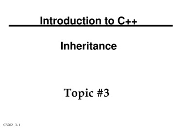
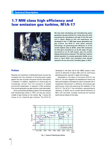
Technical Description1.7 MW class high efficiency andlow emission gas turbine, M1A-17We have been developing and manufacturing powergeneration-use gas turbines for a long time ever sincepioneering the manufacture and sale of the first suchunit in Japan. Based on this rich experience, wedeveloped a new 1.7 MW class power generation-usegas turbine, the M1A-17, with latest analysistechnology. Its generating-end efficiency is of theworld’s highest class at 26.0%, while NOx emissionsare 52.5 ppm converted on an O2 0% basis (15 ppmconverted on an O 2 15% basis), also the world’shighest performance achieved. The field test machinestarted operation in a power generation facility at ourplant in April 2010, and marketed units startedoperation all over the world, including Japan, in 2012.PrefaceRecently, the importance of distributed power sources hasincreased from the viewpoint of ensuring power supplyagainst the loss of power and power service interruptionsin disasters. In addition, regulations on exhaust gas areincreasingly stricter from the viewpoint of globalenvironment preservation. A reduction in NOx emissionsfrom power generation-use gas turbines is also demanded.Since successfully developing Japan’s first domesticallybuilt industrial gas turbine in 1972, we have put variousmodels of gas turbines on the market. Fig. 1 shows thelineup of our industrial gas turbines. The M1A-13,developed in the latter half of the 1980s, boasts a trackrecord of deliveries of about 400 units for continuousgenerating power use both in Japan and overseas.Developed on the base of the proven M1A-13, theM1A-171) not only integrates the development history andbasic technologies of Kawasaki but also is endowed with asubstantial improvement in efficiency and exhaust gasperformance while still preserving the reliability of theM1A-13. The M1A-17 has exhibited a generating-endefficiency of 26.0% and an overall thermal efficiency of80% with the boiler included, achieving the top-levelperformance indexes of this class.Output (MW)10050L20A105M7A-01M7A-02M1A-23M1A-01 .050.011975 se-load modelEmergency model2000200520102015(year)Fig. 1 Lineup of industrial gas turbines45p45 50 173E TR-06.indd 4513.4.25 11:08:55 AM
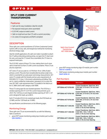
1 Overview of the M1A-17The M1A-17 is composed of a two-stage centrifugalcompressor, a three-stage axial flow turbine, and a singlecan-type combustor as its main components. The modelcan be equipped with a diffusion combustor or a dry lowemission (DLE) combustor; the model equipped with aDLE combustor is distinguished as the M1A-17D. Fig. 2shows a cut model of the M1A-17D and Table 1 the maincharacteristics and cogeneration performance data. Thefeatures of the M1A-17 are described below.(3) High reliabilityThe basic structures of the rotor and casing of the M1A-17are the same as those of the highly reliable M1A-13. Tocarry on the overall system reliability from the predecessormodel, the same number of revolutions and the samebearings as the M1A-13 have been adopted; the peripheraldevices were proven on other models.Combustor(1) High efficiencyThanks to measures to improve the efficiencies ofindividual elements described hereafter, the M1A-17 hasachieved the world’s top level of generating-end efficiencyat 26.0%. And, since the exhaust gas temperature is onthe same level as that of conventional machines, it hasattained a high overall thermal efficiency of 80% as acogeneration system that produces, in addition toelectricity, steam by using the exhaust gas.(2) Low emissionThe DLE combustor incorporates Kawasaki’s provensystem used in the M7A, inheriting the high reliability ofthe model. Equipped with a DLE combustor, the M1A-17has achieved the world’s top-level of low NOx performanceat 15 ppm (O2 15%).ExhaustdiffuserTurbineCompressorFig. 2 Cut model of M1A-17D gas turbineTable 1 Main specifications and performances of M1A-13D and M1A-17DModelM1A-13DTypeSimple open cycle, single-shaft typeCompressorTwo-stage centrifugal typeTurbineThree-stage axial flow typeCombustorSingle-can-type (DLE)Generating-end output (kW)3Fuel consumption (m N/h)M1A-17D1,4501,630617629Quantity of steam supplied (kg/h)5,1005,000Generating-end efficiency (%)23.626.0Heat recovery efficiency (%)56.154.1Overall thermal efficiency (%)79.780.1NOx value (ppm, O2 15%) (Operating range)NOx 25 (85〜100%)NOx 15 (70〜100%)CO value (ppm, O2 15%) (Operating range)NOx 50 (85〜100%)NOx 80 (70〜100%) Conditions for calculating performance values Intake temperature: 15 CAtmospheric pressure: 101.3 kPa (At 0 m elevation)Intake/Exhaust pressure loss: 0.98/2.45 kPaFuel: Methane 100%Generator efficiency: 95%Measures for NOx: Lean premixed combustionHeat recovery steam generator: Steam pressure 0.83 MPaG;Water supply temperature: 80 CKawasaki Technical Review No.173 July 2013 46p45 50 173E TR-06.indd 4613.4.25 11:08:56 AM
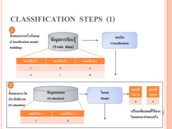
Technical DescriptionMachnumberHighTip thinningLowstnd(a) 1 stage compressor(b) 2 stage compressorFig. 3 CFD results of compressor internal flowsFig. 4 Tip thinning structure2 D esign improvements of individualelements(1) CompressorThis model adopts a two-stage centrifugal compressor. Inthe past, the application of CFD analysis was limited to thedesign of impellers, which are rotating bodies. This time,however, CFD analysis was applied to parts on thestationary side to carry out an integrated analysis of rotatingand stationary bodies for the purpose of optimizing thepassage shape so as to prevent reverse flow in thepassages of stationary bodies. Fig. 3 shows examplesfrom an analysis of internal flow in the first and the secondstage. Using this analysis technology has made it possibleto maximize the efficiency of centrifugal compressors.(2) TurbineThe turbine is a three-stage axial flow type and providedwith cooling blades in the first stage. In designing thisturbine, a tip* thinning structure (Fig. 4) was adopted as astructural feature for reducing leak loss, while a lowexpansion material was adopted for the turbine casing as amaterial feature for minimizing the tip clearance** in ratedoperation. This helped reduce leaking from the blade tips,allowing more fluid energy to be recovered by the turbine.In terms of aerodynamics, the latest CFD tools were usedto separately analyze the individual stages, and then allstages were analyzed with the aim of optimizing thepassage shape and distribution of work between thestages. Fig. 5 shows the result of the CFD analysis on allstages.* Tip: Tip of turbine blade** T ip clearance: Clearance between the tip of blade and theturbine shroud that covers the bladest1 stagenozzlest1 stagebladend2 stagenozzlend2 stagebladerd3 stagenozzlerd3 stagebladeMach numberHighLowFig. 5 CFD results of all turbine stages47p45 50 173E TR-06.indd 4713.4.25 11:08:58 AM
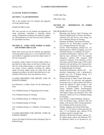
Strutrd3 stage bladeFlow speedHighrdStrut3 stage bladeFlow speedHighLowLow(a) M1A-13(b) M1A-17Fig. 6 CFD results of exhaust diffuser(3) Exhaust diffuserThe exhaust diffuser is used to discharge exhaust gaswhile expanding the flow passage to reduce the flowspeed and recover static pressure. Struts are provided inthe flow passage to hold bearing parts and others arrayedon the inside diameter side. Since the struts are providedin the exhaust gas passage, their shape, number, andarrangement affect the performance of the exhaustdiffuser greatly. In the M1A-17, CFD-based flow analysiswas used to study the arrangement and shape of thestruts, while the pressure loss was reduced by minimizingthe reverse flow domain. Fig. 6 shows examples from theCFD-based analysis of the exhaust diffuser used in theM1A-13 and M1A-17. The illustration shows a smallerseparation of flow and areas of reverse flow in the M1A-17than in the M1A-13, which comes as a result of reducingthe number of struts and other measures.(4) DLE combustorThe combustor is based on lean premixed and asupplemental combustion method, both of which havebeen proven with our products. The combustor has threeburners: a pilot burner, a main burner, and supplementalburners (Fig. 7). The pilot burner is used mostly for ignitionand low load, while the main burner and the supplementalburners are used at low NOx operation. Keeping the fuelconcentration distribution as homogeneous as possible inthe combustion zone is effective towards reducingSupplemental burnersPilot burnerLean premixcombustionSupplementalcombustionMain burnerFig. 7 Dry Low Emission combustorKawasaki Technical Review No.173 July 2013 48p45 50 173E TR-06.indd 4813.4.25 11:09:00 AM
Technical DescriptionNOxCO25250DLE load range15200150NOx guaranteed value10100CO guaranteed value5060CO (O2 15%, ppm)NOx (O2 15%, ppm)2050657075808590Load ratio (%)951000105Fig. 8 NOx emission characteristicsemissions. For this purpose, CFD analysis was used tooptimize the shape of the burner and flow passage so thatair and fuel are mixed efficiently in the burner section. Incombustor unit tests and engine tests, an NOx value nogreater than 15 ppm (O 2 15%) was attained, thusimproving NOx exhaust performance by about 50% incomparison with the M1A-13D. Fig. 8 shows the NOxexhaust characteristics.3 Field testTo determine the reliability of the M1A-17D, a field testwas started at a power station in one of our plants in April2010 (Fig. 9). The turbine is operated with the DLEcombustor. Operation exceeded 8,000 hours in August2012 and continues smoothly without problems.Fig. 9 Electric power plant at Akashi WorksTable 2 M1A-17D track record of deliveriesDelivered toCountry nameFuelWaste heat utilizationEnergy supply company ASwitzerlandNatural gasBoilerEnergy supply company BUSANatural gasBoilerChemicals manufacturing companyGermanyNatural gasBoilerFood processing company A, No.1 unitGermanyNatural gasBoilerFood processing company A, No.2 unitGermanyNatural gasBoilerMetal manufacturing companyGermanyNatural gasBoilerPaper manufacturing companyJapanCity gasBoilerConstruction materials manufacturing company A,No.1 unitJapanCity gasDrying ovenConstruction materials manufacturing company A,No.2 unitJapanCity gasDrying ovenConstruction materials manufacturing company BJapanCity gasDrying oven49p45 50 173E TR-06.indd 4913.4.25 11:09:01 AM
Yasufumi HosokawaIndustrial Gas Turbine Engineering Department,Engineering Center,Gas Turbine Division,Gas Turbine & Machinery CompanyMakoto GoudaSolution Engineering Department,Energy Solution Division,Gas Turbine & Machinery CompanyYoshihiro YamasakiIndustrial Gas Turbine Engineering Department,Engineering Center,Gas Turbine Division,Gas Turbine & Machinery CompanyYoshiaki KusumotoIndustrial Gas Turbine Engineering Department,Engineering Center,Gas Turbine Division,Gas Turbine & Machinery CompanyFig. 10 M1A-17D package (Switzerland)Daisuke UemuraIndustrial Gas Turbine Engineering Department,Engineering Center,Gas Turbine Division,Gas Turbine & Machinery Company4 Mass-production unitsThe M1A-17 was put on the market in April 2010. Sincethe first mass-produced unit was commissioned in April2012, 10 units have been shipped as of June 2012. Table 2shows the track record of deliveries, and Fig. 10 thepackage of the first mass-produced unit destined forSwitzerland.Naoki KanazawaTechnology Department,Engineering Center,Gas Turbine Division,Gas Turbine & Machinery CompanyAtsushi NorimotoQuality Assurance Department,Gas Turbine Division,Gas Turbine & Machinery CompanyConcluding remarksCarrying on the reliability proven in its predecessormachines, the M1A-17 incorporates state-of-the-artperformance-enhancing technologies and substantiallyimproves thermal efficiency through an improvement inefficiency performance of individual elements. The turbinealso has realized a low emissions level of the world’s topclass. We will continue demonstrating the reliability of itsproducts in field tests, as well as striving for furtherimprovement with the aim of contributing to the effectiveuse of energy and the reduction in environmental loading.Reference1) Y . Hosokawa, M. Gouda, Y. Yamasaki, and A. Norimoto:“Development of 1.7 MW Class High Efficiency GasTurbine, M1A-17,” Asian Congress on Gas Turbines,2012.Kawasaki Technical Review No.173 July 2013 50p45 50 173E TR-06.indd 5013.4.25 11:09:03 AM
3rd stage blade 3rd stage blade (a) M1A-13 (b) M1A-17 Flow speed High Low Fig. 6 CFD results of exhaust diffuser Pilot burner Supplemental burners Lean premix combustion Supplemental combustion Main burner Fig. 7 Dry Low Emissio