Transcription
HOME AUTOMATIONPROJECTS WITH ARDUINOGünter SpannerThe author has over 20years experience as anelectronic design engineerin industry and hasworked for several largeconcerns. In addition tohis work as a lecturer,he has authored over 30articles and books on thesubjects of electronics,microcontrollers andsensor technology. Hehas also run successfulcourses and producedrelevant study guides. Heis a respected specialistin his field and attractsa wide audience forhis presentations andwebinars.ISBN 978-1-907920-60-8www.elektor.comThat is exactly where this book begins. It explains how a widevariety of practical projects can be built using items supplied ina single kit together with the Arduino board. This kit, called the‘RFID Starter Kit for Arduino UNO’ is not just limited to RFIDapplications but contains more than 30 components, devicesand modules covering all areas of modern electronics.In addition to more simple components such as LEDs andresistors there are also complex and sophisticated modules thatemploy the latest technology such as: A humidity sensor A multicolor LED A large LED matrix with 64 points of light A 4-character 7-segment LED display An infra red remote-controller unit A complete LC-display module A servo A stepper motor and controller module A complete RFID reader module and security tagOn top of that you will get to build precise digital thermometers,hygrometers, exposure meters and various alarm systems.There are also practical devices and applications such as afully automatic rain sensor, a sound-controlled remote controlsystem, a multifunctional weather station and so much more.All of the projects described can be built using the componentssupplied in the Elektor kit.LEARN DESIGNElektor International Media BVAn Arduino board has now become ‘the’ basic component in themaker community. No longer is an introduction to the world ofmicrocontrollers the preserve of the expert. When it comes toexpanding the capabilities of the basic Arduino board however,the developer is still largely on his own. If you really want tobuild some innovative projects it’s often necessary to get downto component level. This can present many beginners withmajor problems.HOME AUTOMATION PROJECTS WITH ARDUINO GÜNTER SPANNERUSING THE RFID STARTER KITUSING THE RFID STARTER KITHOME AUTOMATIONPROJECTS WITH ARDUINOGünter SpannerLEARN DESIGN SHARESHARELEARN DESIGN SHARE LEARN DESIGN SHARE LEARN DESIGN SHARE LEARN DESIGN SHARE LEARN DESIGN SHARE LEARN DESIGN SHARE LEARN DESIGN SHARE LEARN DESIGN SHARE LEARN DESIGN SHARE LEARN DESIGN SHARE LEARN DESI DESIGN SHARE LEARN DESIGN SHARE LEARN DESIGN SHARE LEARN DESIGN SHARE LEARN DESIGN SHARE LEARN DESIGN SHARE LEARN DESIGN SHARE LEARN DESIGN SHARE LEARN DESIGN SHARE LEARN DESIGN SHARE LEARN DESIGN SGN SHARE LEARN DESIGN SHARE LEARN DESIGN SHARE LEARN DESIGN SHARE LEARN DESIGN SHARE LEARN DESIGN SHARE LEARN DESIGN SHARE LEARN DESIGN SHARE LEARN DESIGN SHARE LEARN DESIGN SHARE LEARN DESIGN SHARE LEARN DESIGN SHARE LEARN DESIGN SHARE LEARN DESIGN SHARE LEARN DESIGN SHARE LEARN DESIGN SHARE LEARN DESIGN SHARE LEARN DESIGN SHARE LEARN DESIGN SHARE LEARN DESIGN SHARE LEARN DESIGN SHARE LEARN DES DESIGN SHARE LEARN DESIGN SHARE LEARN DESIGN SHARE LEARN DESIGN SHARE LEARN DESIGN SHARE LEARN DESIGN SHARE LEARN DESIGN SHARE LEARN DESIGN SHARE LEARN DESIGN SHARE LEARN DESIGN SHARE LEARN DESIGN S
ContentIntroduction . . . . . . . . . . . . . . . . . . . . . . . . . . . . . . . . . . . . . . . . . . . . . . . . . . . . . . . 9Chapter 1 A quick introduction to the Hard- and Software . . . . . . . . . . . . . . . . . 111.1 The first Functional Test . . . . . . . . . . . . . . . . . . . . . . . . . . . . . . . . . . . . . . . . . 141.2 Programming the Arduino . . . . . . . . . . . . . . . . . . . . . . . . . . . . . . . . . . . . . . . . 161.3 Resistors: A Basic Element of Electronics . . . . . . . . . . . . . . . . . . . . . . . . . . . . . . 191.4 Are you well connected? Jumper cables . . . . . . . . . . . . . . . . . . . . . . . . . . . . . . . 201.5 LEDs . . . . . . . . . . . . . . . . . . . . . . . . . . . . . . . . . . . . . . . . . . . . . . . . . . . . . . . 211.6 Battery power for the Arduino . . . . . . . . . . . . . . . . . . . . . . . . . . . . . . . . . . . . . 22Chapter 2 Fire up the Arduino - Projects for beginners . . . . . . . . . . . . . . . . . . . 232.1 Alarm system simulator . . . . . . . . . . . . . . . . . . . . . . . . . . . . . . . . . . . . . . . . . 232.2 SOS Emergency signal . . . . . . . . . . . . . . . . . . . . . . . . . . . . . . . . . . . . . . . . . . 232.3 Mood lighting with a multicolor LED . . . . . . . . . . . . . . . . . . . . . . . . . . . . . . . . . 242.4 Switches that Bounce . . . . . . . . . . . . . . . . . . . . . . . . . . . . . . . . . . . . . . . . . . . 262.5 Data input using a keypad . . . . . . . . . . . . . . . . . . . . . . . . . . . . . . . . . . . . . . . . 302.6 Warning signals of every pitch . . . . . . . . . . . . . . . . . . . . . . . . . . . . . . . . . . . . . 342.7 Too few port pins? You need a shift register . . . . . . . . . . . . . . . . . . . . . . . . . . . . 372.8 Binary counter . . . . . . . . . . . . . . . . . . . . . . . . . . . . . . . . . . . . . . . . . . . . . . . . 382.9 Model airfield runway lights . . . . . . . . . . . . . . . . . . . . . . . . . . . . . . . . . . . . . . . 402.10 Serial Data Output . . . . . . . . . . . . . . . . . . . . . . . . . . . . . . . . . . . . . . . . . . . . 402.11 Voltage measurement on a row of LEDs . . . . . . . . . . . . . . . . . . . . . . . . . . . . . . 42Chapter 3 Display Technology . . . . . . . . . . . . . . . . . . . . . . . . . . . . . . . . . . . . . . . 463.1 An LCD for the Arduino . . . . . . . . . . . . . . . . . . . . . . . . . . . . . . . . . . . . . . . . . . 463.2 Attention! Warning Signal Display . . . . . . . . . . . . . . . . . . . . . . . . . . . . . . . . . . . 493.3 Driving Seven-Segment Displays . . . . . . . . . . . . . . . . . . . . . . . . . . . . . . . . . . . 503.4 Pin-saving Shift Register . . . . . . . . . . . . . . . . . . . . . . . . . . . . . . . . . . . . . . . . . 553.5 Universally useful: The 4x7 segment Display Module . . . . . . . . . . . . . . . . . . . . . 573.6 A Counter Not just for beans . . . . . . . . . . . . . . . . . . . . . . . . . . . . . . . . . . . . . 593.7 The SevenSeg Library . . . . . . . . . . . . . . . . . . . . . . . . . . . . . . . . . . . . . . . . . . . 633.8 A Digital Clock . . . . . . . . . . . . . . . . . . . . . . . . . . . . . . . . . . . . . . . . . . . . . . . . 643.9 For Numbers, Characters and Icons: 8x8 Dot Matrix Display . . . . . . . . . . . . . . . . 643.10 The Running Light Spot . . . . . . . . . . . . . . . . . . . . . . . . . . . . . . . . . . . . . . . . . 67 5Arduino RFID Spanner UK 170321.indd 502-05-17 16:55
Home Automation Projects with Arduino3.11 Beaming Smileys and Glowing Icons . . . . . . . . . . . . . . . . . . . . . . . . . . . . . . . . 683.12 Mini Display using an LED Matrix . . . . . . . . . . . . . . . . . . . . . . . . . . . . . . . . . . 713.13 A Joystick-controlled light point . . . . . . . . . . . . . . . . . . . . . . . . . . . . . . . . . . . 74Chapter 4 Measuring the Environment . . . . . . . . . . . . . . . . . . . . . . . . . . . . . . . . . 774.1 Dry Out the Cellar: Hygrometer Monitors Humidity. . . . . . . . . . . . . . . . . . . . . . . 774.2 Weather Station with LC Display . . . . . . . . . . . . . . . . . . . . . . . . . . . . . . . . . . . . 804.3 Workplace Bright Enough? A Digital Lux Meter. . . . . . . . . . . . . . . . . . . . . . . . . . 82Chapter 5 Sensor Technology . . . . . . . . . . . . . . . . . . . . . . . . . . . . . . . . . . . . . . . . 865.1 The Flame Detector . . . . . . . . . . . . . . . . . . . . . . . . . . . . . . . . . . . . . . . . . . . . 875.2 Alarm system with tilt switch . . . . . . . . . . . . . . . . . . . . . . . . . . . . . . . . . . . . . . 905.3 Precise Temperature Measurement with the LM35 Sensor . . . . . . . . . . . . . . . . . . 925.4 Measuring low Temperatures . . . . . . . . . . . . . . . . . . . . . . . . . . . . . . . . . . . . . . 945.5 Shout or whisper - measure the level with a sound sensor . . . . . . . . . . . . . . . . . . 955.6 Remote Control without a Transmitter: The intelligent Clap Switch . . . . . . . . . . . . 985.7 Rain or shine? A water level sensor can alert you . . . . . . . . . . . . . . . . . . . . . . . 1005.8 Umbrella alert! – A rainfall alarm . . . . . . . . . . . . . . . . . . . . . . . . . . . . . . . . . . 102Chapter 6 Motors and Servos control the world . . . . . . . . . . . . . . . . . . . . . . . . . 1046.1 The Stepper Motor and Motor Driver Module. . . . . . . . . . . . . . . . . . . . . . . . . . 1056.2 From rotation to single steps . . . . . . . . . . . . . . . . . . . . . . . . . . . . . . . . . . . . . 1076.3 Turntable to display Jewelry or scale models . . . . . . . . . . . . . . . . . . . . . . . . . . 1096.4 Use the Joystick for Motor Control . . . . . . . . . . . . . . . . . . . . . . . . . . . . . . . . . 1096.5 The Servo as a Universal Actuator . . . . . . . . . . . . . . . . . . . . . . . . . . . . . . . . . 1106.6 Controlled Motor Power: The Servo . . . . . . . . . . . . . . . . . . . . . . . . . . . . . . . . . 1106.7 The Servo Library . . . . . . . . . . . . . . . . . . . . . . . . . . . . . . . . . . . . . . . . . . . . 1136.8 Precise Servo Control . . . . . . . . . . . . . . . . . . . . . . . . . . . . . . . . . . . . . . . . . . 113Chapter 7 Banish the Spaghetti: Control Wirelessly . . . . . . . . . . . . . . . . . . . . . 1167.1 For Convenience: Remote Control with an IR Receiver . . . . . . . . . . . . . . . . . . . 1167.2 A Remotely Contolled LED . . . . . . . . . . . . . . . . . . . . . . . . . . . . . . . . . . . . . . . 1197.3 Wireless Data Reading: The RFID module . . . . . . . . . . . . . . . . . . . . . . . . . . . . 1207.4 Contactless door entry control . . . . . . . . . . . . . . . . . . . . . . . . . . . . . . . . . . . . 1247.5 RFID Tags Store Data . . . . . . . . . . . . . . . . . . . . . . . . . . . . . . . . . . . . . . . . . . 126 6Arduino RFID Spanner UK 170321.indd 602-05-17 16:55
InhaltChapter 8 Experimental projects for Advanced Users . . . . . . . . . . . . . . . . . . . . 1298.1 Always the Right Time: The RTC Module . . . . . . . . . . . . . . . . . . . . . . . . . . . . . 1298.2 Digital clocks and timers for precise time measurements . . . . . . . . . . . . . . . . . . 1348.3 Conway’s Game of Life . . . . . . . . . . . . . . . . . . . . . . . . . . . . . . . . . . . . . . . . . 1378.4 Hello Matrix! . . . . . . . . . . . . . . . . . . . . . . . . . . . . . . . . . . . . . . . . . . . . . . . . 1408.5 Live Ticker and Running Text . . . . . . . . . . . . . . . . . . . . . . . . . . . . . . . . . . . . . 1438.6 Switching High Power Loads: The Relay Module . . . . . . . . . . . . . . . . . . . . . . . . 1468.7 Remote controlled Halogen Lamp . . . . . . . . . . . . . . . . . . . . . . . . . . . . . . . . . . 1478.8 Keypad Door Entry System . . . . . . . . . . . . . . . . . . . . . . . . . . . . . . . . . . . . . . 148Chapter 9 Principles of Arduino Programming . . . . . . . . . . . . . . . . . . . . . . . . . . 152Chapter 10 Use of Libraries . . . . . . . . . . . . . . . . . . . . . . . . . . . . . . . . . . . . . . . . 160Chapter 11 Fault finding . . . . . . . . . . . . . . . . . . . . . . . . . . . . . . . . . . . . . . . . . . . 162Chapter 12 Components and Modules . . . . . . . . . . . . . . . . . . . . . . . . . . . . . . . . 163Chapter 14 Literature . . . . . . . . . . . . . . . . . . . . . . . . . . . . . . . . . . . . . . . . . . . . . 184Chapter 15 Illustration Listing . . . . . . . . . . . . . . . . . . . . . . . . . . . . . . . . . . . . . . 185Index . . . . . . . . . . . . . . . . . . . . . . . . . . . . . . . . . . . . . . . . . . . . . . . . . . . . . . . . . . . 188 7Arduino RFID Spanner UK 170321.indd 702-05-17 16:55
IntroductionIntroductionWithout doubt the Arduino system has become ‘the’ basic component amongstelectronics communities and makers. Earlier it was necessary to begin with abare microcontroller as the basic building block of any system, now the Arduino is more and more frequently used. Armed with the Arduino system your firststeps into the world of microcontroller technology could not be made any simpler.Instead of a complex programming environment, where you would be expected to startcoding from scratch you can now work with a highly intuitive development environmentcombining pre-tested library routines to get you up and running in no time.When it comes to plugging in additional hardware to the basic Arduino board the developeris still largely on their own. There is a wealth of special expansion boards for the Arduinobut these are often only useful for some specific application areas. If you really want tobuild some innovative projects you often have to get down to component level. This presents many beginners with major problems.There are some developer’s kits which can help in this area. These contain a range of components that you can use with the Arduino to build lots of different projects and help youunderstand how they work.That is exactly the purpose of this book. It explains how a wealth of practical projects canbe built from a single kit. This kit, called the ‘RFID Starter Kit for Arduino UNO’ containsmore than 30 components, devices and modules from all areas of modern electronics.In addition to more simple components such as LEDs and resistors there are also complexand sophisticated modules that use the latest technology such as: A humidity sensorA multicolor LEDA large LED matrix with 64 points of lightA 4-character 7-segment LED displayAn infra red remote-controller unitA complete LC-display moduleAdditional special devices include: A servo A stepper motor and controller module A complete RFID reader module and security tagWith these components you can build a whole lot of different projects. For the beginner,we first start off with a few simple introductory experiments. More experienced users canon the other hand go on to build the more complex projects that are described a bit laterin the book. 9Arduino RFID Spanner UK 170321.indd 902-05-17 16:55
Home Automation Projects with ArduinoIn addition to precise digital thermometers, hygrometers, exposure meters and variousalarm systems, there are also practical devices and applications such as AAAAfully automatic plant irrigation systemsound-controlled remote control systemdigital clock with versatile display possibilitiesmultifunctional weather stationplus much more.The projects presented here could not be classed as ‘laboratory prototypes’ but are insteadpractical and useful designs, fully described with lots of hints and tips on their use in hobby,household and professional applications.All the projects can be built using the components supplied in the Elektor kit. Alternatively, most of the components can also be purchased from specialist dealers or from onlineauction sites. At the end of the book a description of these components and a source fromwhere they can be purchased is given. With this information you can replace defective orlost components.This also gives you the option to purchase components to build individual projects withoutthe the need for the entire kit. The SainSmart Boards have also been offering a cost-effective yet high-quality Arduino clone for some time now. Their boards are fully compatiblewith the classic Arduinos.All the sketches given in this book are available to download from:www.elektor.comWhen the sketch is not identical to the listing in this book the downloaded version will bethe latest version and is the one that should be used. 10Arduino RFID Spanner UK 170321.indd 1002-05-17 16:55
Chapter 1 A quick introduction to the Hard- and SoftwareChapter 1 A quick introduction to the Hard- and SoftwareIn general, ‘Arduino’ can be used to refer to the development board itself, i.e. the hardwareof which there are now many variants of the original Arduino board but we will go into thatin a little more detail below. Arduino also refers to the programming environment, togetherthey make up the ‘Arduino System’.The Arduino hardware consists of a microcontroller board. This is a circuit board or PCBon which there are several other electronic components besides the microcontroller itself.Along the two long edges of the board the Arduino has a row of header sockets commonly referred to in the text as the Arduino’s pins. The pins are used to connect the variouselectronic components to the Arduino. These components, eg pushbuttons, Light EmittingDiodes (LEDs), various sensors, potentiometers, displays, motors, servos etc. will all beused in the following chapters.There are now lots of different versions of Arduino boards which can be used with the Arduino software. This includes boards of different size all labelled with the official ‘Arduino’or ‘Genuino’ logo.In addition to the official series of boards there are a number of unofficial third party boardsor clones which are substantially cheaper than the originals. They are largely compatible interms of both hardware and software which means that electrically they produce the samesignals and they can be programmed with the Arduino IDE.The classic Arduino controller boards have names like: Arduino UNO, Arduino MEGA, Arduino Micro etc.While their corresponding clones have names such as: Seeduino UNO,Funduino MEGA,Freeduino MicroSainSmart UNO etc.The Arduino UNO (see below) is used throughout this book for all of the projects describedhere. One important compatible board called the SainSmart UNO, can also be substitutedfor the original Arduino in all the projects. 11Arduino RFID Spanner UK 170321.indd 1102-05-17 16:55
Home Automation Projects with ArduinoIllustration 1: An original Arduino UNOIn addition to all the electronic components in the kit there are also a bunch of jumperwires that are used for making fast and flexible connections between the Arduino and othercomponents. The flexible cable has a stiff pin at each end for it to plug into the Arduinoheader strips. Their flexibility makes it easy connect up large structures. Using these wireseliminates the need for time-consuming soldering. They also plug into the protyping plugboard or breadboard that we make use of here to build up more complex circuits.Their flexibility allows you to test projects and devices without having to make and unsolder joints repeateadly. This construction method has gained broad acceptance in the widerArduino community.Once the circuit idea has been tested you might wish to make a more permanent versionof the circuit using either perf board or a proper custom-made PCB.The prototyping breadboard or plug board is a really useful base on which to build up circuits. It’s particularly good for teaching and training and once the circuit has been testedand understood all the components and wires can just be unplugged and re-used later. Withcareful handling the plug board and accessories will last a long time.The following illustration shows the structure of a breadboard. The lines indicate how thecontacts are connected to each other. This arrangement makes the electrical connectionsbetween components and jumpers leads plugged into the board without the need forscrews or solder. 12Arduino RFID Spanner UK 170321.indd 1202-05-17 16:55
Chapter 2 Fire up the Arduino - Projects for beginnersChapter 2 Fire up the Arduino - Projects for beginnersNow you have been introduced to all the components and the Arduino board has alreadybeen given a functional test the fun can begin. First off we start with some simple projectswhich you can build without the need for too much additional hardware. The accompanyingsketches should also not cause any problems. They may be simple but working throughthe examples you will get to build many practical projects that you will find are very useful.2.1 Alarm system simulatorEven this first simple project has a real practical use that could save you a great deal ofstress. It is an alarm system simulator, useful as a burglar deterrent.The most basic test program for the Arduino uses the blink.ino sketch. It makes an LEDregularly flash on and off.In this sketch called flash.ino the LED remains off for three seconds and then flashes brieflyfor a tenth of a second. This is a typical signal used by car and house alarm systems toindicate that the system is armed.The flashing LED can be installed somewhere visible and with any luck it would deter anopportunist thief who would not know if this is a genuine signal from a sophisticated alarmsystem or just a decoy. Best of all, there’s no risk of a false alarm waking you up at night!The sketch looks like this:// Alarm simulator.inovoid setup(){ pinMode(13, OUTPUT);}void loop(){ digitalWrite(13, HIGH);delay(100);// turn the LED on (HIGH is the voltage level)// wait for a tenth of a seconddigitalWrite(13, LOW);// turn the LED off by making the voltage LOWdelay(3000);// wait for three seconds}2.2 SOS Emergency signalA single LED is all you need to generate an SOS signal. The three long followed by threeshort flashes is the internationally recognized signal to indicate distress. Bright LEDs canbe seen from a distance and could be a life saver should you get lost on a mountain walk.The signal is applied to the Arduino internal LED which is connected to digital pin D13 onthe Uno. An external LED can be used connected to pin 12 for example, a 1K series resistorint ledPin 13; // LED in series with 1k resistor on pin 12must be connected in series with pin D12 and the LED. 23Arduino RFID Spanner UK 170321.indd 2302-05-17 16:55
Home Automation Projects with Arduino// SOS.inoint ledPin 13; // or external LED in series with 1k resistor on pin 12int i;// declare variable ivoid setup(){pinMode(ledPin, OUTPUT);}void loop(){for (i 1; i 3; i ){digitalWrite(ledPin, HIGH);delay(500);digitalWrite(ledPin, LOW);delay(500);}delay(1000);for (i 1; i 3; i ){digitalWrite(ledPin, HIGH);delay(1500);digitalWrite(ledPin, LOW);delay(1500);}delay(1000);for (i 1; i 3; i ){digitalWrite(ledPin, HIGH);delay(500);digitalWrite(ledPin, LOW);delay(500);}delay(3000);}2.3 Mood lighting with a multicolor LEDAs well as the standard range of LED indicator lamps which only light up in one color thereis also the so-called multicolor LED. These contain three LED chips in one housing.They normally contain a Red, Green and Blue LED. They also go by the name RGB LEDs.By controlling the on to off ratio of the signal switching each LED it’s possible to producenot only the three basic colors but also all the color nuances in between, all the way up towhite light.When the colors change slowly in a predetermined sequence the effect is usually referredto as ‘mood lighting’. Here is a sketch that produces this effect: 24Arduino RFID Spanner UK 170321.indd 2402-05-17 16:55
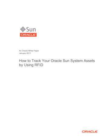
Home Automation Projects with ArduinoChapter 3 Display TechnologyDisplays are in the widest sense the interface between man and machine. Together with input devices such as pushbuttons switches and keyboards output devices are also practicallyindispensible to the operation of electronic systems. At its most basic a simple LED canbe used to indicate a condition. It can be used to indicate a particular operating mode of adevice or to alert an operator that some limit value has been exceeded, a bright red LED,for example is an effective indicator of an over-temperature condition.When you need to indicate additional information more complex displays will be necessary.The Liquid Crystal Display (LCD) is a very popular form of display technology. They can beused to show digital values and use characters to convey easily readable messages.3.1 An LCD for the ArduinoAn LCD can be used as a universal output device for the Arduino. The display included inthe kit has the following properties: It communicates via an I2C-Bus – Address range: 0x20 to 0x27 (0x20 is thedefault) White characters on a blue background Operating voltage: 5V Contrast adjustable using a pot Display size: 82 mm x 35 mm x 18 mmIllustration 29: LCD moduleWithout doubt LCDs are amongst the most important peripheral components used withmicrocontroller-based systems. They can display numbers, letters and also various special characters. They will also give your projects a more profession look. The values oftemperature, voltage levels and other measurements can be represented accurately onthe display as well as more mundane things such as time of day and text messages. 46Arduino RFID Spanner UK 170321.indd 4602-05-17 16:55
Chapter 3 Display TechnologyIllustration 30: The LCD module from the backIn contrast to LED dot-matrix displays LCDs are almost exclusively supplied with an integrated controller chip. This is because the dot-matrix LCD has a very large numberof pixels needing to be controlled. Even a relatively small 2-line 16 character display ismade up of over 1000 pixels. This would far exceed the resources available from an AVRmicrocontroller. These LCDs therefore form part of a display module with an integratedcontroller chip. One of the most popular types of controller chips is the HD44780. Thesecan be controlled with just 16 connections. A close look at the display module will revealthe single row of 16 pin header type connections along the top edge of the board.Connecting all 16 of these pins to the Arduino would use up a lot of the Arduino’s I/Ocapability. There are methods of using the display module which reduce the number ofconnections required but we would still need at least six I/O pins.Besides the large display controller chip on the display module there is also a smaller chipwhich provides the module with an I2C serial interface so the number of I/O pins requiredis now reduced to just two for controlling the display. This is an important advantageespecially for larger more complex projects which use a large number of Arduino pins.Another difference compared with the standard LCD module is that this one includes a potto control the display contrast.If you can’t see any characters on the display when you start using it, try twiddling thecontrast control pot using a small screwdriver pushed into the central slot in the pot tofind the optimal setting.With the serial interface cabling between the Arduino and display module is now down tojust four wires. GND connects to the GND pin on the microcontroller and Vcc with the 5VPin on the Arduino or Sainsmart Uno board.The connection labeled SDA on the display module connects to the Uno analog input A4and SCL to analog input A5. These pins have a double function; they can be used with 47Arduino RFID Spanner UK 170321.indd 4702-05-17 16:55
Home Automation Projects with Arduinoanalog input signals and also to provide the I2C-Interface signals. The table below showsthe four wire hookup between the Arduino and the LCD display module:LCD module pinDescriptionArduino pinArduino functionVccSupply voltage5VGNDGroundGNDSDASerial DataA4SDASCLSerial ClockA5SCLTo use the LCD module with the I2C interface you will need a library which is not preinstalled in the Arduino-IDE. You can download the library Crystal-I2C-libraryand install it in the Arduino IDE.The following illustration shows how to connect the module to the Arduino:Illustration 31: I2C LCD with the Arduino 48Arduino RFID Spanner UK 170321.indd 4802-05-17 16:55
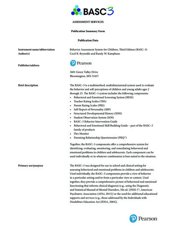
Chapter 4 Measuring the EnvironmentChapter 4 Measuring the EnvironmentMonitoring and taking measurements of our environment are some of the most importanttechnological tasks of the modern age. Whether it’s tied up with vehicle emissions, protection of the environmental or in the field of robotics. It’s becoming increasingly importantto have accurate information on the conditions of both our local and remote environments.4 .1 Dry Out the Cellar: Hygrometer Monitors Humidity .The hardware kit includes a combined temperature and humidity sensor. Along with thetwo sensors this component also includes the necessary A/D converter to provide bothmeasurements as digital values. This makes it really easy to use. Communication withthe sensor including the transfer of all measured values takes place over a single datapin. The sensor unit itself has four pins, one of which is not connected so altogether weuse just three connections, two of which are to supply power. The data signal also has apull up resistor on board.The two illustrations below show the module and its corresponding pin outs.Illustration 49: DHT11Temperature/Humidity sensorIllustration 50: The DHT11 measures Temperature and Humidity 77Arduino RFID Spanner UK 170321.indd 7702-05-17 16:56
Home Automation Projects with ArduinoThe following table shows the sensors operating temperature and humi
That is exactly where this book begins. It explains how a wide variety of practical projects can be built using items supplied in a single kit together with the Arduino board. This kit, called the ‘RFID Starter Kit for Arduino UNO’ is not just limited to RFID a