Transcription
Selection GuideFuse Characteristics, Termsand Consideration Factors
FUSEOLOGYSelection GuideFuse Characteristics,Terms and ConsiderationFactorsAbout this guideFuses are current-sensitive devices that provide reliable protection for discrete componentsor circuits by melting under current overload conditions. Choosing the right fuse for yourapplication can be an overwhelming, time-consuming process, even for a seasonedelectronics design engineer. This user-friendly Fuseology Selection Guide makes the fuseselection process quick and easy-helping you optimize the reliability and performance ofthe application.Table of ContentsPageFuse Characteristics, Terms and Consideration Factors2–4Fuse Selection Checklist5–7PTC Characteristics and Terms8–9PTC Product Applications10Typical PTC Circuit Protection Designs11StandardsPTC Selection WorksheetFuse and PTC Products Selection Guide12–141516–18Packaging and Part Numbering19Legal Disclaimers20 2014 Littelfuse, Inc.Specifications descriptions and illustrative material in this literature are as accurate as known at the time of publication,but are subject to changes without notice. Visit littelfuse.com for more information.
Fuseology Selection GuideFuse Characteristics, Terms and Consideration Factorsthese standards include: fully enclosed fuseholders, highcontact resistances, air movement, transient spikes, andchanges in connecting cablesize (diameter and length).Fuses are essentially temperature-sensitive devices. Evensmall variations from the controlled test conditions cangreatly affect the predicted life of a fuse when it is loadedto its nominal value, usually expressed as 100% of rating.The purpose of this introductory section is to promotea better understanding of both fuses and commonapplication details within circuit design.The fuses to be considered are current sensitive devicesdesigned to serve as the intentional weak link in theelectrical circuit. Their function is to provide protection ofdiscrete components, or of complete circuits, by reliablymelting under current overload conditions. This sectionwill cover some important facts about fuses, selectionconsiderations and standards.The circuit design engineer should clearly understandthat the purpose of these controlled test conditions is toenable fuse manufacturers to maintain unified performancestandards for their products, and he must account forthe variable conditions of his application. To compensatefor these variables, the circuit design engineer who isdesigning for trouble-free, long-life fuse protection in hisequipment generally loads his fuse not more than 75%of the nominal rating listed by the manufacturer,keepingin mind that overload and short circuit protection must beadequately provided for.The application guidelines and product data in this guideare intended to provide technical information that willhelp with application design. The fuse parameters andapplication concepts presented should be well understoodin order to properly select a fuse for a given application.Since these are only a few of the contributing parameters,application testing is strongly recommended and should beused to verify performance in the circuit / application.The fuses under discussion are temperature-sensitivedevices whose ratings have been established in a 25ºCambient. The fuse temperature generated by the currentpassing through the fuse increases or decreases withambient temperature change.Littelfuse reserves the right to make changes in productdesign, processes, manufacturing location and informationwithout notice. For current Littelfuse product infomation,please visit our web site at www.littelfuse.com.The ambient temperature chart in the FUSE SELECTIONCHECKLIST section illustrates the effect that ambienttemperature has on the nominal current rating of a fuse.Most traditional Slo-Blo Fuse designs use lower meltingtemperature materials and are, therefore, more sensitive toambient temperature changes.AMBIENT TEMPERATURE: Refers to the temperatureof the air immediately surrounding the fuse and is not tobe confused with “room temperature.” The fuse ambienttemperature is appreciably higher in many cases, becauseit is enclosed (as in a panel mount fuseholder) or mountednear other heat producing components, such as resistors,transformers, etc.DIMENSIONS: Unless otherwise specified, dimensionsare in inches.BREAKING CAPACITY: Also known as interrupting ratingor short circuit rating, this is the maximum approvedcurrent which the fuse can safely break at rated voltage.Please refer to the INTERRUPTING RATING definition ofthis section for additional information.The fuses in this catalog range in size from the approx.0402 chip size (.041”L .020”W .012”H) up to the 5AG, also commonly known as a”MIDGET” fuse (13/32”Dia. 11/2” Length). As new products were developedthroughout the years, fuse sizes evolved to fill the variouselectrical circuit protection needs.CURRENT RATING: The nominal amperage value of thefuse. It is established by the manufacturer as a value ofcurrent which the fuse can carry, based on a controlled setof test conditions (See RERATING section).The first fuses were simple, open-wire devices, followedin the 1890’s by Edison’s enclosure of thin wire in a lampbase to make the first plug fuse. By 1904, UnderwritersLaboratories had established size and rating specificationsto meet safety standards. The renewable type fuses andautomotive fuses appeared in 1914, and in 1927 Littelfusestarted making very low amperage fuses for the buddingelectronics industry.Catalog Fuse part numbers include series identificationand amperage ratings. Refer to the FUSE SELECTIONCHECKLIST section for guidance on making the properchoice.RERATING: For 25ºC ambient temperatures, it isrecommended that fuses be operated at no more than75% of the nominal current rating established using thecontrolled test conditions. These test conditions are part ofUL/CSA/ANCE (Mexico) 248-14 “Fuses for SupplementaryOvercurrent Protection,” whose primary objective isto specify common test standards necessary for thecontinued control of manufactured items intended forprotection against fire, etc. Some common variations of 2014 Littelfuse Fuseology Selection GuideThe fuse sizes in following chart began with the early“Automobile Glass” fuses, thus the term “AG”. Thenumbers were applied chronologically as differentmanufacturers started making a new size: “3AG,” forexample, was the third size placed on the market. Othernon-glass fuse sizes and constructions were determined byfunctional requirements, but they still retained the lengthor diameter dimensions of the glass fuses. Their2www.littelfuse.com
Fuseology Selection GuideFuse Characteristics, Terms and Consideration Factors (continued)designation was modified to AB in place of AG, indicatingthat the outer tube was constructed from Bakelite, fibre,ceramic, or a similar material other than glass. The largestsize fuse shown in the chart is the 5AG, or “MIDGET,”a name adopted from its use by the electrical industryand the National Electrical Code range which normallyrecognizes fuses of 9/16” 2” as the smallest standardfuse in use.fuses up to 200,000 amperes for the 600VAC KLK series.Information on other fuse series can be obtained from theLittelfuse.Fuses listed in accordance with UL/CSA/ANCE 248 arerequired to have an interrupting rating of 10,000 amperesat 125V, with some exceptions (See STANDARDS section)which, in many applications, provides a safety factor far inexcess of the short circuit currents available.FUSE SIZESSIZE1AG2AG3AG4AG5AG7AG8AGDIAMETER 06.250.250LENGTH (Inches)5/8–1¼1¼1½7 81NUISANCE OPENING: Nuisance opening is most oftencaused by an incomplete analysis of the circuit underconsideration.625.5881.251.251.50.8751Of all the “Selection Factors” listed in the FUSESELECTION CHECKLIST, special attention must be givento items 1, 3, and 6, namely, normal operating current,ambient temperature, and pulses.TOLERANCES: The dimensions shown in this catalogare nominal. Unless otherwise specified, tolerances areapplied as follows. Tolerances do not apply to lead lengths:For example, one prevalent cause of nuisance opening inconventional power supplies is the failure to adequatelyconsider the fuse’s nominal melting I2t rating. The fusecannot be selected solely on the basis of normal operatingcurrent and ambient temperature. In this application, thefuse’s nominal melting I2t rating must also meet the inrushcurrent requirements created by the input capacitor of thepower supply’s smoothing filter. .010” for dimensions to 2 decimal places. .005” for dimensions to 3 decimal places.Contact Littelfuse should you have questions regardingmetric system and fractional tolerances.FUSE CHARACTERISTICS: This characteristic of a fusedesign refers to how rapidly it responds to various currentoverloads. Fuse characteristics can be classified into threegeneral categories: very fast-acting, fast-acting, or Slo-Blo Fuse. The distinguishing feature of Slo-Blo fuses is thatthese fuses have additional thermal inertia designed totolerate normal initial or start-up overload pulses.The procedure for converting various waveforms intoI2t circuit demand is given in the FUSE SELECTIONCHECKLIST. For trouble-free, long-life fuse protection, it isgood design practice to select a fuse such that the I2t ofthe waveform is no more than 20% of the nominal meltingI2t rating of the fuse. Refer to the section on PULSES in theFUSE SELECTION CHECKLIST.FUSE CONSTRUCTION: Internal construction may varydepending on ampere rating. Fuse photos in this catalogshow typical construction of a particular ampere ratingwithin the fuse series.RESISTANCE: The resistance of a fuse is usually aninsignificant part of the total circuit resistance. Since theresistance of fractional amperage fuses can be severalohms, this fact should be considered when using themin low-voltage circuits. Actual values can be obtained bycontacting Littelfuse.FUSEHOLDERS: In many applications, fuses areinstalled in fuseholders. These fuses and their associatedfuseholders are not intended for operation as a “switch”for turning power “on” and “off “.Most fuses are manufactured from materials which havepositive temperature coefficients, and, therefore, it iscommon to refer to cold resistance and hot resistance(voltage drop at rated current), with actual operation beingsomewhere in between.INTERRUPTING RATING: Also known as breakingcapacity or short circuit rating, the interrupting rating isthe maximum approved current which the fuse can safelyinterrupt at rated voltage. During a fault or short circuitcondition, a fuse may receive an instantaneous overloadcurrent many times greater than its normal operatingcurrent. Safe operation requires that the fuse remain intact(no explosion or body rupture) and clear the circuit.Cold resistance is the resistance obtained using ameasuring current of no more than 10% of the fuse’snominal rated current. Values shown in this publication forcold resistance are nominal and representative. The factoryshould be consulted if this parameter is critical to thedesign analysis.Interrupting ratings may vary with fuse design and rangefrom 35 amperes for some 250VAC metric size (5 20mm) 2014 Littelfuse Fuseology Selection GuideHot resistance is the resistance calculated from the3www.littelfuse.com
Fuseology Selection GuideFuse Characteristics, Terms and Consideration Factors (continued)VOLTAGE RATING: The voltage rating, as marked on afuse, indicates that the fuse can be relied upon to safelyinterrupt its rated short circuit current in a circuit where thevoltage is equal to, or less than, its rated voltage.stabilized voltage drop across the fuse, with current equalto the nominal rated current flowing through it. Resistancedata on all Littelfuse products are available on request.Fuses can be supplied to specified controlled resistancetolerances at additional cost.This system of voltage rating is covered by N.E.C.regulations and is a requirement of UnderwritersLaboratories as a protection against fire risk. The standardvoltage ratings used by fuse manufacturers for most smalldimension and midget fuses are 32, 63, 125, 250 and 600.SOLDERING RECOMMENDATIONS: Since most fuseconstructions incorporate soldered connections, cautionshould be used when installing those fuses intended tobe soldered in place. The application of excessive heat canreflow the solder within the fuse and change its rating.Fuses are heat-sensitive components similar to semiconductors, and the use of heat sinks during soldering isoften recommended.In electronic equipment with relatively low output powersupplies, with circuit impedance limiting short circuitcurrents to values of less than ten times the current ratingof the fuse, it is common practice to specify fuses with125 or 250 volt ratings for secondary circuit protection of500 volts or higher.As mentioned previously (See RERATING section), fusesare sensitive to changes in current, not voltage, maintainingtheir “status quo” at any voltage up to the maximum ratingof the fuse. It is not until the fuse element melts andarcing occurs that the circuit voltage and available powerbecome an issue. The safe interruption of the circuit, as itrelates to circuit voltage and available power, is discussedin the section on INTERRUPTING RATING.Lead-Free Soldering Parameters (most instances):Wave Solder — 260ºC, 10 seconds maxReflow Solder — 260ºC, 30 seconds maxTo summarize, a fuse may be used at any voltage that isless than its voltage rating without detriment to its fusingcharacteristics. Please contact the factory for applicationsat voltages greater than the voltage rating.TEST SAMPLING PLAN: Because compliance with certainspecifications requires destructive testing, these tests areselected on a statistical basis for each lot manufactured.DERIVATION OF NOMINAL MELTING I2t: Laboratorytests are conducted on each fuse design to determine theamount of energy required to melt the fusing element. Thisenergy is described as nominal melting I2t and is expressedas “Ampere Squared Seconds” (A2 sec.).TIME-CURRENT CURVE: The graphical presentation ofthe fusing characteristic, time-current curves are generallyaverage curves which are presented as a design aid butare not generally considered part of the fuse specification.Time-current curves are extremely useful in defininga fuse, since fuses with the same current rating canbe represented by considerably different time-currentcurves. The fuse specification typically will include a liferequirement at 100% of rating and maximum openingtimes at overload points (usually 135% and 200% of ratingdepending on fuse standard characteristics). A time-currentcurve represents average data for the design; how ever,there may be some differences in the values for any onegiven production lot. Samples should be tested to verifyperformance, once the fuse has been selected.A pulse of current is applied to the fuse, and a timemeasurement is taken for melting to occur. If meltingdoes not occur within a short duration of about 8milliseconds (0.008 seconds) or less, the level of pulsecurrent is increased. This test procedure is repeated untilmelting of the fuse element is confined to within about 8milliseconds.The purpose of this procedure is to assure that the heatcreated has insufficient time to thermally conduct awayfrom the fuse element. That is, all of the heat energy (I2t)is used, to cause melting. Once the measurements ofcurrent (I) and time (t) are determined, it is a simple matterto calculate melting I2t. When the melting phase reachescompletion, an electrical arc occurs immediately prior tothe “opening” of the fuse element.UNDERWRITERS LABORATORIES: Reference to “Listedby Underwriters Laboratories” signifies that the fusesmeet the requirements of UL/CSA/ANCE 248-14 “Fusesfor Supplementary Overcurrent Protection”. Some 32volt fuses (automotive) in this catalog are listed underUL Standard 275. Reference to “Recognized under theComponent Program of Underwriters Laboratories”signifies that the item is recognized under the componentprogram of Underwriters Laboratories and applicationapproval is required. 2014 Littelfuse Fuseology Selection GuideClearing I2t Melting I2t arcing I2tThe nominal I2t values given in this publication pertain tothe melting phase portion of the “clearing” or “opening”.Alternatively the time can be measured at 10 times of therated current and the I2t value is calculated like above.4www.littelfuse.com
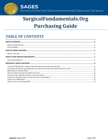
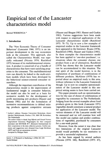
Fuseology Selection GuideFuse Selection ChecklistThe application guidelines and product data in this guideare intended to provide technical information that will helpwith application design. Since these are only a few of thecontributing parameters, application testing is stronglyrecommended and should be used to verify performance inthe circuit/application.Ambient temperature effects are in addition to thenormal re-rating, see example. Example: Given a normaloperating current of 1.5 amperes in an application usinga traditional Slo-Blo fuse at room temperature, then:Normal Operating CurrentCatalog Fuse Rating �—0.75- or 1.5 Amperes——————— 2.0 Amp Fuse (at 25ºC)0.75Many of the factors involved with fuse selection are listedbelow. For additional assistance with choosing fusesappropriate to you requirements, contact your Littelfuseproducts reprentative.Similarly, if that same fuse were operated at a very highambient temperature of 70 C, additional derating wouldbe necessary. Curve "A" (Traditional Slo-Blo Fuse) ofthat ambient temperature chart shows the maximumoperating "Percent of Rating" at 70 C to be 80%, inwhich case;Selection Factors1. Normal operating current2. Application voltage (AC or DC)3. Ambient temperatureNormal Operating CurrentCatalog Fuse Rating �—0.75 x Percent of Rating- or 1.5 Amperes——————— 2.5 Amp Fuse (at 70ºC)0.75 x 0.804. Overload current and length of time in which thefuse must open5. Maximum available fault current6. Pulses, Surge Currents, Inrush Currents, Start-upCurrents, and Circuit TransientsThis charts shows typical ambient temperature effects oncurrent carrying capacity of Littelfuse products. For specificre-rating information, please consult the product data sheetat www.littelfuse.com or contact a Littelfuse representative.7. Physical size limitations, such as length, diameter,or height8. Agency Approvals required, such as UL, CSA, VDE,METI, MITI or Military9. Fuse features (mounting type/form factor, ease ofremoval, axial leads, visual indication, etc.)10. Fuseholder features, if applicable and associatedrerating (clips, mounting block, panel mount, PCboard mount, R.F.I. shielded, etc.)11. Application testing and verification prior toproduction1. NORMAL OPERATING CURRENT: The current ratingof a fuse is typically derated 25% for operation at 25ºC toavoid nuisance blowing. For example, a fuse with a currentrating of 10A is not usually recommended for operation atmore than 7.5A in a 25ºC ambient. For additional details,see RERATING in the previous section and AMBIENTTEMPERATURE below.Curve A: Thin-Film Fuses and 313 Series (.010 to .150A)Curve B: FLAT-PAK , TeleLink , Nano2 , PICO , BladeTerminal and other leaded and catridge fusesCurve C: Resettable PTC’s2. APPLICATION VOLTAGE: The voltage rating of thefuse must be equal to, or greater than, the available circuitvoltage. For exceptions, see VOLTAGE RATING.3. AMBIENT TEMPERATURE: The current carryingcapacity tests of fuses are performed at 25ºC and will beaffected by changes in ambient temperature. The higherthe ambient temperature, the hotter the fuse will operate,and the shorter its life. Conversely, operating at a lowertemperature will prolong fuse life. A fuse also runs hotteras the normal operating current approaches or exceeds therating of the selected fuse. Practical experience indicatesfuses at room temperature should last indefinitely, ifoperated at no more than 75% of catalog fuse rating. 2014 Littelfuse Fuseology Selection Guide5www.littelfuse.com
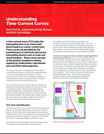
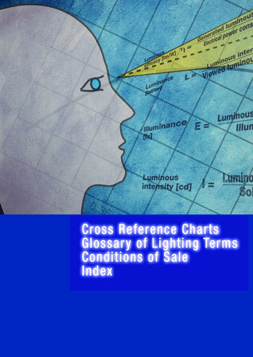
Fuseology Selection GuideFuse Selection Checklist (continued)4. OVERLOAD CURRENT CONDITION: The current levelfor which protection is required. Fault conditions may bespecified, either in terms of current or, in terms of bothcurrent and maximum time the fault can be toleratedbefore damage occurs. Time-current curves should beconsulted to try to match the fuse characteristic to thecircuit needs, while keeping in mind that the curves arebased on average data.is capable of withstanding 100,000 pulses of current (I) ofthe pulse waveform shown in Figure 1.The normal operating current is 0.75 ampere at an ambienttemperature of 25ºC.Step 1 — Refer to Chart 1 and select the appropriatepulsewaveform, which is waveform (E) in this example.Place the applicable value for peak pulse current (ip) andtime (t) into the corresponding formula for waveshape (E),and calculate the result, as shown:5. MAXIMUM FAULT CURRENT: The Interrupting Ratingof a fuse must meet or exceed the Maximum Fault Currentof the circuit.1I2t — (iP) 2t56. PULSES: The general term “pulses” is used in thiscontext to describe the broad category of wave shapesreferred to as “surge currents”, “start-up currents”, “inrushcurrents”, and “transients”. Electrical pulse conditions canvary considerably from one application to another. Differentfuse constructions may not react the same to a givenpulse condition. Electrical pulses produce thermal cyclingand possible mechanical fatigue that could affect the lifeof the fuse. Initial or start-up pulses are normal for someapplications and require the characteristic of a Slo-Blo fuse. Slo-Blo fuses incorporate a thermal delay designto enable them to survive normal start-up pulses and stillprovide protection against prolonged overloads. The startup pulse should be defined and then compared to the timecurrent curve and I2t rating for the fuse. Application testingis recommended to establish the ability of the fuse designto withstand the pulse conditions.1 — 82 .004 0.0512 A2 Sec.5This value is referred to as the “Pulse I2t”.Step 2 — Determine the required value of Nominal MeltingI2t by referring to Chart 2. A figure of 22% is shown inChart II for 100,000 occurrences of the Pulse I2t calculatedin Step 1. This Pulse I2t is converted to its required value ofNominal Melting I2t as follows:Nom. Melt I2t Pulse I2t/.220.0512/.22 0.2327 A2 Sec.Step 3 — Examine the I2t rating data for the PICO II, 125V,very fast-acting fuse. The part number 251001, 1 amperedesign is rated at 0.256 A2 Sec., which is the minimumfuse rating that will accommodate the 0.2327 A2 Sec.value calculated in Step 2. This 1 ampere fuse will alsoaccommodate the specified 0.75 ampere normal operatingcurrent, when a 25% derating factor is applied to the 1ampere rating, as previously described.Nominal melting I2t is a measure of the energy requiredto melt the fusing element and is expressed as “AmpereSquared Seconds” (A2 Sec.). This nominal melting I2t,and the energy it represents (within a time duration of8 milliseconds [0.008 second] or less and 1 millisecond[0.001 second]or less for thin film fuses), is a value that isconstant for each different fusing element. Because everyfuse type and rating, as well as its corresponding partnumber, has a different fusing element, it is necessary todetermine the I2t for each. This I2t value is a parameter ofthe fuse itself and is controlled by the element materialand the configuration of the fuse element. In additionto selecting fuses on the basis of “Normal OperatingCurrents”, “Rerating”, and “Ambient Temperature” asdiscussed earlier, it is also necessary to apply the I2tdesign approach. This nominal melting I2t is not only aconstant value for each fuse element design, but it is alsoindependent of temperature and voltage. Most often, thenominal melting I2t method of fuse selection is applied tothose applications in which the fuse must sustain largecurrent pulses of a short duration. These high-energycurrents are common in many applications and are criticalto the design analysis.7. PHYSICAL SIZE LIMITATIONS: Please refer to theproduct dimensions presented in current Littelfuse productdata sheets for specific information.8. AGENCY APPROVALS: For background informationabout common standards, please consult the STANDARDSsection of this guide or visit our Design Support web siteat www.littelfuse.com/design-support.html. For specificagency approval information for each Littelfuse product,please refer to the data sheets within this catalog andinformation presented on www.littelfuse.com. As agencyapprovals and standards may change, please rely on theinformation presented on www.littelfuse.com as currentinformation.9. FUSE FEATURES: Please consult the specific productfeatures presented within this catalog and on our website at www.littelfuse.com. For additional information andsupport contact your Littelfuse product representative.The following example should assist in providing a betterunderstanding of the application of I2t.EXAMPLE: Select a 125V, very fast-acting PICO II fuse that 2015 Littelfuse Fuseology Selection Guide6www.littelfuse.com
Fuseology Selection GuideFuse Selection Checklist (continued)FIGURE 1CHART 1WAVESHAPESAipFORMULASi kI2t ip2 ttibCurrent (Amperes)10Bip8ti ip-ktI2t (1/3)(ip2 ipib ib2) tti ip sin tI2t (1/2) ip2 t6C42l2 tPulseEnergy.001ipNormal Operating Current.002 .003 .004 .005Time (Seconds)D.006ipFigure 110. FUSEHOLDER FEATURES AND RERATING: Forinformation about the range of Littelfuse fuseholders andspecific features and characteristics, please consult witha Littelfuse products representative or visit our web site(www.littelfuse.com).EipORtFor 25ºC ambient temperatures, it is recommended thatfuseholders be operated at no more than 60% of thenominal current rating established using the controlled testconditions specified by Underwriters Laboratories. Theprimary objective of these UL test conditions is to specifycommon test standards necessary for the continuedcontrol of manufactured items intended for protectionagainst fire, etc. A copper dummy fuse is inserted inthe fuseholder by Underwriters Laboratories, and thenthe current is increased until a certain temperature riseoccurs. The majority of the heat is produced by the contactresistance of the fuseholder clips. This value of currentis considered to be the rated current of the fuseholder,expressed as 100% of rating. Some of the more common,everyday applications may differ from these UL testconditions as follows: fully enclosed fuseholders, highcontact resistance,air movement, transient spikes, andchanges in connecting cable size (diameter and length).Even small variations from the controlled test conditionscan greatly affect the ratings of the fuse-holder. Forthis reason, it is recommended that fuseholders bederated by 40% (operated at no more than 60% of thenominal current rating established using the UnderwriterLaboratories test conditions, as previously stated).Ftipt1i kt2 OR i ip(1-kt) 2I2t (1/5) ip2 ti ipe–kt)I2t (1/2) ip2 t1CHART 2PULSE CYCLE WITHSTAND CAPABILITY100,000 PulsesPulse I2t 22% of Nominal Melting I2t10,000 PulsesPulse I2t 29% of Nominal Melting I2t1,000 PulsesPulse I2t 38% of Nominal Melting I2t100 PulsesPulse I2t 48% of Nominal Melting I2t100000Number of Pulses1000011. TESTING: The factors presented here should beconsidered in selecting a fuse for a given application. Thenext step is to verify the selection by requesting samplesfor testing in the actual circuit. Before evaluating thesamples, make sure the fuse is properly mounted withgood electrical connections, using adequately sized wiresor traces. The testing should include life tests under normalconditions and overload tests Under fault conditions, toensure that the fuse will operate properly in the circuit. 2014 Littelfuse Fuseology Selection GuideI2t (1/3) ip2 tt100010010%Pulse I 2t / Average Melting I2t100%Note: Adequate time (10 seconds) must exist between pulse eventsto allow heat from the previous event to dissipate.7www.littelfuse.com
Fuseology Selection GuidePTC Characteristics and TermsOvercurrent circuit protection can be accomplishedwith the use of either a traditional fuse or PTC (positivetemperature coefficient) device.Traditional Fuses Vs. PTCsFuses and PTCs are both overcurrent protectiondevices, though each offer their own unique operatingcharacteristics and benefits. Understanding the differencesbetween the two technologies should make the choice inselection easier, depending on the application.PTCs are typically used in a wide variety of telecom,computer, consumer electronics, battery and medicalelectronics product applications where overcurrent eventsare common and automatic resettability desired.The most obvious difference is that PTCs are automaticallyresettable whereas traditional Fuses need to be replacedafter they they are tripped. Whereas a fuse will completelystop the flow of current (which may be desired in criticalapplications) after most similar overcurrent event, PTCscontinue to enable the equiment to function, except inextreme cases.Littelfuse offers PTCs with the following general forms andfeatures, and come in a variety of sizes and capacities:Surface Mount Devices: A full range of compact footprints Low hold currentBecause they reset automatically, many circuit designerschoose PTCs in instances where overcurrent events areexpected to occur often, and where maintaining lowwarranty and service costs, constant system uptime, and/or user transparency are at a premium. They are also oftenchosen in circuits that are difficult to access or in remotelocations, were fuse replacement would be difficult. Very fast trip time Low resistanceRadial Leaded Series: Protection devices up to 600Vdc A very high hold current Low trip-to-hold current ratio Low resistance.There are
FUSEOLOGY Selection Guide use F Characteristics, Terms and Consideration Factors Table of Contents Page Fuse Char