Transcription
uary 20, 2021VOLUNTARY SAFETY RECALL CAMPAIGN2013-2015 PATHFINDER; STOP LAMP SWITCH ADJUSTMENTCAMPAIGN ID #:APPLIED VEHICLES:PC7862013-2015 Pathfinder (R52)Check Service COMM or Dealer Business Systems (DBS)National Service History to confirm campaign eligibility.INTRODUCTIONNissan is conducting this voluntary safety recall campaign, on certain specific model year2013-2015 Pathfinder vehicles, to inspect and, if necessary, replace the TCC brake/stoplamp relay and adjust the stop lamp switch. This service will be performed at no charge tothe customer for parts or labor.IDENTIFICATION NUMBERNissan has assigned identification number PC786 to this campaign. This number mustappear on all communication and documentation of any nature dealing with this campaign.DEALER RESPONSIBILITYIt is the dealer’s responsibility to check Service COMM or Dealer Business Systems (DBS)National Service History for the campaign status on each vehicle falling within the range ofthis voluntary safety recall which for any reason enters the service department. Thisincludes vehicles purchased from private parties or presented by transient (tourist) ownersand vehicles in a dealer’s inventory. Federal law requires that new vehicles in dealerinventory which are the subject of a safety recall must be corrected prior to sale.Failure to do so can result in civil penalties by the National Highway Traffic SafetyAdministration. While federal law applies only to new vehicles, Nissan stronglyencourages dealers to correct any used vehicles in their inventory before they are retailed.Nissan Bulletins are intended for use by qualified technicians, not 'do-it-yourselfers'. Qualified technicians areproperly trained individuals who have the equipment, tools, safety instruction, and know-how to do a jobproperly and safely. NOTE: If you believe that a described condition may apply to a particular vehicle, DONOT assume that it does. See your Nissan dealer to determine if this applies to your vehicle.1/10
REPAIR OVERVIEW2/10NTB21-003
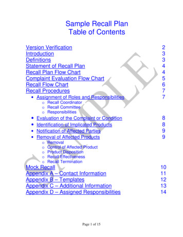
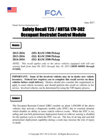
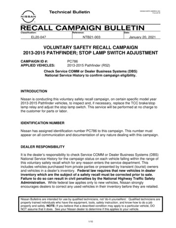
SERVICE PROCEDUREInspect for the TCC Brake/Stop Lamp Relay1.Open the hood and add fender protection (Figure 1).2.Locate the under hood fuse and relay box.HINT: The under hood fuse and relay box is found under the passenger side cowlarea.Under Hood Fuseand Relay BoxFigure 1Figure 23/10NTB21-003
3.Remove the cover of the under hoodfuse and relay box.Fuse and RelayBox CoverHINT: Pull outward on the side latchesto remove the cover.Figure 34.Locate the TCC brake/stop lamp relay. If the TCC brake/stop lamp relay ispresent, continue to step 5 onpage 5. If the TCC brake/stop lamp relay isnot present, no repair is required. Reassemble the vehicle in thereverse order of removal andreview the CLAIMSINFORMATION on page 10.4/10TCC Brake/StopLamp RelayFigure 4NTB21-003
Replace TCC Brake/Stop Lamp Relay5.Remove the TCC brake/stop lamprelay and discard (it will not bereused).HINT: To release the relay, use asmall, flat screw driver to push therelay latch inward (toward the relay)while gently pulling the relay outward.Figure 56.Install the new TCC brake/stop lamprelay listed in PARTS INFORMATIONon page 10.HINT: A click noise should be heardwhen the relay is fully seated.TCC Brake/StopLamp RelayFigure 67.Install the fuse and relay box cover.Fuse and RelayCoverFigure 75/10NTB21-003
8.Remove the fender protection andclose the hood.Figure 8Swap the Stop Lamp Switch and Brake Pedal Position Switch Locations9.Open the driver side door and movethe driver’s seat to the full rearwardposition.Figure 910.Look under the driver side lower dasharea to locate the stop lamp switchand the brake pedal position switch.HINT: Use a portable light source toilluminate the area. Both switches areto the right of the brake pedal.Look up HEREFigure 106/10NTB21-003
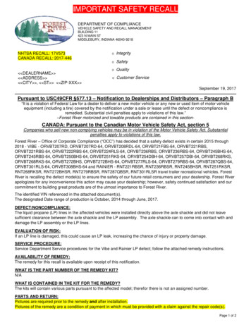
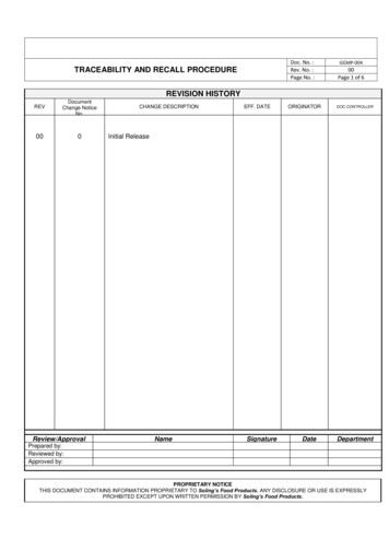
11.Swap the positions of the stop lampswitch and the brake pedal positionswitch.Stop LampSwitchIMPORTANT: The stop lamp switch(white connector) must be in theupper position (Figure 11). Be sure to check the switchpositions before swapping. Somevehicles may already have the stoplamp switch in the upper positionand will not require the switchpositions to be swapped.Brake PedalPosition SwitchFigure 11HINT: The stop lamp switch has awhite connector with yellow and whitewires. The brake pedal position switchhas a tan connector with red and lightgreen wires. There is no need to remove the harness connector from either of the switches. Turn the switches 45 counterclockwise to remove. To reinstall, insert the threaded end of the switches into the brake pedal bracket,and then turn the switches 45 clockwise to lock in place.7/10NTB21-003
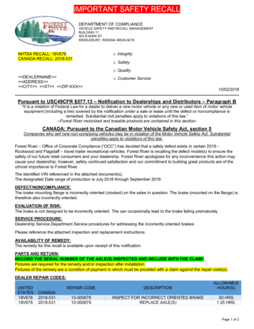
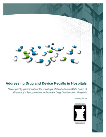
Adjust Both Switches12.Adjust both the stop lamp switch and the brake pedal position switch using theprocedure and specifications provided in the ESM. For stop lamp switch and brake pedal position switch adjustment, refer to the ESMsection: F: BRAKES BR – Brake System BASIC INSPECTION BRAKEPEDAL Inspection STOP LAMP SWITCH AND BRAKE PEDAL POSITIONSWITCH.IMPORTANT: Make sure that the clearance (A) between the brake pedal bracket (3)and the brake pedal position and stop lamp switch (1 & 2) contact ends are withinspecification. The stop lamps must turn OFF when the brake pedal is released. Clearance (A): 0.74 – 1.96 mm (0.0291 – 0.0772 in.)Figure 12Completed Repair Validation Checks13.Verify the stop lamps operate properly.NOTE: If the stop lamps do notoperate properly, perform step 12 toreadjust the switches.IMPORTANT: The stop lamps mustturn OFF when the brake pedal isreleased.Figure 138/10NTB21-003
14.Verify the automatic speed control device (ASCD) operates correctly.NOTE: If the ASCD does not operate correctly, perform step 12 to readjust theswitches.15.Verify no DTCs related to the stop lamp switch or brake pedal position switchadjustments are stored.NOTE: If DTCs related to the switch adjustments are present, perform step 12 toreadjust the switches.9/10NTB21-003
PARTS INFORMATIONDESCRIPTIONPART NUMBERRelay25230-79917QUANTITY1(If Needed)CLAIMS INFORMATIONSubmit a “CM” line claim using the following claims coding:CAMPAIGN (“CM”) IDPC786DESCRIPTIONInspect for TCC Brake/Stop Lamp Relay(OK Condition, No Relay Present)Inspect and Replace TCC Brake/StopLamp Relay, Swap Stop Lamp Switchand Brake Pedal Position SwitchPositionsOP CODEFRTPC78600.2 hrPC78610.4 hrAMENDMENT HISTORYPUBLISHED DATE REFERENCEJanuary 20, 2021NTB21-003DESCRIPTIONOriginal bulletin published10/10NTB21-003
Open the hood and add fender protection (Figure 1). 2. Locate the under hood fuse and relay box. HINT: The under hood fuse and relay box is found under the passenger side cowl area. Figure 1 Figure 2 Under Hood Fuse and Relay Box . 4/10 NTB21-00