Transcription
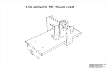
3 Axis CNC Machine - MDF Plans and Cut ListCopyright 2008 Patrick Hood-Daniel - Theuser of these plans assumes allresponsibility for his or her actions duringthe process of using these plans.
11"2'-5167"3'-6164'-4"Overall Dimensions and General Notes:These measurements include only the MDF components and not other external components such as motors, bearings, leadscrews, etc.For placement of various items such as motors, lead screws, bearings and other unique hardare items, go to thebuildyourcnc.com website.Notes: All screw diameters and types will be 41" - 20 unless specified otherwise. Hole dimeters and dimensions are seldomlyrepeated for simplicity. If there is an inquiry to a hole size, or a position, refer to another part of the drawing. Any omissionsand errors should be relayed to Patrick Hood-Daniel (713-952-7511) or phooddaniel@buildyourcnc.com.2'-038"If there is any concern with you having solde responsibility for any actions resulting from this plans, please return the kit and Iwill refund your purchase in whole within 30 days of purchase.4'-4"
Z Axis BearingSupportsThere are two of these pieceson the machine. They serve assupports for the linear bearingsand for the router mount.Each piece is an exact mirror ofthe other.Hardware Needed:4 2" screws to connect to thez-back support and the routermount base.434" screws to secure the linearbearing angle.
Router BaseThis piece will be used dually asthe router base and as a dustcollector top.There is only one of these pieceson the machine.The diameter for the large holefor the vacuum hose should bemodified to fit your vacuum hose.The medium hole is used for therouter collet to protrude.Router mounting holes will needto be marked and bored so thatyour router can be utilized. Theunderside of this base shouldhave these holes countersunk soas not to reveal the screw headsas this may interfere with thematerial to be cut.The four remaining holes is toreceive a cross dowels to connectto the screws from the Z AxisBearing Supports.
Z Axis Rail SupportThis piece will be used as thesupport for the aluminum anglesas rails. The sides are chamferedat 45 degree angles with a smallportion of the MDF remaining forthe router bearing quide.7The 4 holes at 16" are used toreceive cross dowels to connectto the y-axis bearing supports.
Motor MountThese pieces will enable you tomount the motors to drive thelinear motion.Countersunk holes will need toreceive the #10 nuts. Use themethod that is exhibited on thebuildyourcnc.com website to drivethe nuts into these holes.The two outside holes are toreceive 3" screws in order toconnect through the the main 34"piece being attached, and twomotor mounts.The large center hole is simply toallow space for the couplings andif the bearing is not flush againstthe main piece.There are six of these piecesonthe machine.
Y Axis LinearBearing SupportsThere are two of these pieces inthe machine and they serve aslinear bearing supports and toconnect to the Z rail support andthe Z back supports.You will need four 34" screws toattach the bearing angle (the fourholes in the middle. Four 2"screws are needed for the fouroutside holes to connect to they-axis back support and the z-axisrail support pieces.The two holes outside of thelarger bearing hole is used tofasten the motor mount using 3"screws.
Z Axis BackSupportsThe piece shown at the top is thez-axis back support piece that willalso serve to hold the z-nut. Thepiece at the bottom servessimpley as extra support for therouter sides. Both will have acenter bore on each end to mountto the router sides (shown upperright).You will need four cross dowels,two for each piece.For the piece shown at the top,two 1-1/2" screws and nuts arerequired to fasten thetransmission nut.
Y Axis BackSupportsThese two pieces are similar tothe z-axis back support found onthe previous page. These pieceswill serve as the back support forthe y-axis and one (top) will holdthe y-nut.You will need four cross dowels,two for each.For the piece show at the top, two1-1/2" screws and nuts arerequired to fasten thetransmission nut.
Scale: 1:2Gantry SideThe Gantry sides serve to hold upthe y and z axes and ride on thex-axis rails.The five holes lined up on the leftwill connect to the y-axis railsuport piece using 2" screws.The six holes in a gridconfiguration are used to attachthe bearing angle using 34" screws.The three holes to the far right willconnect to the gantry bottompiece and will require three 2"screws.The large holes is for the bearingand needs to be countersunk tothe bearing thickness. The twoadjacent holes will hold the motormount and will require the use of3" screws.There are two of the gantry sidesin the machine each mirroring theother.
Scale: 1:2X Table EndThere are two of these table endson the machine, each an exactmirror of the other.You will need six 2" screws tofasten this to the two table halves.The two holes on either side ofthe bearing seat require 3" screwsto fasten the motor mounts.
Scale: 5/16" 1"Y Axis Rail SupportFront ReinforcementThis is the back part of the y-axisrail support piece.These will fasten with the 1"screws mentioned on the previouspage.Y Axis Rail SupportFrontThe is the main gantry supportand the piece that supports therails for the y-axis travel.You will need 7 cross dowels oneach side, two of which will beused to fasten the rail to thepiece. The other will be used toattach the gantry sides.The 10 holes in the center will beused to fasten the reinforcementwith 38" countersinking (half waythrough the 34" board) to allow 1"screws to be used. There shouldbe very little protrusion of thescrew head or the nut so thez-axis assembly will not haveobstruction.
Scale: 5/16" 1"Gantry BottomSupportThis is the piece that will serve asthe support to maintain alignmentand strength for the gantry aroundthe table rails.Six cross dowels will be used toconnect to the gantry sides andtwo 3" screws are needed tofasten the x-nut piece.Scale: 1:1Gantry Bottom X-nutSupportThis piece will fasten to the gantrybottom from the previous page.Two 1 -21" screws are neede tosecure the transmission nut to thepiece, and two 3" screws to fastento the gantry bottom.
Scale: 1:4Bottom Half of TableThis is the bottom half of thecomplete table assmebly.The piece is chamfered to receivetwo 1-1/4" angles for linear motionof the gantry.The six holes in the middle are tobe used to fasten the two halvesof the table together.The five holes on either end willreceive cross dowels. Three forconnecting to the table ends andtwo for holding the angles inplace.The two holes for the angleattachment should be drilled onlyafter the two halves are preparedand fastened together.4'1" for the table length may seemnon-typical; however, this is thenominal dimension of stock foundat the local home improvementstore.
Scale: 1:4Top Half of TableThe top half of the table will serveas the cutting surface. The holesin the middle are countersunk sothere is not protrusion of screwheads to interfere with thematerial to be cut.Six 1-1/2" screws are needed forthe middle holes to fasten theother table half.
on the machine. They serve as supports for the linear bearings and for the router mount. Each piece is an exact mirror of the other. Hardware Needed: 4 2" screws to connect to the z-back support and the router mount base. 43 4" screws to