Transcription
Quick Start GuideCisco 2800 Series Integrated Services Routers Quick Start GuideINCLUDING LICENSE AND WARRANTY1Cisco 90-Day Limited Hardware Warranty Terms2Overview3Documents, Equipment, and Tools4Install Chassis5Connect Cables6Power Up the Router7Interface Numbering8Perform Initial Configuration9Where to Go Next10 Obtaining Documentation11 Documentation Feedback12 Cisco Product Security Overview13 Obtaining Technical Assistance14 Obtaining Additional Publications and Information
Revised: October 11, 2005, 78-16015-071 Cisco 90-Day Limited Hardware Warranty TermsThere are special terms applicable to your hardware warranty and various services that you can use during the warranty period.Your formal Warranty Statement, including the warranties and license agreements applicable to Cisco software, is available onCisco.com. Follow these steps to access and download the Cisco Information Packet and your warranty and license agreementsfrom Cisco.com.1. Launch your browser, and go to this URL:http://www.cisco.com/univercd/cc/td/doc/es inpck/cetrans.htmThe Warranties and License Agreements page appears.2. To read the Cisco Information Packet, follow these steps:a. Click the Information Packet Number field, and make sure that the part number 78-5235-03A0 is highlighted.b. Select the language in which you would like to read the document.c. Click Go.The Cisco Limited Warranty and Software License page from the Information Packet appears.d. Read the document online, or click the PDF icon to download and print the document in Adobe Portable DocumentFormat (PDF).NoteYou must have Adobe Acrobat Reader to view and print PDF files. You can download the reader from Adobe’swebsite, http://www.adobe.com.3. To read translated and localized warranty information about your product, follow these steps:a. Enter this part number in the Warranty Document Number field:78-5236-01C0b. Select the language in which you would like to read the document.c. Click Go.The Cisco warranty page appears.d. Review the document online, or click the PDF icon to download and print the document in Adobe Portable DocumentFormat (PDF).You can also contact the Cisco service and support website for assistance:http://www.cisco.com/public/Support root.shtmlDuration of Hardware WarrantyNinety (90) days.Replacement, Repair, or Refund Policy for HardwareCisco or its service center will use commercially reasonable efforts to ship a replacement part within ten (10) working days afterreceipt of a Return Materials Authorization (RMA) request. Actual delivery times can vary, depending on the customer location.Cisco reserves the right to refund the purchase price as its exclusive warranty remedy.2
To Receive a Return Materials Authorization (RMA) NumberContact the company from whom you purchased the product. If you purchased the product directly from Cisco, contact yourCisco Sales and Service Representative.Complete the information below, and keep it for reference:Company product purchased fromCompany telephone numberProduct model numberProduct serial numberMaintenance contract number2 OverviewThe Cisco 2800 series integrated services routers include the Cisco 2801, Cisco 2811, Cisco 2821, and Cisco 2851 routers.These routers differ as follows: Cisco 2801 routers support 2 HWIC/WIC/VIC/VWIC slots capable of supporting double-wide HWICs, 1 WIC/VWIC/VICslot, 1 VWIC/VIC (voice only) slot, 2 advanced integration modules (AIM), 2 packet voice data modules (PVDMs), 2 FastEthernet connections, and 16 ports of IP phone power output. Cisco 2811 routers support 1 single network module enhanced (NME), 4 single or 2 double high-speed WAN interface cards(HWICs), 2 AIMs, 2 packet voice data modules (PVDMs), 2 Fast Ethernet connections, and 24 ports of IP phone poweroutput. In Cisco 2821 routers, the network module slot adds support for a single network module enhanced extended (NME-X),and an additional slot supports an extension voice module (EVM); 3 PVDMs are supported; the LAN ports support 2Gigabit Ethernet ports; and 36 ports of IP phone power output are available. In Cisco 2851 routers, the network module slot adds support for network module double-wide (NMDs) and networkmodule enhanced extended double-wide (NME-XDs), and the IP phone power output is increased to 48 ports.NoteA high density extension module (HDEM) operates in the EVM slot on the Cisco 2821 and Cisco 2851 routers.The EVM slot supports additional voice services and density without consuming the network module slot on thoserouters.This document provides the minimum necessary information to help you install the router, power it up, and configure a networkconnection. This document directs you to other documents for the following information: More detailed router installation instructions, descriptions, and specifications Procedures for installing modules, interface cards, power supplies, and memoryNoteThe interface numbering on Cisco 2800 series routers is different from the numbering on Cisco 2600 series routers.For more information on interface numbering, see the “Interface Numbering” section on page 30. Software configuration Regulatory compliance and safety information3
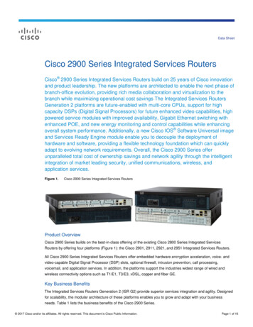
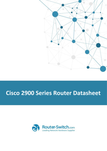
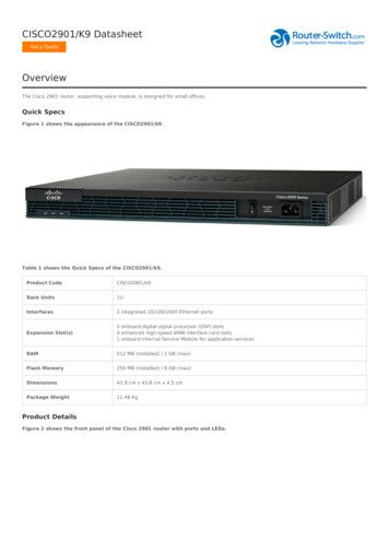
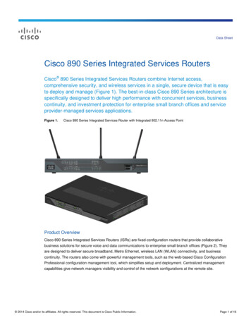
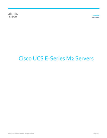
Product Serial Number LocationYou may need your product serial number when calling the Technical Assistance Center (TAC).Figure 1 shows the serial number location for the Cisco 2801 router. The label is located on the rear of the chassis, at the bottomedge, near the lower left corner.Serial Number Label Location for Cisco 2801 Router117342 781-00286-01Figure 1SN: AAANNNNXXXXSN: AAANNNNXXXXFigure 2 shows the serial number location for the Cisco 2811 router. The label is located on the rear of the chassis, near the topright corner, to the left of the CLEI label.Figure 2Serial Number Label Location for Cisco 2811 RouterSLOT1SLOT2AFA ACTS SPEEDFE 0/1A FDXA LINKFE 0/0103962 781-00287-01SLOT3ENM0AS SLO LT0FSLPVDM1PVDM0AIM1AIM0SN: AAANNNNXXXXFigure 3 shows the serial number location for the Cisco 2821 router and the Cisco 2851 router. The label is located on the rearof the chassis, near the top right corner, below the CLEI label.Figure 3A ACTS SPEEDFE 0/1AFSerial Number Label Location for Cisco 2821 Router and Cisco 2851 RouterA FDXA LINKFE 0/0ASFLSLPVDM1PVDM0AIM1AIM0SN: AAANNNNXXXXSN: AAANNNNXXXX4103963 781-00288-01PVDM2
Cisco Product Identification ToolThe Cisco Product Identification (CPI) tool provides detailed illustrations and descriptions showing where to find serial numberlabels on Cisco products. It includes the following features: A search option that allows browsing for models using a tree-structured product hierarchy A search field on the final results page making it easier to look up multiple products Clear identification of end-of-sale products in results listsThe tool streamlines the process of locating serial number labels and identifying products. Serial number information expeditesthe entitlement process and is important for access to support services.The Cisco Product Identification tool can be accessed at the following URL:http://tools.cisco.com/Support/CPI/index.do3 Documents, Equipment, and ToolsUser DocumentationFor complete platform documentation, see the following t/access/acs mod/2800/index.htmAll the documents referenced in this quick start guide are available on Cisco.com. See the “Where to Go Next” section onpage 36. To view or print an online document in its original page format, click the PDF icon.Translated oduct/access/acs d/cc/td/doc/product/access/acs mod/2800/qsg/index.htmItems Included with Cisco 2801 RoutersYour router package should include the following items in addition to the router: One blue RJ-45-to-DB-9 console cable; one DB-9-to-DB-25 modem adapter Power cord Cisco.com card; Cisco product registration card 19-inch (48.26-cm) rack-mount brackets with bracket screws Cable management bracket with one mounting screw Rubber chassis feet for desktop application Cisco 2800 Series and Cisco 3800 Series Regulatory Compliance and Safety Information document Cisco Router and Security Device Manager (SDM) Quick Start Guide document Cisco 2800 Series Integrated Services Routers Quick Start Guide (this document)5
Items Included with Cisco 2811, Cisco 2821, and Cisco 2851 RoutersYour router package should include the following items in addition to the router: RJ-45-to-DB-9 console cable and RJ-45-to-DB-25 modem cable for management access Ground lug; AC power cord with AC-powered routers Cisco product registration card; Cisco.com card One pair of rack-mount brackets with screws for 19-inch racks Cable management bracket; optional 23-inch rack mount brackets, if ordered Ethernet cable for LAN interface Cisco 2800 Series and Cisco 3800 Series Regulatory Compliance and Safety Information document Cisco Router and Security Device Manager (SDM) Quick Start Guide document Cisco 2800 Series Integrated Services Routers Quick Start Guide (this document)Items Not IncludedIndividual items in this list may be required for your installation: PC running terminal emulation software, or a modem for remote administrative access Cables for WAN interfaces, voice interfaces, additional LAN interfaces, or USB interface Cable ties, number 2 Phillips screwdriver Four screws for installing the router in a rack Other typical equipment, such as channel service unit/data service unit (CSU/DSU); NT1 device for ISDN-BRI S/T; Ethernethub; USB devicesNoteThe onboard USB 1.1 ports support only Cisco-approved and qualified USB devices.4 Install ChassisThis section contains basic installation procedures. For more detailed installation instructions, see the Cisco 2800 serieshardware installation documentation at the following t/access/acs mod/2800/hw/index.htmSafety InformationThe Cisco 2800 and Cisco 3800 Series Integrated Services Routers Regulatory Compliance and Safety Information documentcontains translations of the warnings that appear in this quick start guide.For safety information you must know before working on your Cisco router, see the Cisco 2800 and Cisco 3800 SeriesIntegrated Services Routers Regulatory Compliance and Safety Information document that accompanied this device.6
Warning DefinitionWarningIMPORTANT SAFETY INSTRUCTIONSThis warning symbol means danger. You are in a situation that could cause bodily injury. Before youwork on any equipment, be aware of the hazards involved with electrical circuitry and be familiar withstandard practices for preventing accidents. Use the statement number provided at the end of eachwarning to locate its translation in the translated safety warnings that accompanied this device.Statement 1071SAVE THESE INSTRUCTIONSWaarschuwingBELANGRIJKE VEILIGHEIDSINSTRUCTIESDit waarschuwingssymbool betekent gevaar. U verkeert in een situatie die lichamelijk letsel kanveroorzaken. Voordat u aan enige apparatuur gaat werken, dient u zich bewust te zijn van de bijelektrische schakelingen betrokken risico's en dient u op de hoogte te zijn van de standaard praktijkenom ongelukken te voorkomen. Voor een vertaling van de waarschuwingen die in deze publicatieverschijnen, dient u de vertaalde veiligheidswaarschuwingen te raadplegen die bij dit apparaatworden geleverd.Opmerking BEWAAR DEZE INSTRUCTIES.VaroitusTÄRKEITÄ TURVALLISUUTEEN LIITTYVIÄ OHJEITATämä varoitusmerkki merkitsee vaaraa. Olet tilanteessa, joka voi johtaa ruumiinvammaan. Ennen kuintyöskentelet minkään laitteiston parissa, ota selvää sähkökytkentöihin liittyvistä vaaroista jatavanomaisista onnettomuuksien ehkäisykeinoista. Tässä asiakirjassa esitettyjen varoitustenkäännökset löydät laitteen mukana toimitetuista ohjeista.Huomautus SÄILYTÄ NÄMÄ OHJEETAttentionIMPORTANTES INFORMATIONS DE SÉCURITÉCe symbole d'avertissement indique un danger. Vous vous trouvez dans une situation pouvant causerdes blessures ou des dommages corporels. Avant de travailler sur un équipement, soyez conscient desdangers posés par les circuits électriques et familiarisez-vous avec les procédures courammentutilisées pour éviter les accidents. Pour prendre connaissance des traductions d'avertissementsfigurant dans cette publication, consultez les consignes de sécurité traduites qui accompagnent cetappareil.Remarque CONSERVEZ CES INFORMATIONSWarnungWICHTIGE SICHERHEITSANWEISUNGENDieses Warnsymbol bedeutet Gefahr. Sie befinden sich in einer Situation, die zu einer Körperverletzungführen könnte. Bevor Sie mit der Arbeit an irgendeinem Gerät beginnen, seien Sie sich der mitelektrischen Stromkreisen verbundenen Gefahren und der Standardpraktiken zur Vermeidung vonUnfällen bewusst. Übersetzungen der in dieser Veröffentlichung enthaltenen Warnhinweise sind imLieferumfang des Geräts enthalten.Hinweis BEWAHREN SIE DIESE SICHERHEITSANWEISUNGEN AUF7
AvvertenzaIMPORTANTI ISTRUZIONI SULLA SICUREZZAQuesto simbolo di avvertenza indica un pericolo. La situazione potrebbe causare infortuni allepersone. Prima di intervenire su qualsiasi apparecchiatura, occorre essere al corrente dei pericolirelativi ai circuiti elettrici e conoscere le procedure standard per la prevenzione di incidenti. Per letraduzioni delle avvertenze riportate in questo documento, vedere le avvertenze di sicurezza cheaccompagnano questo dispositivo.Nota CONSERVARE QUESTE ISTRUZIONIAdvarselVIKTIGE SIKKERHETSINSTRUKSJONERDette varselssymbolet betyr fare. Du befinner deg i en situasjon som kan forårsake personskade. Førdu utfører arbeid med utstyret, bør du være oppmerksom på farene som er forbundet med elektriskekretssystemer, og du bør være kjent med vanlig praksis for å unngå ulykker. For å se oversettelser avadvarslene i denne publikasjonen, se de oversatte sikkerhetsvarslene som følger med denne enheten.Merk TA VARE PÅ DISSE INSTRUKSJONENEAvisoINSTRUÇÕES IMPORTANTES DE SEGURANÇAEste símbolo de aviso significa perigo. O utilizador encontra-se numa situação que poderá sercausadora de lesões corporais. Antes de iniciar a utilização de qualquer equipamento, tenha ematenção os perigos envolvidos no manuseamento de circuitos eléctricos e familiarize-se com aspráticas habituais de prevenção de acidentes. Para ver traduções dos avisos incluídos nestapublicação, consulte os avisos de segurança traduzidos que acompanham este dispositivo.Nota GUARDE ESTAS INSTRUÇÕES¡Advertencia!INSTRUCCIONES IMPORTANTES DE SEGURIDADEste símbolo de aviso indica peligro. Existe riesgo para su integridad física. Antes de manipularcualquier equipo, considere los riesgos de la corriente eléctrica y familiarícese con losprocedimientos estándar de prevención de accidentes. Vea las traducciones de las advertencias queacompañan a este dispositivo.Nota GUARDE ESTAS INSTRUCCIONESVarning!VIKTIGA SÄKERHETSANVISNINGARDenna varningssignal signalerar fara. Du befinner dig i en situation som kan leda till personskada.Innan du utför arbete på någon utrustning måste du vara medveten om farorna med elkretsar och kännatill vanliga förfaranden för att förebygga olyckor. Se översättningarna av de varningsmeddelanden somfinns i denna publikation, och se de översatta säkerhetsvarningarna som medföljer denna anordning.OBS! SPARA DESSA ANVISNINGAR8
AvisoINSTRUÇÕES IMPORTANTES DE SEGURANÇAEste símbolo de aviso significa perigo. Você se encontra em uma situação em que há risco de lesõescorporais. Antes de trabalhar com qualquer equipamento, esteja ciente dos riscos que envolvem oscircuitos elétricos e familiarize-se com as práticas padrão de prevenção de acidentes. Use o númeroda declaração fornecido ao final de cada aviso para localizar sua tradução nos avisos de segurançatraduzidos que acompanham o dispositivo.GUARDE ESTAS INSTRUÇÕES9
AdvarselVIGTIGE SIKKERHEDSANVISNINGERDette advarselssymbol betyder fare. Du befinder dig i en situation med risiko for legemesbeskadigelse.Før du begynder arbejde på udstyr, skal du være opmærksom på de involverede risici, der er vedelektriske kredsløb, og du skal sætte dig ind i standardprocedurer til undgåelse af ulykker. Brugerklæringsnummeret efter hver advarsel for at finde oversættelsen i de oversatte advarsler, der fulgtemed denne enhed.GEM DISSE ANVISNINGER10
WarningBefore working on a system that has an on/off switch, turn OFF the power and unplug the power cord. Statement 1WarningRead the installation instructions before connecting the system to the power source. Statement 1004WarningThis unit is intended for installation in restricted access areas. A restricted access area can be accessed onlythrough the use of a special tool, lock and key, or other means of security. Statement 1017WarningBlank faceplates and cover panels serve three important functions: they prevent exposure to hazardous voltagesand currents inside the chassis; they contain electromagnetic interference (EMI) that might disrupt otherequipment; and they direct the flow of cooling air through the chassis. Do not operate the system unless all cards,faceplates, front covers, and rear covers are in place. Statement 102911
WarningOnly trained and qualified personnel should be allowed to install, replace, or service this equipment.Statement 1030WarningTo prevent personal injury or damage to the chassis, never attempt to lift or tilt the chassis using the handles onmodules (such as power supplies, fans, or cards); these types of handles are not designed to support the weightof the unit. Statement 1032WarningThis equipment must be installed and maintained by service personnel as defined by AS/NZS 3260. Incorrectlyconnecting this equipment to a general-purpose outlet could be hazardous. The telecommunications lines must bedisconnected 1) before unplugging the main power connector or 2) while the housing is open, or both.Statement 1043WarningUltimate disposal of this product should be handled according to all national laws and regulations. Statement 1040WarningTo prevent the system from overheating, do not operate it in an area that exceeds the maximum recommendedambient temperature of 40 deg. Statement 1047Installing the RouterNoteCisco 2800 series routers are normally ordered with modules and interface cards. Before you remove or install anymodules or interface cards, see the documents that accompany those items or to the online Cisco 2800 series hardwareinstallation documentation at the following t/access/acs mod/2800/hw/index.htmFor module and interface card compatibility information, see the data sheet for each module and interface card.WarningBefore working on a system that has an on/off switch, turn OFF the power and unplug the power cord. Statement 1You can set any Cisco 2800 series router on a desktop or install it in a rack. A Cisco 2811 router can also be mounted on a wallor other flat surface. See the applicable instructions in the following sections. Rack-Mounting the Router, page 12 Wall-Mounting the Router—Cisco 2811 Routers Only, page 16 Installing the Router on a Desktop, page 17CautionTo prevent damage to the chassis, never attempt to lift or tilt the chassis by the plastic panel on the front. Alwayshold the chassis by the metal body.Rack-Mounting the RouterCisco 2811, Cisco 2821, and Cisco 2851 routers can be installed in 19- and 23-inch (48.26-cm and 58.42-cm) racks. Cisco 2801routers can be installed only in 19-inch racks, and cannot be center mounted. Use the standard brackets for mounting the chassisin a 19-inch rack; use the optional larger brackets for mounting the chassis in a 23-inch rack.12
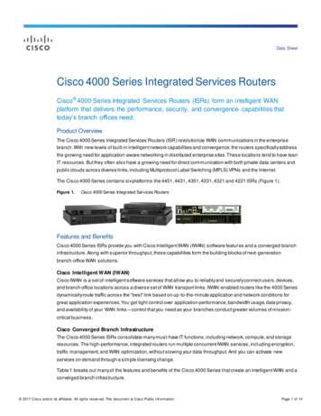
You can mount the router in the following ways: Center mounting—Brackets attached in the center of the chassis with only the front panel facing forward Front mounting—Brackets attached at the front of the chassis with the front panel facing forward Rear mounting—Brackets attached at the rear of the chassis with the rear panel facing forwardThe brackets are shown in Figure 4, Figure 5, and Figure 6.Brackets for Rack-Mounting of Cisco 2801 RoutersFigure 5Brackets for Rack-Mounting of Cisco 2811 Routers95769Figure 4Bracket pair for 23-inch rack95785Bracket pair for 19-inch rackFigure 6Brackets for Rack-Mounting of Cisco 2821 and Cisco 2851 RoutersBracket pair for 23-inch rack95744Bracket pair for 19-inch rackAttaching Brackets to the Router for Rack-MountingAttach the mounting brackets to the router chassis as shown in Figure 7 through Figure 9, using the screws provided.CautionDo not overtorque the screws. The recommended torque is 15–18 in-lb (1.7–2.0 N-m).Attach the second bracket to the opposite side of the chassis. Use a number 2 Phillips screwdriver to install the bracket screws.CautionYour chassis installation must allow unrestricted airflow for chassis cooling.13
Figure 7Bracket Installation for Front MountingSYS AUX/PWR PWR SYSACTCFCOMPACTFLASHDo Not Remove PUT18A100-240V 3A50/60 HzBracketfor 23-inch rackBracketfor 19-inch rackUse four screws on each side.Figure 895745Bracketfor 19-inch rackBracketfor 23-inch rackBracket Installation for Rear MountingA ACTS SPEEDFE 0/1AFA FDXA LINKFE 0/0ASFLSPVDM2LPVDM1PVDM0AIM1AIM0Bracketfor 23-inch rackBracketfor 19-inch rackUse four screws on each side.Bracket Installation for Center Mounting with Front Panel ForwardSYS AUX/PWR PWR SYSACTCFCOMPACTFLASHDo Not Remove DuringOPTIONALRPS12VBracketfor 23-inch rackNetworkCONSOLE10OperationAUXINPUT18A100-240V 3A50/60 HzBracketfor 19-inch rackUse four screws on each side.14Bracketfor 23-inch rackBracketfor 19-inch rackBracketfor 23-inch rack95746Figure 995747Bracketfor 19-inch rack
Installing the Router in a RackWarningTo prevent bodily injury when mounting or servicing this unit in a rack, you must take special precautions toensure that the system remains stable. The following guidelines are provided to ensure your safety: This unit should be mounted at the bottom of the rack if it is the only unit in the rack. When mounting this unit in a partially filled rack, load the rack from the bottom to the top with the heaviest componentat the bottom of the rack. If the rack is provided with stabilizing devices, install the stabilizers before mounting or servicing the unit in the rack.Statement 1006CautionBe sure to leave space above and below each router in a rack to allow for cooling air circulation.Use two screws for each side (supplied with the rack, not with the router). Suggestion: Start the lower pair of screws first, andrest the brackets on the lower screws while you insert the upper pair of screws.TipThe screw slots in the brackets are spaced to line up with every second pair of screw holes in the rack. When the correctscrew holes are used, the small threaded holes in the brackets line up with unused screw holes in the rack. If the smallholes do not line up with the rack holes, you must raise or lower the brackets to the next rack hole.Attaching the Cable Management BracketThe cable management bracket provides attachment points for organizing and routing cables. Attach the cable managementbracket to the left or right rack-mount bracket using the screw provided. On rack-mount brackets for Cisco 2821 andCisco 2851 routers, you can attach the cable management bracket to either the upper or the lower threaded hole. See Figure 10and Figure 11 for cable management bracket attachment locations.Attaching the Cable Management Bracket to the Cisco 2801 Router95772Figure 10Cable management screw15
Figure 11Attaching the Cable Management Bracket to the Cisco 2811 RouterSLOT3SLOT1SLOT2AFA ACTS SPEEDFE 0/1A FDXA LINKFE 0/0AS SLO LT095947ENM0FSLPVDM1PVDM0AIM1AIM0Cable management bracket.Either edge may go up. Attachto either side of the chassis.Wall-Mounting the Router—Cisco 2811 Routers OnlyYou can mount a Cisco 2811 router on a wall. Cisco 2801, Cisco 2821, and Cisco 2851 routers are not designed forwall-mounting.WarningThis unit is intended to be mounted on a wall. Please read the wall mounting instructions carefully beforebeginning installation. Failure to use the correct hardware or to follow the correct procedures could result in ahazardous situation to people and damage to the system. Statement 248To attach a Cisco 2811 router to a wall or other vertical surface, use the 23-inch (58.42-cm) rack-mount brackets to attach therouter to the wall as described in the following sections.Attaching Brackets to the Router for Wall MountingAttach the standard brackets to the chassis as shown in Figure 12, using the four screws provided for each bracket.Figure 12CFCOMPACT1FLASHDo Not Remove During NetworkCONSOLE0OperationAUX103708SYS AUX/PWR PWR SYSACTAttaching the Brackets for Wall-Mounting a Cisco 2811 RouterOPTIONALRPS INPUTWARNING-- RPS covermustequipment be installed whenand an RPSis wall-mounteis not conn dected12V11A-48V4A100-240V 4A50/60 HzScrews fromaccessory kitAttaching the Router to a WallAttach the router to the wall using the brackets previously attached and attachment hardware that you provide as follows: For attaching to a wall stud, each bracket requires two #10 wood screws (round- or pan-head) with #10 washers, or two#10 washer-head screws. The screws must be long enough to penetrate at least 3/4 inch (20 mm) into supporting wood orinto a metal wall stud. For hollow-wall mounting, each bracket requires two wall anchors with washers. Wall anchors and washers must be sizeNo. 10.16
CautionThe router must be mounted with the power connections oriented downward. Failure to do so could present a firehazard.Installing the Router on a DesktopIf you install your Cisco 2800 series router on a desktop, observe the following precautions:NoteFor Cisco 2801 routers, attach the four rubber feet to the bottom of the chassis.CautionYour chassis installation must allow unrestricted airflow for chassis cooling. For placing the router on a desktop,keep at least 1 inch (2.54 cm) of clear space beside the cooling inlet and exhaust vents.CautionDo not place any items that weigh more than 10 pounds (4.5 kilograms) on top of the chassis, and do not stackrouters on a desktop.Grounding the ChassisWarningThis equipment must be grounded. Never defeat the ground conductor or operate the equipment in the absence ofa suitably installed ground conductor. Contact the appropriate electrical inspection authority or an electrician ifyou are uncertain that suitable grounding is available. Statement 1024WarningDuring this procedure, wear grounding wrist straps to avoid ESD damage to the card. Do not directly touch thebackplane with your hand or any metal tool, or you could shock yourself. Statement 94You must connect the chassis to a reliable earth ground; the ground wire must be installed in accordance with local electricalsafety standards. For NEBS-compliant grounding, use size 6 AWG (13 mm2) copper wire and the ground lug provided in the accessory kit. For NEC-compliant grounding, use size 14 AWG (2 mm2) or larger copper wire and an appropriate user-supplied ringterminal with an inner diameter of 1/4 in. (5-7 mm). For EN/IEC 60950-compliant grounding, use size 18 AWG (1 mm2) or larger copper wire and an appropriate user-suppliedring terminal.WarningThis equipment needs to be grounded. Use a green and yellow 14 AWG ground wire to connect the host to earthground during normal use. Statement 190To connect the chassis to a reliable earth ground, perform the following steps:Step 1Strip one end of the ground wire to the length required for the ground lug or terminal. For the NEBS ground lug—approximately 0.75 inches (20 mm) For user-provided ring terminal—as requiredStep 2Crimp the ground wire to the ground lug or ring terminal, using a crimp tool of the appropriate size.17
Step 3Attach the ground lug or ring terminal to the chassis as shown in Figure 13, Figure 14, Figure 15, Figure 16, orFigure 17. For a ground lug, use the two screws with captive locking washers provided. For a ring terminal, use one ofthe screws provided. Tighten the screws to a torque of 8 to 10 in-lb (0.9 to 1.1 N-m).NoteConnect the other end of the ground wire to a suitable grounding point at your site.Figure 13Chassis Ground Connection on Cisco 2801 Chassis117082Step 4The Cisco 2801 router is not NEBS-compliant.Ring terminalattachmentENM0NEBS-Compliant Chassis Ground Connection on Cisco 2811 ChassisSLOT3SLOT1SLOT2AFA ACTS SPEEDFE 0/1A FDXA LINKFE 0/0AS SLO LT098808Figure 14FSLPVDM1PVDM0AIM1AIM0Ground lugENM0Chassis Ground Connection Using Ring Terminal on Cisco 2811 ChassisSLOT3SLOT1SLOT2AFA ACTS SPEEDFE 0/1A FDXA LINKFE 0/0AS SLO LT0103066Figure 15FSLPVDM1PVDM0AIM1AIM0Ring terminalattachment18
Figure 16A ACTS SPEEDFE 0/1AFNEBS-Compliant Chassis Ground Connection on Cisco 2821 or Cisco 2851 ChassisA FDXA LINKFE 0/0ASFLSLPVDM1PVDM0AIM1AIM098807PVDM2Ground lugFigure 17A ACTS SPEEDFE 0/1AFChassis Ground Connection Using Ring Terminal on Cisco 2821 or Cisco 2851 ChassisA FDXA LINKFE 0/0ASFLSLPVDM1PVDM0AIM1AIM0103065PVDM2Ring terminalattachment5 Connect CablesWarningOnly trained and qualified personnel should be allowed to install, replace, or service this equipment.Statement 1030WarningThe ISDN connection is regarded as a source of voltage that should be inaccessible to user contact. Do not attemptto tamper with or open any public telephone operator (PTO)-provided equipment or connection hardware. Anyhardwired connection (other than by a nonremovable, connect-one-time-only plug) must be made only by PTO staffor suitably trained engineers. Statement 23WarningThis unit is intended for installation in restricted access areas. A restricted access area can be accessed onlythrough the use of a special tool, lock and key, or other means of security. Statement 1017WarningDo not work on the system or connect or disconnect cables during periods of lightning activity. Statement 100119
CautionTo comply with Telcordia NEBS
Figure 2 shows the serial number location for the Cisco 2811 router. The label is located on the rear of the chassis, near the top right corner, to the left of the CLEI label. Figure 2 Serial Number Label Location for Cisco 2811 Router Figure 3 shows the serial number location for the Cisco 2821 router and