Transcription
CNC Application and DesignbyPatrick Collins, Charles Cummings, Wesley Dittrich, Paul Jones, Andrew SealeyMajor Qualifying ProjectSubmitted to the Facultyof theWORCESTER POLYTECHNIC INSTITUTEIn partial fulfillment of the requirements for theDegree of Bachelor of Sciencein Mechanical EngineeringPatrick CollinsCharles CummingsPaul JonesAPPROVED:Professor M. S. Fofana, Major AdvisorMechanical Engineering DepartmentWesley DittrichAndrew SealeyAPRIL 2011
AbstractMachining is an important manufacturing process that is used in a wide range ofapplications. From aerospace applications to the manufacturing of energy systems and medicalrobots, we see a major reliance on machining. In this project we focus on gaining an improvedunderstanding of the mechanics of machining and the different factors that contribute to partquality. We acquired primary machine shop skills that provided us an opportunity to mill anddrill a class of components to specified dimensions and tolerances. For each component, wecreated a detailed engineering working drawing that helped to shape and construct all theoperations and procedures that must be undertaken and controlled to attain component machiningwithout any breakdown or failure. Through hands-on machining, we discovered many differentfactors involved in milling, drilling, and the effects they exhibited on the tolerance and surfacefinish of a part. The main relevant factors that we examined were tool selection, speeds, feeds,and material selection. The extent to which these factors can influence machining is presented.The MQP project establishes new ways to systematically perform machining in a safe and stablemanner without impacting the quality of the surface finish.i
Table of ContentsAbstract . iTable of Contents . iiList of Figures . vList of Tables . viList of Equations . viAcknowledgements . viiChapter 1: Background. 1Introduction . 11.1 What Is Machining? . 11.2 The Origins of Cutting . 3The Origins of Grinding. 41.3 The Origins of Turning . 51.4 The Origins of Milling . 71.5 The Origins of Drilling . 91.6 Machining and Industrialization . 121.6.1 Pre- and Post-Modern Machining: A Basic Comparison . 121.6.2 The First Industrial Revolution . 131.6.3 The Second Industrial Revolution. 141.7 Numerical Control . 151.7.1 Role of MIT Servomechanisms Laboratory and Parson s Vision. 151.7.2 RS-274D . 171.8 Integration and Importance of Computer Systems. 181.8.1 Computer Numerical Control. 181.8.2 Open- and Closed-Loop Machining . 18Chapter 2: Overview of the CNC Machining Process . 20Introduction . 202.1 Importance . 212.2 Machining Operations . 232.2.1 Milling. 23ii
2.2.2 Drilling . 242.2.3 Turning. 252.3 Tooling . 252.3.1 Work Piece Alignment . 252.3.2 Tool Holders and Tool Selection . 272.3.3 Cutting tools . 282.3.4 End Mills . 292.3.5 Face Mills. 30Twist Drills . 312.4 Analysis. 322.4.1 Tolerance. 322.5 Fits . 332.5.1 Forced Fits . 342.5.2 Standard Fits . 352.5.3 Running and Sliding Fits (RC): . 352.5.4 Locational Fits (LC, LT, LN): . 362.5.5 Force Fits (FN):. 362.6 Surface Finish . 362.6.1 Overview . 362.6.2 Recognizing Surface Finish . 392.6.3 Factors Effecting Surface Finish . 412.6.4 Terminology and Standards of Surface Finish: . 432.7Tool Chatter . 462.7.1 Methods of Surface Finishing . 462.8 Computer Aided Design and Manufacturing . 482.8.1 Computer Aided Design (CAD) . 482.8.2 Computer Aided Manufacturing (CAM) . 482.9 Design for Manufacturability . 49Chapter 3 . 513.1 Our progression . 513.2 Drill part . 523.3 Flange. 55iii
Chapter 4: Concluding Remarks. 57References . 58Appendix A . 60Standards and Tables for Fits . 60Appendix B . 66Economy of Manufacturing . 66Appendix C: Engineering Graphics . 69Flange. 69Practice part 2 . 71Practice Part 1 . 73Crazy Part. 75Extra Solid Models . 77Appendix D: CNC Code . 78Mill G-Code . 78Lathe G-Code . 81Commonly Used "G" Codes - CNC Lathe . 81M-Code for Lathes and Mills . 83Commonly Used "M" Codes - Mill & Lathe . 83Mill. 83Lathe . 83iv
List of FiguresFigure 1: Example of a mold created using high-speed, 5-axis machining. . 2Figure 2: This image shows the forces involved in grinding, from which one can infer the basicmechanisms and principles . 5Figure 3: This is a picture of the Haas Automation TL-1 metal lathe. . 6Figure 4: This is a good example of a small set of rotary files, or burr bits. Note the fluted designindicative of modern tool production. . 8Figure 5: This is a good example of reciprocating files, retrieved from an article published in a 1943 issueof Popular Mechanics. Note the discussion on proper alignment affecting surface finish and materialremoval rates. One can also observe more clearly the . 8Figure 6:This image is of two Egyptians using a bow drill for the purpose of carpentry. Excessive frictioncauses flammable surfaces to burn, and is testament to the tool work piece contact present in drilling. . 10Figure 7: This is a picture taken of Samuel Morse s patent of a twist drill bit. . 11Figure 8: Article from Popular Science which discusses how to perform orbital drilling by hand. . 12Figure 9: The Haas Automation VS-1, an example of a robust, modern machine-center. . 13Figure 10: This article is from a 1952 issue of Scientific American (note the date relative to the advent ofnumerical control). The picture contained within is an excellent example of punch-tape and numericalcontrol. One can see just how much “code” is required . 16Figure 11: This image highlights the importance society may place on manufacturing engineers andmachinists. . 19Figure 12: Manufacturing as a Share of State GDP . 22Figure 13: Vise Fixture for a CNC Machine. 26Figure 14: Turning Tool used in a Lathe Machine Tool . 29Figure 15: Assortment of End Mill Cutting Tools . 30Figure 16: Technical Drawing of a Face Mill . 31Figure 17: Twist Drills . 32Figure 18: Tools Used to Measure Surface Finish . 39Figure 19: Surface Finish Call Out . 40Figure 20: Standard Surface Finish Symbols and Locations . 40Figure 21: Recommended Cutoffs for Different Surface Finishes . 41Figure 22: Mechanical Filtering of Surface Finish Trace . 41Figure 23: General Tool Used by Engineers for a Variety of Surface Roughness Characteristics . 42Figure 24: Common Visual Outcome of a Facing Operation . 43Figure 25: Surface Characteristics . 43Figure 26: Idealized Model of Surface Roughness . 45Figure 27: Demonstration piece that show tolerance in drilling . 53v
List of TablesTable 1: Manufacturing Employment Breakdown for the year of 2009 . 21Table 2: Earnings by Occupation . 22Table 3: Pressure Factors for Machining . 35Table 4: RMS Surface Roughness . 44Table 5: Speeds and Feeds Chart for a Plain HSS Tool. 47Table 6: U.S. Manufacturing Employment for December 2007 . 66Table 7: Continued U.S. Manufacturing Employment . 67Table 8: Manufacturing Pay Scale Against the Rest of the Economy . 68Table 9: Continues Manufacturing Pay Scale Against Rest of the Economy . 68List of EquationsEquation 1 . 45Equation 2 . 45Equation 3 . 45vi
vi
AcknowledgementsWe would like to thank Siemens for the use of their parts and engineering drawings to start ourproject. Most importantly, we would like to thank Professor Fofana for his guidance, kindness, andunderstanding without which we would have been lost.vii
Chapter 1: BackgroundIntroductionConventional Computer numerically controlled (CNC) machining is a technology whichhas been in existence for some decades and is reaching what appears to be an apex, much in tuneto the long history of machine tool evolution. This is important as one may realize that while it isan integral step to the industry of tomorrow, it is the culmination which has set themanufacturing industry in an entirely new direction. Understanding and applying this concept asa company is as important as understanding and applying the knowledge as a machinist. Makinguse of techniques and procedures which maximize the benefit of conventional CNC machiningwill add value to the machinist, and company, while ensuring that he or she is well-desired in acompetitive economy (Engineers edge.).1.1 What Is Machining?Conventional machining is a general term which refers to the selective removal ofmaterial from a part or work piece. The scope and evolution of machining has broadly expandedover the past millennia, especially within the past few hundred years since the advent of the firstindustrial revolution. More recent advances in machining technology have made it possible toreplicate extremely small tolerances on a large scale and exhibit superior finishing characteristics(Erdel, 2003). Improvements such as these can eliminate entire steps from the machiningprocess, thus freeing up valuable productive time. The culmination of related technologiesresults in conventional CNC machining as it is today: Complex machining centers which are1
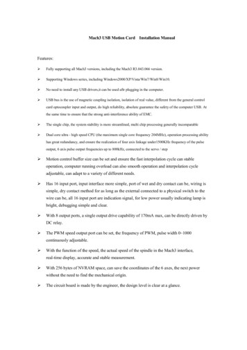
capable of sustaining extended production cycles free from human intervention and offermaximum levels of control and feedback. With computer automation reaching new plateaus,new industrial processes are undergoing development every day. Conventional CNC machiningis at an arguable apex with a plethora of highly advanced cutting tools and high-power spindlescapable of speeds exceeding 50,000 revolutions per minute.Figure 1: Example of a mold created using high-speed, 5-axis machining.http://www.ewt3dcnc.comAlternatives to conventional CNC machining are presenting themselves as time marchesforth. With the unveiling of processes such as Plasma-Arc or Electro-Chemical Erosion, themanufacturing industry finds itself with many seeming viable options in which to create a part.These high initial investments may leave a company uneasy in making a selection as one must beconfident that they are making a wise long-term investment which will help ensure survivability.Due to the relative cost and versatility, conventional CNC machining remains as a staple ofindustry by making it possible to manufacture large quantities of high-quality goods atunprecedented speed. This rapid, high-tech, production enables further advances in virtually all2
other fields and results in a highly sophisticated world which immerses much of humanity on adaily basis.1.2 The Origins of CuttingCutting as a mechanical process is the removal of material resulting through use of force,typically shear and compressive. Although “cutting” is certainly a cutting process, grinding,milling, and drilling are also cutting processes as they result in material removal through theapplication of appropriate forces. It is important to recognize this disconnect as it separates“conventional” machining from machining. A good example of a machining process which doesnot result in cutting is rolling.Rolling is a machining process in which material is deformed as opposed to removed. Itis possible to substitute material removal for deformation and vice versa, though the two tend tonot be interchangeable as each has its own specific purpose along with relevant advantages anddisadvantages. However, a good machinist understands this and may choose the appropriateprocess in order to maximize efficiency. The technical aspects of machine cutting will bediscussed further in Chapter 2.The first cutting implements were fashioned from any material which may yield a useablesurface or point, typically wood and stone. Tools such as chisels have been found and dated backto 1,500 B.C.E. in Egypt, and saws since the early Stone Age (Michael & Fagan, ). The earlyemergence of these tools is undoubtedly the result of intrinsic simplicity coupled with theabundance of appropriate materials from which to make tools (e.g. flint).3
A good example of a modern machine cutter is a punch press. Typically used in sheetmetal manufacture, a punch press is capable of rapidly cutting semi-intricate shapes in a singlemotion. This is achieved through the use of a crafted die which is applied to a work piece withhigh levels of force. Assuming successful operation, the resulting contact with the cutting andforming surfaces produces a piece which fits the dimensions of the die. This process carries theadvantages of high-speed and a low-cost of production. The disadvantages of this process arereductions in quality control and the limitation of the workable material thickness (hence whythese operations are best suited for sheet metal).The Origins of GrindingGrinding is a process in which an abrasive material is applied with force to induce aneroding effect, commonly used during the finishing of a part. Careful selection and application ofthis technique allows a machinist to feature a part or eliminate surface flaws. Grinding thus findsa few niches throughout the machining process in which it is of high value. The technical aspectsof machine grinding will be discussed further in Chapter 2.4
Figure 2: This image shows the forces involved in grinding, from which one can infer the basic mechanisms and principles(Degarmo, Black, & Kohser, 2003)In Figure 2, Ds and Vs are the diameter and velocity of the wheel, respectively. Vw is thevelocity of the work piece, “a” is the desired thickness of material removed, and hmax is themaximum thickness removed at any one time in the grinding process.Thegrindingthattakes place between a metal file and a work piece is the same as that found between particleladen winds and a canyon. A large number of individual cutting surfaces are applied withconsistent force to remove relatively small portions of material at a high frequency. This tends toexhibit features more reminiscent of eroding, though grinding may also be used as a means ofcutting through more difficult materials.1.3 The Origins of TurningTurning is a process in which the selected material or work-piece is secured at one orboth ends and rotated at a high speed. A cutting tool is then introduced so that material isremoved in a helical pattern. First appearing around 1300 B.C.E., the ancient Egyptians5
performed a crude process which replicates the action of a dedicated lathe. One person woulduse a rope to turn the material (typically wood) while the other would use a cutting tool withtheir hands. This process is improved upon by the Romans by utilizing a simple bow, butremains mostly reserved for woodworking and pottery until the Industrial Age enables practicalmetalworking. The technical aspects of turning will be discussed further in Chapter 2.Figure 3: This is a picture of the Haas Automation TL-1 metal lathe.http://www.haascnc.comSomewhat similar to a mill, a lathe turns the work piece as a cutting tool is introduced. Alathe enables one to produce a part with rotational symmetry, or even perform complex helicalcutting operations. Examples of these products include baseball bats and worm gears, both of6
which would be extremely complicated or impossible on a mill. Thus, lathes hold a dedicatedposition in any machine shop and may even be responsible for the creation of the first true mills.1.4 The Origins of MillingMills are machines which are similar in appearance and style to the drill press but differin function and use. In addition to cutting surfaces on the bottom of a mill bit, the sides areutilized as well. This greatly expands not only the functionality of milling, but also greatlyreduces the need for extremely large inventories consisting of cutting tools which may rarely seeuse. Modern mills employ a variation of cutting tools, such as face, end and ball-mills. Utilizingtools such as these allows for operations such as slot cutting, planning, drilling, contouring, anddie-sinking (though more exist). This broad range of use allows a skilled machinist to tacklemany of the machining tasks commonly encountered. Mills have not always been this versatile,however, and may have in fact begun with rotary filing.Rotary filing is a process in which a specialized file is rotated against the surface of awork-piece. Much like a bastardization of grinding and milling, rotary filing only falls short incomparison to a true mill. A rotary filer may be produced as a dedicated machine, though theoriginal use likely came by means of utilizing a round-type file in a typical lathe. Reciprocatingfiles are similar in function, but are historically distinct as reciprocating files emerge later in timeand do not influence the development of “true mills” (Scott, 2008).7
Figure 4: This is a good example of a small set of rotary files, or burr bits . Note the fluted design indicative of moderntool production.http://www.northerntool.comFigure 5: This is a good example of reciprocating files, retrieved from an article published in a 1943 issue of PopularMechanics. Note the discussion on proper alignment affecting surface finish and material removal rates . One can alsoobserve more clearly the8
http://www.northerntool.comThe actual production of a true mill can be traced to the release of the milling machine in1825 and is attributed to Eli Whitney. The mill appears to have been developed and created bymore than just one person (Woodbury, 1960). Although Whitney is a well-known inventor of thetime, his work ismore focused towards
Conventional Computer numerically controlled (CNC) machining is a technology which has been in existence for some decades and is reaching what appears to be an apex, much in tune to the long history of machine tool evoluti