Transcription
FACILITIES INSTRUCTIONS, STANDARDS,AND TECHNIQUESVolume 3-9METHODS FOR COORDINATINGSYSTEM PROTECTIVE EQUIPMENTInternet Version of this Manual CreatedSeptember 2000FACILITIES ENGINEERING BRANCHDENVER OFFICEDENVER, COLORADOThe Appearance of the Internet Version of This ManualMay Differ From the Original, but the Contents Do NotUNITED STATES DEPARTMENT OF THE INTERIORBUREAU OF RECLAMATIONDECEMBER 1991
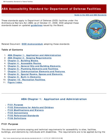
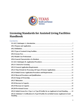
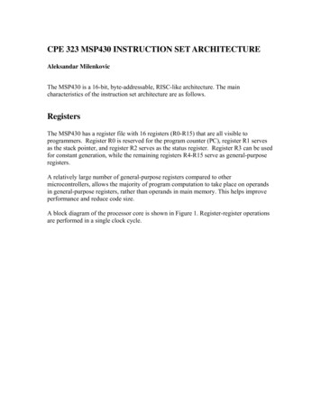
CONTENTSSectionPagePart I-Protective Devices1.Fuses . . . . . . . . . . . . . . . . . . . . . . . . . . . . . . . . . . . . . . . . . . . . . . . . . . . . . . . . 11.1Low-voltage fuses . . . . . . . . . . . . . . . . . . . . . . . . . . . . . . . . . . . . . . . . . . . . . . 21.2Power fuses . . . . . . . . . . . . . . . . . . . . . . . . . . . . . . . . . . . . . . . . . . . . . . . . . . 42.Molded-case circuit breakers . . . . . . . . . . . . . . . . . . . . . . . . . . . . . . . . . . . . . 62.1General . . . . . . . . . . . . . . . . . . . . . . . . . . . . . . . . . . . . . . . . . . . . . . . . . . . . . . 62.2Maintenance . . . . . . . . . . . . . . . . . . . . . . . . . . . . . . . . . . . . . . . . . . . . . . . . . . 73.Overcurrent relays . . . . . . . . . . . . . . . . . . . . . . . . . . . . . . . . . . . . . . . . . . . . . 7Part II-Coordination Study, Characteristics4.One-line diagram . . . . . . . . . . . . . . . . . . . . . . . . . . . . . . . . . . . . . . . . . . . . . . . 85.Short-circuit study6.Current scale selection . . . . . . . . . . . . . . . . . . . . . . . . . . . . . . . . . . . . . . . . . . . 87.Characteristic curves . . . . . . . . . . . . . . . . . . . . . . . . . . . . . . . . . . . . . . . . . . . . 8. 88. Selective coordination . . . . . . . . . . . . . . . . . . . . . . . . . . . . . . . . . . . . . . . . . . . . 9Bibliography . . . . . . . . . . . . . . . . . . . . . . . . . . . . . . . . . . . . . . . . . . . . . . . . . . . . . . 10Figures1. Power fuse dropout test instructions . . . . . . . . . . . . . . . . . . . . . . . . . . . . . . . . . 112. Typical time-current curves of a 600-ampere, frame-size,molded-case circuit breaker . . . . . . . . . . . . . . . . . . . . . . . . . . . . . . . . . . . . . . 123. Typical coordination of transformers, fuses, relays, and breakers . . . . . . . . . . 134. Fault currents in per unit of 3-phase-fault currents for various faultsand transformer connections . . . . . . . . . . . . . . . . . . . . . . . . . . . . . . . . . . . . . . 14i
PART I - PROTECTIVE DEVICESToday, protective devices, including fuses, circuitbreakers, and relays of various types, are quitesophisticated compared to the ones used 20 yearsago. The protective device provides a form ofinsurance for high-cost electrical equipment.Protection of electrical power systems can reducethe extent and duration of an interruption, as wellas reduce equipment damage or personal injury.if a protective device operates, it does so becauseit reacts to a problem in the system. It is vital then,to investigate the cause and location of the prob lem; to merely replace the fuse element or resetthe protective device does not eliminate the prob lem. If the cause of the problem cannot be found,contact D-8440 or D-8450 as to possible reasonsthe protective device operated.1. FUSESA fuse appears to be a simple device, but study ofthe numerous types and circuit applications re veals that it is a complex equipment protectiondevice. Various circuit applications require thatfuses satisfy many requirements includingdifferent interrupting ratings, peak let-through cur rent, (I2t) characteristics, and melting time-currentcharacteristics. A fuse is a thermal tripping devicein an electric circuit the operation of which de pends on thermal capacity of the fuse element, itsmelting temperature (to some extent), and thecurrent flow previous to the fault condition.The fusible element may be composed of any ofthe following metals: bismuth, cadmium, lead, tin,silver, copper, aluminum, or any alloy of theseelements, to achieve thermal characteristics nec essary for best system protection. Measurement ofcapacity of a particular fuse to perform a certainjob depends largely upon the accuracy with whichit was manufactured, the correctness ofapplication, and the quality of maintenance afterinstallation. A fuse improperly applied ormaintained might fail to disconnect the circuitwhen required, which might result in considerabledamage to costly equipment.acting element protects against short-circuit cur rents similar to all ordinary standard fuse. A timedelay element permits short duration overloadsbut melts if an overload is sustained. The mostimportant application of this type of fuses is formotor or transformer protection because it doesnot open on motor starting or transformermagnetizing inrush currents but prevents damagefrom sustained overloadsWhere new protective equipment is being pre scribed such as distribution cutouts, fuse links,secondary fuses, power fuses, distributionenclosed single-pole air switches, fusedisconnecting switches, and accessories for useunder unusual conditions, D-8440 should berequested to provide assistance during design andinstallation of the equipment.Unusual or extreme operating conditions for afuse could be: explosive dust or gas, excessive orabrasive dust, corrosive or conductive vapors,steam, salt water, excessive moisture or drippingwater, excessive vibration or shock, or unusuallylow temperatures. Unusual conditions are some times created by poor storage, transportation, orlimited space conditions, frequencies other than60 Hz, poor maintenance, and infrequency ofoperation.Unusual operating conditions due to ambienttemperature above 40 EC (100 EF):Equipment designed for standard temperaturerise may be used at the normal ratedcontinuous current without exceeding ultimatestandard temperature limits, provided theambient temperature does not exceed 40 EC(100 EF) times the ambient temperature factor(table 1) which corresponds to the altitudewhere the equipment will operate.Unusual operating conditions due to altitudeshigher than 1000 m (3300 ft) above sea level:Equipment that depends on air for insulatingand cooling will have a larger temperature rise.A dual element or time-delay fuse has currentresponse elements of two different fusing charac teristics in series in a single cartridge. A fast-1(FIST 3-9 12/91)
and lower dielectric value and current rating,when operating above 1000 m (3300 ft) eleva tion. The dielectric-strength factor andcontinuous-current factor (table 1) must bemultiplied by the respective values according tothe altitude where the equipment will operate.1.1 LOW-VOLTAGE FUSES.-Design features forfuse applications of 600 V or lower mustcorrespond to UL (Underwriters Laboratories)standards in order to be considered for properselection, as follows:Frequency ratingMaximum peak let-through currentMaximum clearing thermal energy (I2t)Interrupting rating.-Determine the maximumsymmetrical short-circuit available on thesystem at the fuse location. Select a fusehaving an interrupting capacity greater than,the available short-circuit current.Voltage rating.-Voltage rating of a fuseshould be selected as equal to, or greaterthan, the nominal system voltage on which itis used. This rating is not a measure of itsability to withstand a specified voltage whilecarrying current, but rather it is the ability ofthe fuse to prevent the open-circuit voltageof the system from restriking and establish ing an arc once the fuse link has parted.Standard low-voltage ratings are 600, 300,250, and 125 V.Continuous current rating.-The continuouscurrent rating of a fuse should be equal to, orslightly less than, the current-carryingcapacity of the circuit it is protecting. Only inunusual cases (as mentioned earlier) shouldthe fuse rating be greater than the currentcarrying capacity of the circuit. The ambient temperature affects thecurrent-carrying capacity of fuses(table 1).Time-current characteristic.-The fuse timecurrent characteristic should be compatible withthe time-current characteristic of the load andthe time- current characteristic of the circuitcomponents to be protected. Select very fast-acting fuses toprotect very low withstandcomponents, such as semiconductors. Select non-time-delay fuses forresistance currents or other currentswhere no transients or surges areencountered (usually sized at 125percent of full- load amperes). Select a dual-element, time-delayfuse where high inrush or startingloads are present as with motors,solenoids, or control transformers(usually sized at 125 percent of fullload amperes). Select a limiter, or non-time-delayfuse, where short-circuit protectiononly is required (usually sized at 150to 300 percent of circuit ampererating). Test the selected fuse in the intendedcircuit under all normal circuitconditions. This may include transient,inrush, or any other non-steady-statecurrents. For overload and short-circuitprotection (generally) select the fuseampere rating at 125 percent of thefull-load amperes.1.1.1. Plug fuses.-Low-voltage fuses are of twogeneral types, plug and cartridge. Plug fusesare rated at 125 V or less and up to 30 Amaximum and have no interrupting rating. Theyare subject to one alternating-current, shortcircuit test with an available current not over10,000 A, rms. For short-circuit-only protection,select fuse ampere rating at 150 to300 percent of equipment or circuitrating.1.1.2. Cartridge fuses.-Cartridge fuses can beeither renewable or nonrenewable. Arenewable-fuse can be disassembled to replacethe fused element but is generally(FIST 3-9 12/91)2
Table 1. - Altitude correction factorsAltitude abovesea 0490055006100(Feet)3 0004 0005 0006 0007 0008 0009 00010 00012 00014 00016 00018 00020 000Factor to be applied to 9200.8960.8720.8480.8240.800NOTE: Use one correction factor from column 2 or 3, but not both, for any one application. If the deratingas determined from the table is significant, equipment of suitable higher rating should be chosen to meetrequirements after the correction factor has been applied.not available in higher current interruptingratings. The nonrenewable fuse must becompletely replaced when expended. Currentlimiting fuses, a type of cartridge fuse, place adefinite upper limit on the peak current andthermal energy and provide equipmentprotection against damage from excessivethermal energy and magnetic stresses. Thecurrent- limiting fuse is most widely used infused motor starters and switches, fused circuitbreakers, and feeder circuits for protection ofbusways and cable.Class K9 -Fair degree of currentlimitation Short-circuit interrupting ratingsare 50,000, 100,000, and 200,000A, rms, symmetrical. Current ratings up to 600 A. Voltage ratings of 250 and 600 Valternating current only. Interchangeable with UL class H,NEMA class H, and UL class RK1and RK5 fuses in equipment pro vided with class H fuseholders. If fuse is time delay, 10-seconddelay at 500 percent rating is required.1.1.2.1. Class K high interrupting-capacityfuses, nonrenewable.Class K1 -High degree of currentlimitationClass K5 -Moderate degree ofcurrent limitation3(F IST 3-9 12/91)
1.1.2.2. Class R current-limiting fuse,nonrenewable.Class RK1 - High degree of currentlimitations Current rating of 601 to 6,000 A. Voltage rating of 600 V alternating currentonly.Class RK5 - Moderate degree ofcurrent limitations Short-circuit interrupting200,000 A, symmetrical.ratingof Fuses may be marked "time delay"although UL does not investigate timedelay characteristics of such fuses. Current rating up to 600 A. Voltage rating of 250 and 600 V al ternating current only. Interchangeable with UL class H,NEMA class H, and UL classes K1,K5, and K9 in equipment providedwith class H fuseholders. Not inter changeable with any other fuse classin equipment provided with class Hfuseholders. Time delay optional, minimum 10 second delay at 500 percent currentrating.Short-circuit interrupting rating of200,000 A, rms, symmetrical. Short-circuit rating cannot be over 10,000A, rms, symmetrical. Current ratings up to 600 A. Voltage rating of 250 and 600 V al ternating current only. May or may not be dual element, iflabeled as "time delay" it must have aminimum 10-second delay at 500percent current rating.Current rating up to 600 A. Voltage rating of 600 V alternatingcurrent only. Not interchangeable with any otherfuse class. Fuses having a time delaycharacteristic are available in class Jdimensional sizes although they donot meet the UL standards for currentlimiting performance.1.1.2.4. Class L current-limiting fuses,nonrenewable.-(FIST 3-9 12/91)1.1.2.5. Class H non-current-limitingfuses constructed in both renewable (time delayoptional) and nonrenewable(no time delay) configurations.- Interchangeable with UL classes K1, K5,and K9, NEMA class H, and UL classesRK1 and RK5 fuses in equipmentprovided with class H fuseholders.1.1.2.3. Class J current-limiting fuses,nonrenewable.- Short-circuit interrupting rating200,000 A, rms, symmetrical. Not interchangeable with any other fuseclass.of41.2. POWER FUSES.-The selection of a powerfuse, which is a fuse rated over 600 V, should bebased on the following considerations. A powerfuse consists of an assembly of a fuse supportand a fuseholder which may or may not includethe refill unit or fuse link. Power fuses provideconsistent and fast protection for equipment shortcircuits where it is not economically advisable touse a circuit breaker. Power fuses are usuallyused for primary or secondary protection of powertransformers but are also used for feeder circuitsand capacitor banks. Because power fuses are notdesigned for automatic restoration of service butrequire manual replacement of the fused ele-
ment, it is not advisable to use them whereoverloads may occur frequently.1.2.1. Current-limiting fuses.-To obtain ahigh-interrupting capacity starter on systemsabove 600 V, these fuses were primarilydeveloped for use with motor-startingcontactors to limit the short-circuit current toa value within the "withstand capabilities" ofthe contactors. Other typical applications ofcurrent-limiting fuses are protection ofpotential transformers and protection ofsmall loads on high-capacity circuits. Due tothe time-current characteristics of powerfuses being near vertical, it makes themdifficult to coordinate with overcurrent relayson their load side.1.2.2. Expulsion-type fuses.-Generallyused in distribution system cutouts or dis connecting switches, this type of fuse mustuse an arc-confining tube with deionizingfiber liner to interrupt a fault current. The arcis interrupted by the rapid production of thepressurized gas within the fuse tube whichextinguishes the arc by expulsion from theopen end, or ends, of the fuse. This processis comparatively noisy and, if applied with anenclosure, care must be taken to vent anyionized gases which would cause a flash over between internal live parts. Fuses rated above 100 A shall meltin 600 seconds at an rms current withinthe range of 220 to 264 percent of thecontinuous rating of the fuse element.Some power fuse elements comply with theNEMA standard "N" rating which has the followingcharacteristic requirements: The current rating of the fuse must becarried continuously. The element will melt in 300 to 600seconds at an rms current within 115to 125 percent of the continuousrating.To provide the best possible coordination, powerfuse elements are available in three speed ratios:fast, medium, and low. The speed ratio of a fuseelement is defined as the ratio of the minimummelting current at 0.1 second to the minimummelting current at 300 seconds for fuses rated 100A or less and 600 seconds for fuses rated above100 A. These values can be obtained from themanufacturer (time-current characteristic curveson the particular ampere rating and type of fuseelement).1.2.4. Power fuse ratings.-Power fuses shouldbe selected on the basis of the following ratings:1.2.4.1. Current rating.-The current rating of afuse element must be large enough to handlethe following normal short-time overloads,energizing, and switching surges under normaloperating conditions without operating.1.2.3. Power fuse element characteristics.-For any given element melting time,the maximum steady-state symmetricalcurrent shall not exceed the minimum bymore than 20 percent.Most power fuse elements comply withNEMA standard "E" rating which has thefollowing characteristic requirements: Short-time daily overloads within thelimits recommended by ANSI C57.92,1962. The current rating of the fuse must becarried continuously. Transformer magnetizing inrushcurrent of 12 times the transformerfull-load current for 0.1 second (theinrush current may be as high as 20 to25 times full-load current for somedry-type transformers). Fuses rated at 100 A or less shall meltin 300 seconds at an rms current withinthe rate of 200 to 240 percent of thecontinuous rating of the fuse element.5(FIST 3-9 12/91)
Switching surges normally experi enced on a utility system. Refinish fuse tubes made of organic (class"A") material as required and specified bythe manufacturer. Ambient temperature up to 40EC.1.2.4.2. Voltage rating.-The voltage ratingof a fuse should be selected as equal toor greater than the nominal systemvoltage on which it is used.1.2.4.3. Interrupting current rating.-Determine the maximum asymmetricalshort-circuit current available on the sys tem at the fuse location. Select a fusehaving a current interrupting ratinggreater than the available short-circuitcurrent.1.2.4.4. Frequency rating.-Fifty or sixtyhertz.1.2.5. Inspection of power fuses.-Inspectionof power fuses should be done at intervals thatare a function of the conditions at a given fuselocation and must be determined by the user(generally 1-year intervals). A summary ofspecial considerations based on ANSI C37.48for fuse inspection follows: Make sure that the fuse isdisconnected from all power sourcesbefore servicing If applicable, clean the insulators andinspect them for breaks, cracks, orburns. The insulators should be cleanto avoid flashover as a result ofaccumulation of foreign substanceson insulator surfaces where abnormalconditions exist. Check the lock or latch, and check forloss and condition of bolts, nuts,washers, pins, and terminalconnectors. Inspect contact surfaces for burning,pressure, pitting, and alignment.Badly pitted or burned contacts shouldbe replaced.(FIST 3-9 12/91)6 Examine the fuse tube, renewableelement, and fuse unit for corrosion ofthe fuse element or connectingconductors, excessive erosion of theinside of fuse tubes, discharge (tracking)and dirt on the outside of the fuse tube,and improper assembly that may preventproper operation. Replace fuse units ortubes that show signs of deterioration.1.2.6. Power fuse tests.-Refer to ANSIC37.41 and figure 1 for procedure in fusetests and test procedure of fuse-mountingequipment. Refer to ANSI C37.46 for perfor mance characteristics of fuse units, refillunits, and fuse links for power fuses.2. MOLDED-CASE CIRCUIT BREAKERS2.1 GENERAL.-New models of molded-casecircuit breakers are available, equipped withsuch features as adjustable long-time delayelements and solid- state construction. Thebasic design is an electromechanical-type tripdevice rated to carry 100 percent of rated con tinuous current when tested in the open at 25EC ambient temperature (location in an en closure requires derating and a thermal tripelement having a special 40 EC ambient tem perature calibration compensation). The properapplication of a molded-case circuit breakergoes beyond consideration of the basic voltage,current, and interrupting rating. Coordinationbetween source and load side protectivedevices is required. A typical time-currentcharacteristic curve (fig. 2) for a circuit breakeris shown. The units are sealed, andmaintenance of the internal mechanism is notpossible.If a molded-case circuit breaker is equippedwith time delay and adjustable instantaneoustrip element, adjust the instantaneous trip nohigher than necessary to avoid nuisance trip ping. Make sure that the instantaneous tripsettings do not exceed the available short-cir-
cuit current at the location of the circuit breakeron the system. The time delay characteristic isgenerally a thermal element composed of abimetal strip; however, some manufacturers usea magnetic sensing device with a dashpot forthe time delay characteristic.2.2. MAINTENANCE.-Keep the circuit breakersclean and dry. If a breaker is located in a dirtyor dusty atmosphere, frequently remove andblow it out with clean, dry, low-pressure air.Caution: DO NOT blow the dirt into the re cesses of the unit.Check for heating due to poor electrical con nections, improper trip unit alignment, or im proper mechanical connections within the circuitbreaker housing. Abnormal heating is evidentby discoloration of terminals, deterioration ofmolded material, or nuisance tripping. If any ofthese abnormal heating symptoms exist, locatethe cause by making the following checks: Check the load current.-The currentin each of the individual polesshould be less than the circuitbreaker rating; if not, all boltedconnections and contacts should beexamined and tightened to themanufacturer's specifications. Check the trip coil.-An open turn or ter minal could cause failure to trip. Foreign matter may be preventing move ment of the following breaker parts: tripbar, armature, latch release, trigger, bi metal, bellows or dashpot, or spring as semblies.The testing procedure of molded-case circuitbreakers (IEEE Standard 242-1975, paragraph15.3.1.) or NEMA publication "Procedures forVerifying Performance of Molded-Case CircuitBreakers" may be used as an alternate guide fortesting molded-case circuit breakers.3. OVERCURRENT RELAYSElectromagnetic attraction, induction, and solid-stateovercurrent relays are usually used for short-circuitprotection of low-voltage systems. When a relayoperates, it initiates a circuit breaker trippingoperation to isolate the fault from the rest of thesystem. Overcurrent relays with voltage control candistinguish between overload and fault conditionsbecause a short circuit on an electrical system isalways followed by a corresponding voltage dip;whereas, an overload causes only a moderate dip.There are two types of overcurrent relays: Instantaneous overcurrent relays operatewithout intentional time delay. Check the movement of the tripbar.-Excessive friction or binding ofthe trip bar will not allow the bimetalto exert sufficient pressure to movethe trip bar. The mechanism shouldbe adjusted or lubricated. Time delay relays to allow transient currentscaused by sudden overloads of briefduration. Most overcurrent relays are of thistype, with time delay features to allowcurrent several times in excess of thesetting for a limited time without closing thecontacts. A relay with an inverse timecharacteristic operates faster as currentincreases. Check the bimetal or dashpot.-Adefective bimetal or dashpot couldalter the operating characteristics.7(FIST 3-9 12/91)
PART II-COORDINATION STUDY, CHARACTERISTICSThe objective of a coordination study is to deter mine the characteristics, ratings, and settings ofovercurrent protective devices which will ensurethat minimum unfaulted load is interrupted whenprotective devices isolate a fault or overloadanywhere in the system. A coordination studyshould be conducted in the early planningstages of a new system to tentatively selectprotection and utilization equipment. In the casewhere an existing system is modified and newloads are installed, or when existing equipmentis replaced with higher rated equipment, acoordination study should be conducted.The following paragraphs describe briefly the in formation required for performing a coordinationstudy: Current transformer ratios. Relay, circuit breaker and fuse ratings,characteristics, and ranges of adjust ment.5. SHORT-CIRCUIT STUDYObtain or perform a complete short-circuit studyproviding momentary and interrupting ratings.The study should also include maximum andminimum expected fault interrupting duties, aswell as contributions from each short-circuitcurrent source. Gather time-current characteristiccurves for each protective device underconsideration.6. CURRENT SCALE SELECTION4. ONE-LINE DIAGRAMWhether the study is on an existing or a newsystem, obtain or produce a one- line diagramof the system or the portion of the systeminvolved. When plotting time-currentcoordination curves, certain time intervals mustbe maintained between curves or variousprotection devices in order to ensure correctsequential operation of the devices. Theseprotective (time) margins allow for mechanicalovertravel, time delays in circuit opening,manufacturer's tolerance, and calibration error.Because the overall objective of the coordinationstudy is to achieve time- sequenced tripping ofovercurrent protective devices, such that the de vice closest to the fault condition trips first, thecharacteristic curve of the device closest to theload is plotted as far to the left of a 4- by 4-cyclelog-log graph as possible so that the source sidecharacteristic curves are not crowded to the rightof the paper. The maximum short-circuit currentof the system is the right-hand limit of thecurves.7. CHARACTERISTIC CURVESThe diagram should show the following data: Apparent power and voltage ratings aswell as the impedance ratings and con nections of all transformers. Normal and emergency switching condi tions. Nameplate ratings and subtransientreactance of all major motors andgenerators as well as transientreactances of synchronous motors andgenerators, plus synchronousreactances of generators. Conductor sizes, types, and configura tions.(FIST 3-9 12/91)8Plot on the time-current, Iog-log paper the fixedand continuous points of all electrical devicesunder consideration. A typical coordination plotfor protection of a transformer is shown (fig. 3).Note: In the process of plotting the time-current characteristic curves, it must be remem bered that all currents must be referred to acommon voltage, either primary orsecondary, before attempting to determinecoordination. On a delta-wye system, thecurrent that the primary fuse sees due to asecondary fault depends on the type of fault,as well as the severity of the fault. Figure 4shows several unbalanced faults for deltawye and wye-delta transformers and thecurrent relationships of the windings and lineconductors.
Plot the total symmetrical and asymmet rical short-circuit current available to thepower system at the fault point (plot boththree-phase and line ground fault-currentmagnitudes).The time intervals shown below must be main tained between the curves of various protectiondevices to allow for mechanical overtravel, timedelays in circuit opening, manufacturer'stolerance, and calibration error: Also plot the full-load current and heatingcurve of every transformer (from tiletransformer manufacturer).8.1 RELAYS require a protection margin (with0.3 to 0.4 second allowed between device curvesto ensure noncascading) between device curvesof: Plot the short-circuit capability (trans former damage curve) curve. If thiscurve is not available from the manufac turer, the data in Table 2 below fromAmerican Standard C57.12-1968 may beused for oil-cooled transformers. Linecurrents should be used, otherwise for adelta-wye system a shift of the plot by0.577 or 1/ 3 is required. Plot the transformer inrush current point,which is normally 12 times full- load cur rent at 0.1 second. Plot the locked rotor current, accelerationtime, and full-load current of large motors. Plot the time-current characteristics of allrelays, circuit breakers, and fuses.8. SELECTIVE COORDINATIONThe time-current characteristic curves of protec tive devices should not overlap if selectivecoordination is to be achieved, nor should theprimary device of the transformer trip on inrush.The protective devices must be set to protectcables, motors, and system equipment from overlap as well as short- circuit conditions. Circuit breaker opening time 0.08second. Circuit breaker overtravel 0.10 second. Safety factor 0.12 to 0.22 second.8.2. FUSES require a protection margin betweendevice curves, which is determined byplotting both total clearing time curve andminimum melting time curve. One essential rulefor application of fuse links statesthat thernaximum clearing time of the downstream(protecting) link shall not exceed 75 percent of theminimum melt time of the next upstream(protected) link. This principle assures that theprotecting link will interrupt and clear the faultbefore the protected link is damaged in any way.This is usually about 0.1 second.8.3 LOW-VOLTAGE CIRCUIT BREAKERcurves can get close but should not overlap. Thislack of a definedtime margin is explained bythe incorporation of all variables plus the circuitbreaker operating times of these devices withina band of the device characteristic curve.Table 2 - Transformer Winding Short-Circuit CapabilitySymmetrical Current in Any WindingTime Period in Seconds25 times base current220 times base current316.6 times base current414.3 times base current5The base current is from the self-cooled (OA) rating9(FIST 3-9 12/91)
BIBLIOGRAPHY[1] "Recommended Practice for Protection andCoordination of Industrial and Commercial PowerSystems," IEEE (Institute of Electrical and Elec tronics Engineers, Inc.), Std. No. 242-1975, par.7.5.2, New York, N.Y., 1975.[2] "Recommended Practice for Electric PowerDistribution for Industrial Plants," IEEE, Std. No.141-1976, 5th ed., New York, N.Y., 1976.[3] "Standard Dictionary of Electrical and Electron
Protection of electrical power systems can reduce the extent and duration of an interruption, as well as reduce equipment damage or personal injury. if a protective device operates, it does so because it reacts to a problem in the system. It is vital th