Transcription
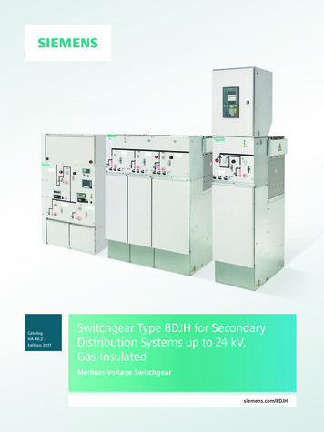
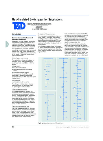
Gas-Insulated Switchgear for SubstationsCABLE JOINTS, CABLE TERMINATIONS, CABLE GLANDS, CABLE CLEATSFEEDER PILLARS, FUSE LINKS, ARC FLASH, CABLE ROLLERS, CUT- OUTS11KV 33KV CABLE JOINTS & CABLE TERMINATIONSFURSE EARTHINGwww.cablejoints.co.ukThorne and Derrick UKTel 0044 191 490 1547 Fax 0044 191 477 5371Tel 0044 117 977 4647 Fax 0044 117 9775582Introduction123Common characteristic features ofswitchgear installationBecause of its small size and outstandingcompatibility with the environment, SF6 insulated switchgear (GIS) is gaining constantly on other types. Siemens has beena leader in this sector from the very start.The concept of SF6 - insulated metal-enclosed high-voltage switchgear has proveditself in more than 70,000 bay operatingyears in over 6,000 installations in all partsof the world. It offers the following outstanding advantages.Protection of the environmentThe necessity to protect the environmentoften makes it difficult to erect outdoorswitchgear of conventional design, whereas buildings containing compact SF6-insulated switchgear can almost always bedesigned so that they blend well with thesurroundings.SF6-insulated metal-enclosed switchgearis, due to the modular system, very flexibleand can meet all requirements of configuration given by network design and operating conditions.Each circuit-breaker bay includes the fullcomplement of disconnecting and grounding switches (regular or make-proof),instrument transformers, control and protection equipment, interlocking and monitoring facilities commonly used for thistype of installation (Fig. 39).Beside the conventional circuit-breakerbay, other arrangements can be suppliedsuch as single-bus, ring cable with load-breakswitches and circuit-breakers, single-busarrangement with bypass-bus, coupler andbay for triplicate bus. Combined circuitbreaker and load-break switch feeder, ringcable with load-break switches, etc. arefurthermore available for the 145 kV level.Minimal space requirements456The availability and price of land play animportant part in selecting the type ofswitchgear to be used. Siting problemsarise in Large towns Industrial conurbations Mountainous regions with narrowvalleys Underground power stationsIn cases such as these, SF6-insulatedswitchgear is replacing conventionalswitchgear because of its very small spacerequirements.Full protectionagainst contact with live parts7The all-round metal enclosure affordsmaximum safety for personnel underall operating and fault conditions.Protection against pollution8910Its metal enclosure fully protects theswitchgear interior against environmentaleffects such as salt deposits in coastalregions, industrial vapors and precipitates,as well as sandstorms. The compactswitchgear can be installed in buildingsof uncomplicated design in order to minimize the cost of cleaning and inspectionand to make necessary repairs independent of weather conditions.Free choice of installation siteThe small site area required for SF6-insulated switchgear saves expensive gradingand foundation work, e.g. in permafrostzones. Other advantages are the shorterection times and the fact that switchgearinstalled indoors can be serviced regardless of the climate or the weather.Fig. 39: Typical circuit arrangements of SF6-switchgear2/28Siemens Power Engineering Guide · Transmission and Distribution · 4th Edition
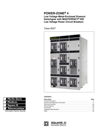
Gas-Insulated Switchgear for SubstationsMain product range of GISfor substationsSF6 switchgear up to 550 kV(the total product range covers GIS from66 up to 800 kV rated voltage): Fig. 40.The development of the switchgear isalways based on an overall production concept, which assures the achievement ofthe high technical standards requiredof the HV switchgear whilst providing themaximum customer benefit.This objective is attained only by incorporating all processes in the quality management system, which has been introducedand certified according to DIN EN ISO9001 (EN 29001).Siemens GIS switchgear meets allthe performance, quality and reliabilitydemands such as:Compact space-saving designmeans uncomplicated foundations, a widerange of options in the utilization of space,less space taken up by the switchgear.Minimal-weight constructionthrough the use of aluminum alloy and theexploitation of innovations in developmentsuch as computer-aided design tools.1Safe encapsulationmeans an outstanding level of safetybased on new manufacturing methodsand optimized shape of enclosures.2Environmental compatibilitymeans no restrictions on choice of locationthrough minimal space requirement, extremely low noise emission and effectivegas sealing system (leakage 1% per yearper gas compartment).3Economical transport35004740means simplified and fast transport andreduced costs because of maximum possible size of shipping units.4480285034705170500Switchgear type8DN88DN98DQ1Details on page2/302/312/324Minimal operating costsmeans the switchgear is practically maintenance-free, e.g. contacts of circuit-breakersand disconnectors designed for extremelylong endurance, motor-operated mechanisms self-lubricating for life, corrosion-freeenclosure. This ensures that the first inspection will not be necessary until after25 years of operation.56ReliabilityRated voltage[kV]up to 145up to 245up to 550Rated powerfrequencywithstand voltage[kV]up to 275up to 460up to 740Rated lightningimpulse withstandvoltage[kV]up to 650up to 1050up to 1800Rated switchingimpulse withstandvoltage[kV]–up to 850up to 1250Rated (normal) current [A]busbarup to 3150up to 3150up to 6300Rated (normal) current [A]feederup to 2500up to 3150up to 4000Rated breakingcurrent[kA]up to 40up to 50up to 63Rated short-timewithstand current[kA]up to 40up to 50up to 63Rated peakwithstand current[kA]up to 108up to 135up to 170 25 25 258001200/15003600means our overall product concept whichincludes, but is not limited to, the use offinite elements method (FEM), threedimensional design programs, stereolithography, and electrical field developmentprograms assuring the high standard ofquality.Smooth and efficientinstallation and commissioning78transport units are fully assembled andtested at the factory and filled with SF6 gasat reduced pressure. Plug connection of allswitches, all of which are motorized, further improves the speediness of site installation and substantially reduces field wiringerrors.9Routine testsInspection[Years]Bay width[mm]All dimensions in mmAll measurements are automatically documented and stored in the EDP informationsystem, which enables quick access tomeasured data even if years have passed.For further information please contact:Fax: 49- 9131-7-34498e-mail: evhgis@erls04.siemens.deFig. 40: Main product rangeSiemens Power Engineering Guide · Transmission and Distribution · 4th Edition2/2910
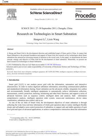
Gas-Insulated Switchgear for Substations12345678910SF6-insulated switchgearup to 145 kV, type 8DN8Three-phase enclosures are used for type8DN8 switchgear in order to achieve extremely low component dimensions. Thelow bay weight ensures minimal floorloading and eliminates the need for complexfoundations. Its compact dimensions andlow weight enable it to be installed almostanywhere. This means that capital costs canbe reduced by using smaller buildings, orby making use of existing ones, for instancewhen medium voltage switchgearis replaced by 145 kV GIS.The bay ist based on a circuit-breakermounted on a supporting frame (Fig. 41).A special multifunctional cross-couplingmodule combines the functions of the disconnector and earthing switch in a threeposition switching device. It can be used as an active busbar with integrated disconnector and work-in-progress earthingswitch (Fig. 41/Pos. 3 and 4), outgoing feeder module with integrateddisconnector and work-in-progress earthing switch (Fig. 41/Pos. 5), busbar sectionalizer with busbar earthing.For cable termination, a cable terminationmodule can be equipped with either conventional sealing ends or the latest plug-inconnectors (Fig. 41/Pos. 9). Flexible singlepole modules are used to connect overheadlines and transformers by using a splittingmodule which links the 3-phase encapsulatedswitchgear to the single pole connections.Thanks to the compact design, up to threecompletely assembled and works-testedbays can be shipped as one transport unit.Fast erection and commissioning on siteensure the highest possible quality.The feeder control and protection can belocated in a bay-integrated local controlcubicle, mounted in the front of each bay(Fig. 42). It goes without saying that wesupply our gas-insulated switchgear with alltypes of currently available bay control systems – ranging from contactor circuit controls to digital processor bus-capable baycontrol systems, for example the modernSICAM HV system based on serial buscommunication. This system offers Online diagnosis and trend analysis enabling early warning, fault recognition andcondition monitoring. Individual parameterization, ensuring thebest possible incorporation of customizedcontrol facilities. Use of modern current and voltage sensors.This results in a longer service life and loweroperating costs, in turn attaining a considerable reduction in life cycle costs.2/3071286Gas-tight bushingGas-permeable bushing1054935 Outgoing feeder module1 Interrupter unit of thecircuit-breaker2 Spring-stored energymechanism with circuit-breakercontrol unit3 Busbar I with disconnectorand earthing system4 Busbar II with disconnectorand earthing system678910with disconnector andearthing switchMake-proof earthing switch(high-speed)Current transformerVoltage transformerCable sealing endIntegrated local control cubicle34175869Fig. 41: Switchgear bay 8DN8 up to 145 kVFig. 42: 8DN8 switchgear for rated voltage 145 kVFig. 43Siemens Power Engineering Guide · Transmission and Distribution · 4th Edition
Gas-Insulated Switchgear for SubstationsSF6-insulated switchgearup to 245 kV, type 8DN9The clear bay configuration of the lightweight and compact 8DN9 switchgear isevident at first sight. Control and monitoringfacilities are easily accessible in spite ofthe compact design of the switchgear.The horizontally arranged circuit-breakerforms the basis of every bay configuration.The operating mechanism is easily accessible from the operator area. The other baymodules – of single-phase encapsulateddesign like the circuit-breaker module – arelocated on top of the circuit-breaker. Thethree-phase encapsulated passive busbaris partitioned off from the active equipment.Thanks to “single-function” assemblies(assignment of just one task to each module)and the versatile modular structure, evenunconventional arrangements can be setup out of a pool of only 20 different modules.The modules are connected to each otherby a standard interface which allows anextensive range of bay structures. Theswitchgear design with standardized modules and the scope of services mean thatall kinds of bay structures can be set up ina minimal area.The compact design permits the supply ofdouble bays fully assembled, tested in thefactory and filled with SF6 gas at reducedpressure, which assures smooth and efficient installation and commissioning.The following major feeder control levelfunctions are performed in the local controlcubicle for each bay, which is integrated inthe operating front of the 8DN9 switchgear: Fully interlocked local operation andstate-indication of all switching devicesmanaged reliably by the Siemens digitalswitchgear interlock system Practical dialog between the digital feeder protection system and central processor of the feeder control system Visual display of all signals required foroperation and monitoring, together withmeasured values for current, voltage andpower Protection of all auxiliary current andvoltage transformer circuits Transmission of all feeder information tothe substation control and protectionsystemFactory assembly and tests are significantparts of the overall production conceptmentioned above. Two bays at a time undergo mechanical and electrical testingwith the aid of computer-controlled stands.144637Gas-tight bushingGas-permeable bushing1091215234521 Circuit-breaker interrupter unit2 Spring-stored energy34567mechanism with circuit-breakercontrol unitBusbar disconnector IBusbar IBusbar disconnector IIBusbar IIEarthing switch(work-in-progress)111 81368 Earthing switch(work-in-progress)9 Outgoing-disconnector10 Make-proof earthing switch11121314(high-speed)Current transformerVoltage transformerCable sealing endIntegrated local control cubicle3577111891210813Fig. 44: Switchgear bay 8DN9 up to 245 kVSiemens Power Engineering Guide · Transmission and Distribution · 4th Edition910Fig. 45: 8DN9 switchgear forrated voltage 245 kV2/31
Gas-Insulated Switchgear for Substations1234567SF6-insulated switchgearup to 550 kV, type 8DQ1The GIS type 8DQ1 is a modular switchgear system for high power switching stations with individual enclosure of all modules for the three-phase system.The base unit for the switchgear forms ahorizontally arranged circuit-breaker on topof which are mounted the housings containing disconnectors, grounding switches,current transformers, etc. The busbar modules are also single-phase encapsulatedand partitioned off from the active equipment.As a matter of course the busbar modulesof this switchgear system are passiveelements, too.Additional main characteristic features ofthe switchgear installation are: Circuit-breakers with two interrupterunits up to operating voltages of 550 kVand breaking currents of 63 kA (from63 kA to 100 kA, circuit-breakers withfour interrupter units have to be considered) Low switchgear center of gravity bymeans of circuit-breaker arranged horizontally in the lower portion Utilization of the circuit-breaker transport frame as supporting device for theentire bay The use of only a few modules andcombinations of equipment in one enclosure reduces the length of sealing facesand consequently lowers the risk ofleakage11 10129 871645321312345678Circuit-breakerBusbar disconnector IBusbar IBusbar disconnector IIBusbar IIGrounding switchVoltage transformerMake-proof groundingswitch9 Cable disconnector141011121314151617181516 17 18Grounding switchCurrent transformerCable sealing endLocal control cubicleGas monitoring unit(as part of control unit)Circuit-breaker control unitElectrohydraulic operating unitOil tankHydraulic storage cylinder352461111097812Fig. 46: Switchgear bay 8DQ1 up to 550 kV8910Fig. 47: 8DQ1 switchgear for rated voltage 420 kV2/32Siemens Power Engineering Guide · Transmission and Distribution · 4th Edition
Gas-Insulated Switchgear for SubstationsSome examples for specialarrangementGas-insulated switchgear – usually accommodated in buildings (as shown in a towertype substation) – is expedient wheneverthe floor area is very expensive or restricted or whenever ambient conditions necessitate their use (Fig. 50, page 2/34).For smaller switching stations, or in casesof expansion when there is no advantagein constructing a building, a favorablesolution is to install the substation in acontainer (Fig. 49).1 Cable termination2 Make-proof earthing3456switchOutgoingdisconnectorEarthing switchCircuit breakerEarthing switch7 Current transformer8 Outgoingdisconnector9 Make-proof earthingswitch10 Voltage transformer11 Outdoor terminationFig. 49: 8DN9 switchgear bay in a containerMobile containerized switching stationscan be of single or multi-bay design usinga large number of different circuits andarrangements. All the usual connectioncomponents can be employed, such asoutdoor bushings, cable adapter boxes andSF6 tubular connections. If necessary, allthe equipment for control and protectionand for the local supply can be accommodated in the container. This allows exten-232453678Mobile containerized switchgear –even for high voltageAt medium-voltage levels, mobile containerized switchgear is the state of the art.But even high-voltage switching stationscan be built in this way and economicallyoperated in many applications.The heart is the metal-enclosed SF6-insulated switchgear, installed either in asheet-steel container or in a block housemade of prefabricated concrete elements.In contrast to conventional stationaryswitchgear, there is no need for complicated constructions; mobile switching stations have their own ”building“.119410115Fig. 48: Containerized 8DN9 switchgear with stub feed in this examplesively independent operation of the installation on site. Containerized switchgear ispreassembled in the factory and ready foroperation. On site, it is merely necessaryto set up the containers, fit the exteriorsystem parts and make the external connections. Shifting the switchgear assemblywork to the factory enhances the qualityand operational reliability. Mobile containerized switchgear requires little space andusually fits in well with the environment.Rapid availability and short commissioningtimes are additional, significant advantagesfor the operators. Considerable cost reductions are achieved in the planning, construction work and assembly.Building authority approvals are either notrequired or only in a simple form. The installation can be operated at various locations in succession, and adaptation to localcircumstances is not a problem. These arethe possible applications for containerizedstations: Intermediate solutions for themodernization of switching stations Low-cost transitional solutions whentedious formalities are involved in thenew construction of transformer substations, such as in the procurement ofland or establishing cable routes Quick erection as an emergency stationin the event of malfunctions in existingswitchgear Switching stations for movable, geothermal power plantsSiemens Power Engineering Guide · Transmission and Distribution · 4th EditionGIS up to 245 kV in a standard containerThe dimensions of the 8DN9 switchgearmade it possible to accommodate all activecomponents of the switchgear (circuitbreaker, disconnector, grounding switch)and the local control cabinet in a standardcontainer.The floor area of 20 ft x 8 ft complieswith the ISO 668 standard. Although thecontainer is higher than the standarddimension of 8 ft, this will not cause anyproblems during transportation as provenby previously supplied equipment.German Lloyd, an approval authority, hasalready issued a test certificate for an evenhigher container construction.The standard dimensions and ISO cornerfittings will facilitate handling during transport in the 20 ft frame of a container shipand on a low-loader truck.Operating staff can enter the containerthrough two access doors.Rent a GISContainerized gas-insulated high voltagesubstations for hire are now available. Inthis way, we can step into every breach,instantly and in a remarkably cost-effectivemanner.Whether for a few weeks, months or even2 to 3 years, a fair rent makes our InstantPower Service unbeatably economical.2/33678910
Gas-Insulated Switchgear for SubstationsAll dimensions in mSpecification guide formetal-enclosed SF6-insulatedswitchgearAir conditioningsystem126.902The points below are not considered tobe comprehensive, but are a selection ofthe important ones.Relay roomGeneral23.2034Gas-insulatedswitchgear type8DN9Groundingresistor515.9513.8 kVswitchgear6Applicable standardsShuntreactor11.507Cable duct8.908Radiators40 MVA transformer102.20–1.50Fig. 50: Special arrangement for limited space. Sectional view of a building showing the compact nature ofgas-insulated substations2/34All equipment shall be designed, built,tested and installed to the latest revisionsof the applicable IEC 60 standards (IECPubl. 60517 “High-voltage metal-enclosedswitchgear for rated voltages of 72.5 kVand above”, IEC Publ. 60129 “Alternatingcurrent disconnectors (isolators) andgrounding switches”, IEC Publ. 60056“High-voltage alternating-current circuitbreakers”), and IEC Publ. 60044 for instrument transformers.Local conditionsCompensator9These specifications cover the technicaldata applicable to metal-enclosed SF6 gasinsulated switchgear for switching anddistribution of power in cable and/or overhead line systems and at transformers.Key technical data are contained in thedata sheet and the single-line diagramattached to the inquiry.A general “Single-line diagram” and asketch showing the general arrangementof the substation and the transmission lineexist and shall form part of a proposal.The switchgear quoted shall be completeto form a functional, safe and reliable system after installation, even if certain partsrequired to this end are not specificallycalled for.The equipment described herein will beinstalled indoors. Suitable lightweight,prefabricated buildings shall be quoted ifavailable from the supplier.Only a flat concrete floor will be providedby the buyer with possible cutouts in caseof cable installation. The switchgear shallbe equipped with adjustable supports(feet). If steel support structures are required for the switchgear, these shall beprovided by the supplier.For design purposes indoor temperaturesof – 5 C to 40 C and outdoor temperatures of – 25 C to 40 C shall be considered.For parts to be installed outdoors (overhead line connections) the applicable conditions in IEC Publication 60517 shall alsobe observed.Siemens Power Engineering Guide · Transmission and Distribution · 4th Edition
Gas-Insulated Switchgear for SubstationsWork, material and designAluminium or aluminium alloys shall beused preferabely for the enclosures.Maximum reliability through minimumamount of erection work on site is required. Subassemblies must be erectedand tested in the factory to the maximumextent. The size of the subassemblies shallbe limited only by the transport conditions.The material and thickness of the enclosure shall be selected to withstand an internal arc and to prevent a burn-through orpuncturing of the housing within the firststage of protection, referred to a shortcircuit current of 40 kA.Normally exterior surfaces of the switchgear shall not require painting. If done foraesthetic reasons, surfaces shall be appropriately prepared before painting, i.e. allenclosures are free of grease and blasted.Thereafter the housings shall be paintedwith no particular thickness required butto visually cover the surface for decorativereasons only. The interior color shall belight (white or light grey).All joints shall be machined and all castings spotfaced for bolt heads, nuts andwashers.Assemblies shall have reliable provisionsto absorb thermal expansion and contractions created by temperature cycling. Forthis purpose metal bellows-type compensators shall be installed. They must beprovided with adjustable tensioners.All solid post insulators shall be providedwith ribs (skirts).For supervision of the gas within the enclosures, density monitors with electricalcontacts for at least two pressure levelsshall be installed. The circuit-breakers,however, might be monitored by densitygauges fitted in circuit-breaker controlunits.The manufacturer assures that the pressure loss within each individual gas compartment – and not referred to thetotal switchgear installation only – will benot more than 1% per year per gas compartment.Each gas-filled compartment shall beequipped with static filters of a capacityto absorb any water vapor penetrating intothe switchgear installation over a periodof at least 25 years.Long intervals between the necessary inspections shall keep the maintenance costto a minimum. A minor inspection shallonly become necessary after ten years anda major inspection preferably after a periodexceeding 25 years of operation, unlessthe permissible number of operations ismet at an earlier date.Arrangement and modulesArrangementThe arrangement shall be single-phase orthree-phase enclosed.The assembly shall consist of completelyseparate pressurized sections designedto minimize the risk of damage to personnel or adjacent sections in the event of afailure occurring within the equipment.Rupture diaphragms shall be provided toprevent the enclosures from uncontrolledbursting and suitable deflectors provideprotection for the operating personnel.In order to achieve maximum operatingreliability, no internal relief devices maybe installed because adjacent compartments would be affected.Modular design, complete segregation,arc-proof bushings and “plug-in” connection pieces shall allow ready removal ofany section and replacement with minimum disturbance of the remaining pressurized switchgear.BusbarsAll busbars shall be three-phase or singlephase enclosed and be plug-connectedfrom bay to bay.Circuit-breakersThe circuit-breaker shall be of the singlepressure (puffer) type with one interrupterper phase*. Heaters for the SF6 gas arenot permitted.The arc chambers and contacts of thecircuit-breaker shall be freely accessible.The circuit-breaker shall be designed tominimize switching overvoltages and alsoto be suitable for out-of-phase switching.The specified arc interruption performancemust be consistent over the entire operating range, from line-charging currents tofull short-circuit currents.The circuit breaker shall be designed towithstand at least 18–20 operations(depending on the voltage level) at fullshort-circuit rating without the necessityto open the circuit-breaker for service ormaintenance.The maximum tolerance for phase disagreement shall be 3 ms, i.e. until the lastpole has been closed or opened respectively after the first.A standard station battery required forcontrol and tripping may also be used forrecharging the operating mechanism.The energy storage system (hydraulic orspring operating system) will hold sufficient energy for all standard IEC closeopen duty cycles.The control system shall provide alarmsignals and internal interlocks, but inhibittripping or closing of the circuit-breakerwhen there is insufficient energy capacityin the energy storage system, or theSF6 density within the circuit-breaker hasdropped below a minimum permissiblelevel.DisconnectorsAll isolating switches shall be of the singlebreak type. DC motor operation (110, 125,220 or 250 V), completely suitable for remote operation, and a manual emergencydrive mechanism is required.Each motor-drive shall be self-containedand equipped with auxiliary switches inaddition to the mechanical indicators.Life lubrication of the bearings is required.Grounding switchesWork-in-progress grounding switches shallgenerally be provided on either side of thecircuit-breaker. Additional grounding switches may be used for the grounding of bussections or other groups of the assembly.DC motor operation (110, 125, 220 or250 V), completely suitable for remoteoperation, and a manual emergency drivemechanism is required.Each motor drive shall be self-containedand equipped with auxiliary positionswitches in addition to the mechanical indicators. Life lubrication of the bearingsis required.* two interrupters for voltages exceeding 245 kVSiemens Power Engineering Guide · Transmission and Distribution · 4th Edition2/3512345678910
Gas-Insulated Switchgear for Substations12345678Make-proof high-speed grounding switchesshall generally be installed at cable andoverhead-line terminals. DC motor operation (110, 125, 220 or 250 V), completelysuitable for remote operation, and a manual emergency drive mechanism is required.Each motor drive shall be self-containedand equipped with auxiliary positionswitches in addition to the mechanical indicators. Life lubrication of the bearingsis required.These switches shall be equipped witha rapid closing mechanism to provide faultmaking capability.Instrument transformersCurrent transformers (CTs) shall be of thedry-type design not using epoxy resin asinsulation material. Cores shall be providedwith the accuracies and burdens as shownon the SLD. Voltage transformers shall beof the inductive type, with ratings up to200 VA. They shall be foil-gas-insulated.Cable terminationsSingle or three-phase, SF6 gas-insulated,metal-enclosed cable-end housings shallbe provided. The stress cone and suitablesealings to prevent oil or gas from leakinginto the SF6 switchgear are part of thecable manufacturer’s supply. A mating connection piece, which has to be fitted to thecable end, shall be made available by theswitchgear supplier.The cable end housing shall be suitablefor oil-type, gas-pressure-type and plasticinsulated (PE, PVC, etc.) cables as specified on the SLD, or the data sheets.Facilities to safely isolate a feeder cableand to connect a high-voltage test cableto the switchgear or the cable shall beprovided.Fig. 52: Cable termination module –Cable termination modules conforming to IEC areavailable for connecting the switchgear to high-voltage cables. The standardized construction of thesemodules allows connection of various cross-sectionsand insulation types. Parallel cable connections forhigher rated currents are also possible using thesame module.Fig. 54: Transformer/reactor termination module –These termination modules form the direct connection between the GIS and oil-insulated transformersor reactance coils. They can be matched economically to various transformer dimensions by way ofstandardized modules.Overhead line terminationsTerminations for the connection of overhead lines shall be supplied completewith SF6-to-air bushings, but without lineclamps.9Fig. 55: Transformer termination modulesControl10Fig. 51: Three phase cable termination module.Example for plug-in type cables.2/36Fig. 53: Outdoor termination module –High-voltage bushings are used for transition fromSF6-to-air as insulating medium. The bushings can bematched to the particular requirements with regardto arcing and creepage distances. The connectionwith the switchgear is made by means of variabledesign angular-type modules.An electromechanical or solid-state interlocking control board shall be supplied as astandard for each switchgear bay. This failsafe interlock system will positively prevent maloperations. Mimic diagrams andposition indicators shall give clear demonstration of the operation to the operatingperso
switchgear is replacing conventional switchgear because of its very small space requirements. Full protection against contact with live parts The all-round metal enclosure affords maximum safety for personnel under all operating and fault conditions. Protection against pollution Its metal enclosure fully prot