Transcription
SUBJECT CODE : EE6702SUBJECT NAME: Protection & switchgearSTAFF NAME: Ms.J.C.Vinitha
EE2402 - PROTECTION &SWITCHGEAR SYLLABUS
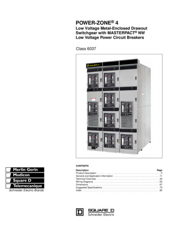
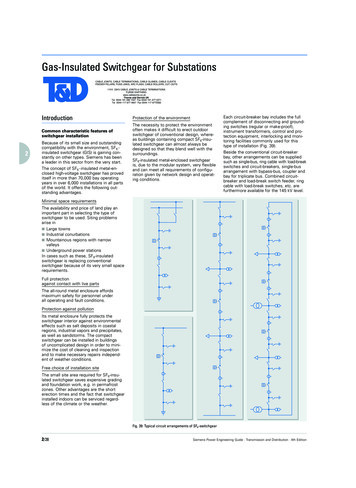
ELECTRIC POWER SYSTEMElectricity is generated at a power plant (1),voltage is “stepped-up” for transmission(2)Energy travels along a transmission line to the area where the power is needed(3)voltage is decreased or “stepped-down,” at another substation (4),& a distribution power line (5)carries that electricity until it reaches a home or business (6).
SINGLE LINE DIAGRAM
UNIT 1 – INTRODUCTION - SYLLABUS Importance of protective schemes for electricalapparatus and power system.Qualitative review of faults and fault currents.Relay terminology–definitions.Essential qualities of protection.Protection against over voltages due to lightningand switching-arcing grounds.Peterson Coil.Ground wires.Surge absorber and diverters.Power System Earthing–neutral Earthing.Basic ideas of insulation coordination.
IMPORTANCE OFPROTECTIVE SCHEMES FORELECTRICAL APPARATUSAND POWER SYSTEM
PROTECTION SYMBOL
PRIMARY EQUIPMENT & COMPONENTS Transformers-to step up or step down voltage level.Breakers-to energize equipment and interrupt faultcurrent to isolate faulted equipment.Insulators-to insulate equipment from ground andother phases.Isolators (switches) -to create a visible andpermanent isolation of primary equipment formaintenance purposes and route power flow overcertain buses.Bus-to allow multiple connections (feeders) to thesame source of power (transformer).
PRIMARY EQUIPMENT & COMPONENTS Grounding-to operate and maintain equipment safelyArrester-to protect primary equipment of suddenovervoltage (lightning strike).Switchgear–integrated components to switch,protect, meter and control power flow.Reactors-to limit fault current (series) or compensatefor charge current (shunt).VT and CT -to measure primary current and voltageand supply scaled down values to P&C, metering,SCADA, etc.Regulators-voltage, current, VAR, phase angle, etc.
WHY A SYSTEM NEEDS PROTECTION? Thereis no „fault free‟system. Ensure safety of personnel. Usually faults are caused bybreakdown of insulation dueto various reasons : systemover current, over voltage,lighting etc.
POWER SYSTEM WITHOUTPROTECTIONShort circuits and otherabnormal conditions oftenoccur on the power system.The heavy current associatedwith short circuits is likely tocausedamagetotheequipment.
ELEMENT OF PROTECTIONSYSTEM(1) Current and VoltageTransformers.(2) Relays.(3) Circuit breakers.(4) Batteries.(5) Fuses.(6) Lighting Arresters.
CURRENT TRANSFORMERCurrent transformer consists at least of two secondarywindings. The first winding is usually designed for measuring,the second is used for protection. The secondary of current transformers are almostconnected in star
VOLTAGE TRANSFORMER Voltagetransformer is often consists of twowindings. The first winding is connected in star, and thestare point must be earthed. The second winding is connected as open delta.
PURPOSE OF RELAYIsolate controlling circuit fromcontrolled circuit. Control high voltage systemwith low voltage. Control high current systemwith low current. Logic Functions
ADVANTAGES FOR USING PROTECTIVERELAYS Detectsystem failures whenthey occur and isolate thefaultedsectionfromtheremaining of the system. Mitigating the effects of failuresafter they occur. Minimize risk of fire, danger topersonal and other high voltagesystems.
CIRCUIT BREAKER Lowvoltage circuitbreaker. Magnetic circuit breaker. Medium voltage circuitbreaker. High voltage circuitbreaker.
BATTERY BANK Battery bank are called asbackbone of protectionsystem.Emergency use for powersystem.
FUSE Fuses are selected to allowpassage of normal currentand of excessive current onlyfor short periods.It is used to protect the lowvoltage or current ratingdevices.
LIGHTING ARRESTER Alightning arrester is adevice used on electricalpower system to protect theinsulation damaging effect oflightning. Alllighting arrester areearthed.
WHAT IS SWITCHGEAR ?Switchgear is thecombination of switches,fuses or circuit breakers(CB)used to control, protect &isolate electrical equipment. It is used de-energizeequipment & clear faults.
DIFFERENT ELEMENTS OF SWITCHGEAR
FUNCTION WISE CATEGORIESAutomatic & Manual operation{ example: Circuit breaker ,MCB ,MCCB } Only automatic operationFuseOnly manually activated / operatedIsolator, LBS
VOLTAGE WISE SWITCHGEAR CATEGORIES Low voltage Switchgearup to 11KVMedium voltage switchgearup to 66KVHigh Voltage switchgearup to 400KVExtra High Voltage switchgearup to 765KVHVDC Switch gear
QUALITATIVEREVIEW OF FAULTS& FAULT CURRENTS
NATURE & CAUSES OF FAULTS Insulation failure. Conducting path failure. Overvoltages due to lightening orswitching surges. Puncturing or breaking of insulators. Failure of conducting path due to brokenconductors. Failure of solid insulation due to aging, heat,moisture, overvoltage , accidental contactwith earth or earth screens, flash overvoltages and etc.,
FAULT IN POWER SYSTEM A power system fault may be defined as any conditionor abnormality of the system which involves theelectrical failure of primary equipment such asgenerators, transformers, bus bars, overhead lines andcables and all other items of plant which operate atpower system voltage.Electrical failure generally implies one or the other (orboth) of two types of failure, namely insulation failureresulting in a short- circuit condition or conductingpath failure resulting in an open-circuit condition, theformer being by far the more common type of failure.
FAULT IN POWER SYSTEM Symmetrical faultFaults giving rise to equal currents in linesdisplaced by equal phase angles i.e120oin threephase systems.Example: short circuit of all three phaseconductors of a cable at a single locationUnsymmetrical faultFaults in which not all the line currents are equaland not all have the same phase.Example(any one): single phase line to groundfault (L-G), two phase to ground (LL-G) fault andphase to phase (L-L) fault.
ABNORMALITIES IN POWER SYSTEMS Overcurrent (overload, short circuit, open circuit)Ground Potential (ungrounded equipment, touchpotentials, step potentials)Surge Voltages (lightning strokes, switchingsurges, harmonics)
FAULT TYPES (SHUNT)
FREQUENCY OF TYPES OF FAULTSType of Fault% OccurrenceSLGLLDLG3L85852 or less
FREQUENCY OF FAULT OCCURRENCEEquipment% 0f TotalOverhead linesCablesSwitch gearTransformersCTs and PTsControl EquipmentMiscellaneous50101512238
SYMMETRICAL FAULTTHREE-PHASE FAULTTHREE PHASE -EARTH FAULT
UNSYMMETRICAL FAULTPHASE –PHASE FAULTTWO PHASE –EARTH FAULTSINGLE PHASE -EARTH FAULT
OPEN CIRCUIT FAULTSINGLE-PHASE OPEN CIRCUITTWO-PHASE OPEN CIRCUITTHREE-PHASE OPEN CIRCUIT
Equipments&% of total faultOver head lines(50%)Under ground Cable(9%)Alternator(7%)Causes of FaultsLighting StrokeEarthquakeIcingBirdsTree branchesKite StringsInternal OvervoltageDamage due to diggingInsulation failure due totemperature rise Failure of Joints Stator & Rotor faults
Equipments&% of total faultTransformer(10%)Current Transformer&PotentialTransformer(12%)Switch Gear(12%)Causes of Faults Insulation Failure Faults in tap changer Overloading OvervoltageInsulation FailureBreak of ConductorsWrong Connections Insulation failure Leakage of air/oil/gas Mechanical defect
FAULT MINIMIZATION Improvingthe quality of machines,equipments,installationetc.,byimproving the design techniques. Adequate& reliable protectionsystem control. Regularmaintenance by trainedprofessionals. Effective management of electricalplant.
MERITS OF FAST FAULT CLEARING Helpsto avoid permanent damageto equipment & components ofthe apparatus. Reduces the chances of risks likefire hazards. Maintains the continuity of thepower supply. Brings back the power system to thenormal state sooner.
RELAY TERMINOLOGY –DEFINITIONS
WHAT ARE RELAYS?Relays are electrical switchesthat open or close another circuitunder certain conditions.
WHAT IS A PROTECTIVERELAY? Protectiverelays are deviceswhichmonitorpowersystemconditions and operate to quicklyand accurately isolate faults ordangerousconditions.Awelldesigned protective system can limitdamage to equipment, as well asminimize the extent of associatedservice interruption.
RELAY PURPOSE Isolatecontrolling circuit fromcontrolled circuit. Control high voltage systemwith low voltage. Control high current systemwith low current. Logic Functions.
RELAY TYPES Electromagnetic Relays (EMRs)Solid-state Relays (SSRs)There is no mechanical contacts to switchthe circuit.Microprocessor Based RelaysCommonly used in power systemmonitoring and protection.
ADVANTAGES /DISADVANTAGES Electromagnetic Relays (EMRs)–– Solid-state Relays (SSRs)–– SimplicityNot expensiveNo Mechanical movementsFaster than EMRMicroprocessor-based Relay–––Much higher precision and more reliable and durable.Capable of both digital and analog I/O.Higher cost
ADVANTAGES FOR USINGPROTECTIVE RELAYS Detectsystem failures when theyoccur and isolate the faulted sectionfrom the remaining of the system. Mitigatingthe effects of failuresafter they occur. Minimize risk offire, danger to personal and otherhigh voltage systems.
HOW A RELAY WORKS?
COMPONENTS OF POWER SYSTEMPROTECTION
Primary Relay : relay connected directly in thecircuit. Secondary Relay : relay connected to the protectedcircuit through CT & VT. Auxiliary Relay : relay operate in response toopening or closing of another relay. Measuring Relay : It performs the measurement ofnormal & abnormal conditions in the power system. Electro Magnetic Relay : It operates on theprinciple of Electro magnetic induction. Static Relay (Solid-state relay) : They use diode,transistors, SCRs, Logic gates etc.(Static circuit is the measuring circuit & nomoving parts) Microprocessor Based Relay : All functions of arelay can done by using microprocessor. Relays are
Thermal Relay : It operates on the principle of Electro-thermaleffect.Distance Relay : relay measures the impedance or reactance oradmittance.Impedance Relay : relay measures the impedance of thetransmission line.Reactance Relay : relay measures the reactance of thetransmission line.Over-current Relay : relay operates when the current exceeds apre-set value.Under-voltage Relay : relay operates when the voltage falls apre-set value.Directional Relay : relay able to sense whether fault lies inforward or reverse direction.Polarized Relay : relay depends on the direction of the current.
Differential Relay: it measures the difference b/w 2actual quantities.Earth fault Relay: It is used for protection of elementof a power system against Earth faults.Phase fault Relay: It is used for protection ofelement of a power system against phase faults.Negative Sequence Relay: relay uses negativesequence current as its actuating quantity.Zero Sequence Relay: relay uses zero sequencecurrent as its actuating quantity.
ESSENTIAL QUALITIES OF PROTECTIONORREQUIREMENT OF PROTECTIVE SYSTEM
Reliability - assurance that the protection will performcorrectly.Selectivity - maximum continuity of service withminimum system disconnection.Sensitivity - To detect even the smallest fault, current orsystem abnormalities and operate correctly at its setting.Speed - minimum fault duration and consequentequipment damage and system instability.Simplicity - minimum protective equipment andassociated circuitry to achieve the protection objectives.
ReliabilityThe level of assurance that the relaywill function as intended.o Reliability denotes :oDependability-certainty of correct operation– Security-assurance against incorrect operationSensitivity– Relaying equipment must besufficiently sensitive so that it willoperate when requiredo Must discriminate normal fromabnormal conditions.o
SelectivityPerformance of protective devices to select between thoseconditions for which prompt operation and those for which nooperation, or time delay operation is required.o Isolate faulted circuit resulting in minimum interruptions.o Implemented through “Zone of Protection”o SpeedooRemove a fault from the power system as quickly as possibleClassification:Instantaneous -no intentional delay– High Speed -less than 3 cycles– Time-Delay -intentional time delay–
POWER SYSTEMEARTHING NeutralEarthing /Grounding Peterson ArcingcoilGrounds
EARTHING / GROUNDING The process of connecting the metallic frame (i.e.non-current carrying part) of electrical equipment orsome electrical part of the system to earth (i.e. soil)is called grounding or earthing.Grounding or earthing may be classified as:(i) Equipment grounding(ii) System grounding
GROUNDING TYPESEquipment GroundingThe process of connecting noncurrent-carrying metal parts of theelectrical equipment to earth. System GroundingThe process of connecting someelectrical part of the power system toearth (i.e.soil) is called systemgrounding.
NEUTRAL EARTHING
NEUTRAL GROUNDINGConnecting neutral point to earth (i.e.soil) eitherdirectly or some circuit element(e.g.resistance, reactance, Peterson coil etc.)is called neutral grounding. Neutral grounding provides protection to equipment.(during earth fault, the current path is completedneutral)
ADVANTAGES OF NEUTRAL GROUNDING(i) Voltages of the healthy phases do not exceed line to groundvoltages i.e. they remain nearly constant.(ii) The high voltages due to arcing grounds are eliminated.(iii) Life of insulation is long.(iv) The over voltages is reduced.(v) It provides greater safety to personnel and equipment.(vi) It provides improved service reliability.(vii) Operating and maintenance expenditures are reduced.
METHODS OF NEUTRAL GROUNDING1. Solid or effective grounding2. Resistance grounding3. Reactance grounding4. Peterson-coil grounding5. Voltage transformer earthing
1. SOLID OR EFFECTIVE GROUNDING
1. SOLID OR EFFECTIVE GROUNDING When the neutral point of a 3-phase system is directlyconnected to earth(i.e. soil) is called solid groundingor effective grounding.When an earth fault occurs between earth and any onephase , the voltage to earth of the faulty phasebecomes zero, but the healthy phases remains atnormal phase values.Fault current(IF) completely nullified by capacitivecurrent(IC)
2. RESISTANCE GROUNDINGWhen the neutral point of a 3-phase system(e.g. 3-phase generator, 3-phase transformeretc.) is connected to earth ( i.e. soil) througha resistor, it is called resistance grounding.
2. RESISTANCE GROUNDINGAdvantages: By adjusting the value of R, the arcing grounds can be minimized. It improves the stability. Less interference. Minimize hazards.Disadvantages: By adjusting the value of R, the arcing grounds can be minimized. It improves the stability. Less interference. Minimize hazards.
3. REACTANCE GROUNDINGIn this system, a reactance is inserted between the neutraland ground.The purpose of reactance is to limit the earth fault current.Disadvantages:(i) In this system, the fault current required to operate theprotective device is higher than that of resistancegrounding for the same fault conditions.(ii) High transient voltages appear under fault conditions.
4. PETERSON COIL(OR)ARC SUSPENSION COILGROUNDING(OR)RESONANT GROUNDING
4. PETERSON COIL GROUNDINGIf inductance L of appropriate value is connected inparallel with the capacitance of the system, the fault currentIF flowing through L will be in phase opposition to thecapacitive current IC of the system. If L is so adjusted thatIL ICthen resultant current in the fault will be zero. Thiscondition is known as Resonant Grounding.When the value of L of arc suppression coil is suchthat the fault current IF exactly balances the capacitivecurrent IC, it is called Resonant Grounding.
4. PETERSON COIL GROUNDING An arc suppression coil (also called Peterson coil) is an ironcored coil connected between the neutral and earth. The reactor is provided with tappings to change theinductance of the coil. By adjusting the tappings on the coil, the coil can be tunedwith the capacitance of the system i.e. resonant groundingcan be achieved.
4. PETERSON COIL GROUNDING Suppose line to ground fault occurs in the line Bat point F. The fault current IF and capacitivecurrents IR and IY will flow as shown in FigNote that IF flows through the Peterson coil (orArc suppression coil) to neutral and backthrough the fault. The total capacitive currentIC is the phasor sum of IR & IY as shown inphasor diagram in Fig.The voltage of the faulty phase is applied acrossthe arc suppression coil. Therefore, fault currentIF lags the faulty phase voltage by 90 .The current IF is in phase opposition tocapacitive current IC [SeeFig]. By adjusting thetappings on the Peterson coil, the resultantcurrent in the fault can be reduced. Ifinductance of the coil is so adjusted that IL
4. PETERSON COIL GROUNDING
4. PETERSON COIL GROUNDING
5. VOLTAGE TRANSFORMER EARTHINGIn this method of neutral earthing, the primary of asingle-phase voltage transformer is connected betweenthe neutral and the earth as shown in Fig A low resistor in series with a relay is connected acrossthe secondary of the voltage transformer. The voltagetransformer provides a high reactance in the neutralearthing circuit and operates virtually as anungrounded neutral system.
5. VOLTAGE TRANSFORMER EARTHING
PROTECTION AGAINSTOVER VOLTAGES DUETO LIGHTNING ANDSWITCHING
PROTECTION AGAINST OVER VOLTAGES DUETO LIGHTNING AND SWITCHING During Operation , PS equipments such as Generator,transformer, Tx. lines may subject to Over Voltage.OV occurs due to Lightning, opening of CB & so on. Causes Of OV Internal CauseExternal Cause
PROTECTION AGAINST OVER VOLTAGES DUETO LIGHTNING AND SWITCHINGExternalLightning– Tree falls on Tx.lines causes SC–InternalInsulation Failure– Resonance– Arching Ground– Switching Surges–
TYPES OF OVER VOLTAGES PowerFrequency OV SwitchingOV LightningOV
1. POWER FREQUENCY OVDoes not have damaging effects like switching orlightning surges It will be harmful, if sustained for longer duration Mainly due to Groundfaults Sudden load rejection Loose connection
2. SWITCHING OV Also known as Switching surge or over voltage transient. Sudden rise of voltage for a very short duration in PS network isknown as transient voltage or voltage surge. An electrical transient appears, if there is sudden change in the stateof energy in PS network. This sudden change is due toi. Closing a Switchii. Opening a Switchiii. Occurrence of fault in system To control the switching OV , Resistor is inserted between thecontacts while switching off the circuit.
3. LIGHTNING OV Lightning is an electric discharge between cloud & Earthor between clouds.It is basically a huge spark.A large number of discharge occurs between or with inclouds than to earth & enough of them terminate on theearth causing serious hazards.Following actions of the lightning stroke generatetransients:* Direct Stroke to Phase Conductor* Stroke to earth very close to line
SURGEDIVERTER
WHAT IS SURGE? Surges disturbances on a powerwaveform that can damage, ordestroy equipment within anyhome, commercial building, ormanufacturing facility.Surgesaremicroseconds.measuredin
SURGE DIVERTERS A surge diverter is a piece ofequipment that diverts excessvoltagestoearth,thusprotecting sensitive electricaland electronic equipment.The surge diverter is normallyinstalledinthemainswitchboard.
REQUIREMENT OF SURGEDIVERTER It should not pass any current at normal and abnormalpower frequency voltage.It should breakdown as quickly as possible after theabnormal high frequency voltage arrives.It should not only protect the equipment for which it isused but should discharge current without damagingitself.It should interrupt power frequency follow currentafter the surge is discharge to ground.
TYPES OF SURGEDIVERTERS Rodgap type surge diverter. Protectortube or expulsiontype surge diverter. Valvetype surge diverter.
1. ROD GAP TYPE SURGEDIVERTER It is a very simple type of diverter andconsists of two 1.5 cm rods.One rod is connected to the line circuitand the other rod is connected to earth.The distance between gap and insulatormust not be less than one third of thegap length so that the arc may not reachthe insulator and damage it.The rod gap should be so set that itbreaks down to a voltage not less than30% below the voltage withstand level ofthe equipment to be protected.
ROD GAP TYPE SURGE DIVERTER
ROD GAP TYPE SURGE DIVERTER The string of insulators for an overhead line on thebushing of transformer has frequently a rod gap acrossit.Under normal operating conditions, the gap remainsnon-conducting.On the occurrence of a high voltage surge on the line,the gap sparks over and the surge current is conductedto earth.In this way excess charge on the line due to the surgeis harmlessly conducted to earth.
ROD GAP TYPE SURGE DIVERTERLimitations : After the surge is over, the arc in the gap is maintained bythe normal supply voltage, leading to short-circuit on thesystem. The rods may melt or get damaged due to excessive heatproduced by the arc. The climatic conditions (e.g. rain, humidity, temperatureetc.) affect the performance of rod gap arrester. The polarity of the surge also affects the performance ofthis arrester.
2. EXPULSION TYPE SURGE DIVERTERThis type of arrester is also called „protector tube‟and is commonly used on system operating at voltagesup to 33kV. It essentially consists of a rod gap in series with asecond gap enclosed within the fiber tube. The gap in the fiber tube is formed by two electrodes. The upper electrode is connected to rod gap and thelower electrode to the earth.
EXPULSION TYPE SURGE DIVERTER
EXPULSION TYPE SURGE DIVERTER The series gap is set to arc over at a specified voltage lowerthan the withstand voltage of the equipment to beprotected.The follow-on current is confined to the space inside therelatively small fibre tube.Part of the tube material vaporizes, and the high pressuregases so formed are expelled through the vent at the lowerend of the tube, causing the power follow-in arc to beextinguished.The device, therefore, has the desired self-clearing property.
EXPULSION TYPE SURGE DIVERTERAdvantages They are not very expensive. They can be easily installed.They are improved form of rod gap arresters as theyblock the flow of power frequency follow currents.
EXPULSION TYPE SURGE DIVERTERLimitations An expulsion type arrester can perform only limitednumber of operations as during each operation some of thefiber material is used up. This type of arrester cannot be mounted on enclosedequipment due to discharge of gases during operation. Due to the poor volt/amp characteristic of the arrester, it isnot suitable for protection of expensive equipment.
3. VALVE TYPE SURGE DIVERTER Valve type arresters incorporate nonlinear resistors and are extensively used onsystems, operating at high voltages.It consists of two assemblies (i) series sparkgaps and (ii) non-linear resistor discsThe non-linear elements are connected inseries with the spark gaps. Both theassemblies are accommodated in tightporcelain container.The spark gap is a multiple assemblyconsisting of a number of identical sparkgaps in series.Each gap consists of two electrodes withfixed gap spacing.
VALVE TYPE SURGE DIVERTER The spacing of the series gaps is such that it will withstandthe normal circuit voltage.An over voltage will cause the gap to break down causingthe surge current to ground via the non-linear resistors.The non-linear resistor discs are made of inorganiccompound such as thyrite or metrosil.These discs are connected in series.The non-linear resistors have the property of offering a highresistance to current flow when normal system voltage isapplied, but a low resistance to the flow of high surgecurrents.
VALVE TYPE SURGE DIVERTERWhen the surge is over the non linear resistor assumehigh resistance to stop the flow of current.
VALVE TYPE SURGE DIVERTER Under normal conditions, the normal system voltage isinsufficient to cause the breakdown of air gap assembly.On the occurrence of an over voltage, the breakdown of theseries spark gap takes place and the surge current isconducted to earth via the nonlinear resistances.Since the magnitude of surge current is very large, thenonlinear elements will offer a very low resistance to thepassage of surge.The surge will rapidly go to earth instead of being sent backover the line.
VALVE TYPE SURGE DIVERTERADVANTAGES : They provide very effective protection against surges. They operate very rapidly taking less than a second The impulse ratio is practically unity.
VALVE TYPE SURGE DIVERTERLimitations : They may fail to check the surge ofvery steep wave front reaching theterminal apparatus. This calls foradditional steps to check steep frontedwaves.Their performance is adverselyaffected by the entry of moisture intothe enclosure. This necessitateseffective sealing of the enclosure at alltimes.
SURGE ABSORBER
SURGE ABSORBER The Device which reduces the steepness of the wavefront of a particular surge & thus minimizes thedanger due to over voltage is known as surge absorber.Note:Surge Diverter : Diverts the Surge to earthSurge Absorber : Absorbs the Surge energy
TYPES OF SURGE ABSORBER Ferranti ERASurge absorberSurge absorber
FERRANTI SURGE ABSORBER Dissipater Air cored inductorIt consists of an air core inductorconnected Series inline & surroundedby an earth metallic sheet (ie)dissipater.Whenever a travelling wave isincident on the surge absorber, energyis transformed by mutualinductance between coil &dissipater. ie., the energycontained in the wave isdissipated in the form of heat.Because of the series inductance thesteepness of the wave is alsoreduced.
ERA SURGE ABSORBER Improved form of Surgeabsorber is the ElectricalResearch Association typesurge filter.G–Gap ; E–Expulsion gapWhen a wave reaches the L, ahigh voltage is induced acrossit causing the gap G to breakdown putting the R and E into circuit.Thus incoming wave getflattened by L & R and itsamplitude is reduced by E.
BASIC IDEAS OFINSULATION COORDINATION
INSULATION COORDINATION Correlating (link) apparatusinsulation with insulation of theprotective device to achieveoverall protection is known asinsulation coordination.The insulation strength ofvarious equipments should behigher than that of lightningarresters and other surgeprotective devices.
INSULATION COORDINATION In its simplest form,Insulation Coordination isthe selection of insulationstrength.Characteristics of lightningarrestor should be correlatedwith equipment isolation
INSULATION COORDINATION The insulation of theline lightning arrestor& equipment should becoordinated. Curve A relates toProtective device Curve B –equipmentto be protected Protective devicemust have insulationcharacteristics whichmust be lie below theinsulationcharacteristics ofinstrument to beprotected.
INSULATION COORDINATIONA perfect insulation coordination must satisfy thefollowing conditions: The insulation should withstand both operatingvoltage & voltage surges. The discharge of OV due to internal or external causesmust flow to ground efficiently. Only external flashover should cause breakdown.
BASIC IMPULSE INSULATION LEVEL (BIL) It is defined as “a reference level expressed inimpulse crest voltage with a standard wave notlonger than 1.5*40 micro seconds wave”.
THANK YOU
EE2402 - PROTECTION & SWITCHGEAR SYLLABUS. ELECTRIC POWER SYSTEM Electricity is generated at a power plant (1), voltage is “stepped-up” for transmission(2) Energy travels along a transmission line to the area where the power is needed (3) voltage i