Transcription
CatalogHA 40.2 ·Edition 2017Switchgear Type 8DJH for SecondaryDistribution Systems up to 24 kV,Gas-InsulatedMedium-Voltage Switchgearsiemens.com/8DJH
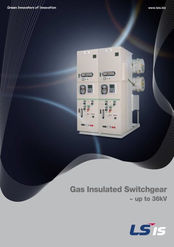
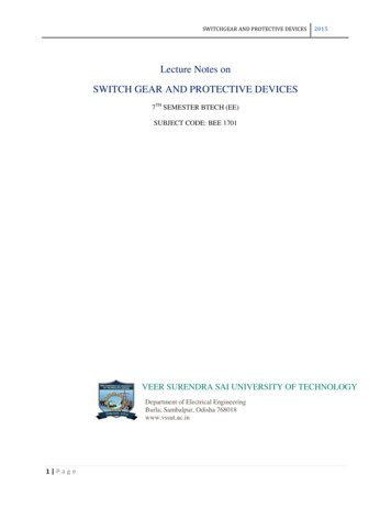
ApplicationR-HA40-112.tifR-HA40-111.tifTypical usesR-HA40-110.tifR-HA40-157 tifR HA40 160 tifR HA40-150a tifApplicationin publicand industrialenergy systems2Switchgear Type 8DJH for Secondary Distribution Systems up to 24 kV, Gas-Insulated · Siemens HA 40.2 · 2017
ContentsSwitchgear Type 8DJHfor SecondaryDistribution Systemsup to 24 kV,Gas-InsulatedApplicationPageTypes, typical uses, ratings, approvals4 and 5RequirementsFeatures, safety, technology, classification6 to 8Technical DataElectrical data of the switchgearSwitching capacity andclassification of switching devicesMedium-Voltage SwitchgearProduct RangeCatalog HA 40.2 · 2017Individual panels and modulesAir-insulated billing metering panelsProduct range overview of panel blocks910 and 1112 to 141516 and 17Invalid: Catalog HA 40.2 · 2014Designsiemens.com / medium-voltage-switchgearsiemens.com/ 8DJHPanel designOutdoor enclosureOperation18 to 212223ComponentsThree-position switch-disconnectorVacuum circuit-breakerBusbar extension, modularityHV HRC fuse assemblyAllocation of HV HRC fusesand transformer ratingsCurrent and voltage transformersCurrent and voltage sensorsCable connections, cable plugsInterlocks, locking devicesIndicating and measuring equipmentTransformer monitor system,time-fuse-link protection systemIntelligent transformer substationProtection systemsLow-voltage compartment, low-voltage niche24 to 2627 to 29303132 to 3637 to 4142 and 4344 to 505152 to 606162 and 636465DimensionsRoom planning, switchgear installationIndividual panels and modules,panel combinationsOutdoor enclosureFloor openings and fixing points66 to 6869 to 818283 to 86InstallationThe products and systems described in this catalogare manufactured and sold according to a certifiedmanagement system (acc. to ISO 9001, ISO 14001and BS OHSAS 18001).Shipping data, transport87 and 88StandardsStandards, specifications, guidelines89 to 91Switchgear Type 8DJH for Secondary Distribution Systems up to 24 kV, Gas-Insulated · Siemens HA 40.2 · 20173
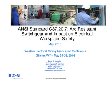
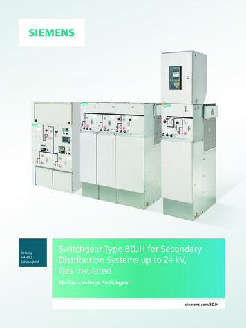
ApplicationIndividual circuit-breakerpanel 500 mm4RRT blockR-HA40-156.epsR-HA40-149b tifR-HA40-150a.epsTypes8DJH Compact RRT blockSwitchgear Type 8DJH for Secondary Distribution Systems up to 24 kV, Gas-Insulated · Siemens HA 40.2 · 2017
ApplicationTypical uses, ratings, approvals8DJH switchgear is a factory-assembled, type-tested,3-pole metal-enclosed single-busbar switchgear for indoorinstallation.8DJH switchgear is used in public and industrial energysystems of the secondary distribution level, e.g. in Local ring-main units, customer transfer substations andswitching substations of power supply and public utilities Wind power and solar plants, hydroelectric power plants Water and sewage treatment plants Airports, railway stations, underground railway stations Open-cast mining facilities High-rise buildings.Electrical data (maximum values) and dimensionsRated voltagekV7.2Rated frequencyHz50 / 60 50 / 60 50 / 60 50 / 60 50 / 60Rated short-durationpower-frequencywithstand voltagekV20 1)28 2)363850Rated lightning impulsewithstand voltagekV60 1)75 2)9595125Rated peakwithstand currentkA63 / 65 63 / 65 63 / 65 63 / 65 50 / 55Rated short-circuitmaking currentkA63 / 65 63 / 65 63 / 65 63 / 65 50 / 55Rated short-timewithstand current 3 skA20 / 21 20 / 21 20 / 21 20 / 21 20 / 21Rated short-timewithstand current 1 skA2525252520 / 21Rated normal currentof the busbarA630630630630630Rated normal currentof feedersA200 / 250 / 400 / 630 3)Width (feeders)mm310 / 430 / 500Depth– without pressurerelief duct– with pressurerelief ductmm775775775775775mm890890890890890mmoptionally 1040 / 1200 / 1400 / 1700Heightwithout low-voltagecompartment andpressure relief duct121517.5243)1) 32 kV / 60 kV according to some national requirements2) 42 kV / 75 kV according to some national requirements3) Depending on the feeder function and the selected design optionsNational approval GOSTBy certification in the system GOST R in Russia, 8DJHis approved for application at the voltage levels 6 kV,10 kV and 20 kV.The approval is valid in the countries Russia, Belarus,Kazakhstan and Ukraine.Switchgear Type 8DJH for Secondary Distribution Systems up to 24 kV, Gas-Insulated · Siemens HA 40.2 · 20175
RequirementsFeaturesSafetyEnvironmental independenceHermetically tight, welded switchgear vessels made ofstainless steel as well as single-pole solid insulation makethe parts of the primary circuit under high voltage of 8DJHswitchgear Insensitive to certain aggressive ambient conditions,such as:– Saline air– Air humidity– Dust– Condensation Tight to ingress of foreign objects, such as:– Dust– Pollution– Small animals– Humidity.Personal safety Safe-to-touch and hermetically sealed primary enclosure Standard degree of protection IP 65 for all high-voltageparts of the primary circuit, at least IP 2X for the switchgear enclosure according to IEC 60529 and VDE 0470-1 Cable terminations, busbars and voltage transformersare surrounded by earthed layers. All high-voltage partsincluding the cable terminations, busbars and voltagetransformers are metal-enclosed Operating mechanisms and auxiliary switches safelyaccessible outside the primary enclosure (switchgearvessel) High resistance to internal arcs by logical mechanicalinterlocks and tested switchgear enclosure Panels tested for resistance to internal faults up to 21 kA Capacitive voltage detecting system to verify safeisolation from supply Due to the system design, operation is only possiblewith closed switchgear enclosure Logical mechanical interlocks prevent maloperation HV HRC fuses and cable sealing ends are only accessiblewhen outgoing feeders are earthed Feeder earthing via make-proof earthing switches.Compact designThanks to the use of SF6 insulation, compact dimensionsare possible. Thus: Existing switchgear rooms and substation roomscan be used effectively New constructions cost little Costly city-area space is saved.Maintenance-free designSwitchgear vessels designed as sealed pressure systems,maintenance-free switching devices and enclosed cableplugs ensure: Maximum supply reliability Personnel safety Sealed-for-life design according to IEC 62271-200(sealed pressure system) Installation, operation, extension and replacementwithout SF6 gas work Reduced operating costs Cost-efficient investment No maintenance cycles.InnovationThe use of digital secondary systems and combined protection and control devices ensures: Clear integration in process control systems Flexible and highly simplified adaptation to new systemconditions and thus cost-efficient operation.Service lifeUnder normal operating conditions, the expected service lifeof gas-insulated switchgear 8DJH is at least 35 years, probably40 to 50 years, taking the tightness of the hermetically welded switchgear vessel into account. The service life is limited bythe maximum number of operating cycles of the switchgeardevices installed: For circuit-breakers, according to the endurance classdefined in IEC 62271-100 For three-position disconnectors and earthing switches,according to the endurance class defined in IEC 62271-102 For three-position switch-disconnectors and earthingswitches, according to the endurance class defined inIEC 62271-103.6Security of operation Hermetically sealed primary enclosure independent ofenvironmental effects (pollution, humidity and smallanimals) Welded switchgear vessels, sealed for life Maintenance-free in an indoor environment(IEC 62271-1 and VDE 0671-1) Operating mechanisms of switching devices accessibleoutside the primary enclosure (switchgear vessel) Metal-coated, plug-in inductive voltage transformersmounted outside the SF6 switchgear vessel Current transformers as ring-core current transformersmounted outside the SF6 switchgear vessel Complete switchgear interlocking system with logicalmechanical interlocks Mechanical position indicators integrated in the mimicdiagram Minimum fire load Option: Resistance against earthquakes.Reliability Type and routine-tested Standardized and manufactured using numericallycontrolled machines Quality assurance in accordance with DIN EN ISO 9001 More than 500,000 switchgear panels of Siemens inoperation worldwide for many years.Switchgear Type 8DJH for Secondary Distribution Systems up to 24 kV, Gas-Insulated · Siemens HA 40.2 · 2017
RequirementsTechnologyGeneral Three-pole primary enclosure, metal-enclosed Welded switchgear vessel without seals, made of stainless steel, with welded-in bushings for electrical connections and mechanical components Insulating gas SF6 (fluorinated greenhouse gas) Maintenance-free components under normal ambientconditions according to IEC 62271-1 and VDE 0671-1 Three-position switch-disconnector with load-breakfunction and make-proof earthing function Vacuum circuit-breaker Cable connection with outside-cone plug-in system– In ring-main and circuit-breaker feeders with boltedcontact (M16)– In transformer feeders with plug-in contact or optionallywith bolted contact (M16) Wall-standing or free-standing arrangement Pressure relief downwards, optionally to the rear orupwards via pressure absorber systems.Interlocks According to IEC 62271-200 and VDE 0671-200 Logical mechanical interlocks prevent maloperation Logical mechanical interlocks and the constructivefeatures of the three-position switches prevent maloperation as well as access to the cable connection ofthe feeders and HV HRC fuses under voltage Impermissible and undesired operations can be prevented by means of locking devices provided at the switchingdevices A detailed description of all interlocking options isavailable on page 51.Insulating system Switchgear vessel filled with SF6 gas Features of SF6 gas:– Non-toxic– Odorless and colorless– Non-inflammable– Chemically neutral– Heavier than air– Electronegative (high-quality insulator)– Global Warming Potential GWP 22,800 Pressure of SF6 gas in the switchgear vessel(absolute values at 20 C):– Rated filling level: 150 kPa– Design pressure: 180 kPa– Design temperature of the SF6 gas: 80 C– Operating pressure of bursting disc: 300 kPa– Bursting pressure: 550 kPa– Gas leakage rate: 0.1 % per year.Modular design Individual panels and panel blocks can be lined up andextended at will – without gas work on site Low-voltage compartment available in 4 overall heights,wiring to the panel via plug connectors.Panel design Factory-assembled, type-tested Metal-enclosed, with metallic partitions 1) Hermetically tight, welded switchgear vessel made ofstainless steel Maintenance-free Degree of protection– IP 65 for all high-voltage parts of the primary circuit inthe gas-insulated panels– IP 2X for the switchgear enclosure Vacuum circuit-breaker with three-position disconnectorfor disconnecting and earthing Three-position switch-disconnector Cable connection with outside-cone plug-in systemaccording to DIN EN 50181 Wall-standing arrangement, optionally free-standingarrangement Installation and possible later extension of existingpanels without gas work Replacement of instrument transformers without gaswork, as they are located outside the gas compartments Enclosure made of sendzimir-galvanized sheet steel,front cover powder-coated in color “light basic” (SN 700) Low-voltage compartment removable, plug-in bus wires Lateral, metallic wiring ducts for control cables.Instrument transformers Current transformers not subjected to dielectric stress Easy replacement of current transformers designed asring-core transformers Metal-coated, plug-in voltage transformers.Vacuum circuit-breaker Maintenance-free under normal ambient conditionsaccording to IEC 62271-1 and VDE 0671-1 No relubrication or readjustment Up to 10,000 operating cycles Vacuum-tight for life.Secondary systems Customary protection, measuring and control equipment Option: Numerical multifunction protection relay withintegrated protection, control, communication, operating and monitoring functions Can be integrated in process control systems.1) Corresponds to “metal-clad” according toformer standard IEC 60298Switchgear Type 8DJH for Secondary Distribution Systems up to 24 kV, Gas-Insulated · Siemens HA 40.2 · 20177
RequirementsClassification8DJH switchgear is classified according toIEC / EN 62271-200 / VDE 0671-200.Design and constructionPartition classLoss of service continuity categoryfor panels or panel blocks– With HV HRC fuses (T, H)– Without HV HRC fuses (R, L, .)Billing metering panel MCable panel KAccessibility to compartments(enclosure)– Busbar compartment– Switching-device compartment– Low-voltage compartment(option)– Cable compartment for panelsor panel blocks– With HV HRC fuses (T)– Without HV HRC fuses (R, L, .)– Only cable feeder (K)– Metering panels(air-insulated) (M)Internal arc classification (Option)PM (partition of metal)LSC 2LSC 2LSC 1– Non-accessible– Non-accessible– Tool-based– Interlock-controlled– Interlock-controlled– Tool-based– Tool-basedDesignation of the internal arcclassification IACIAC class for 8DJH Standard and8DJH Compact design for– Wall-standing arrangement– Free-standing arrangementAdditionally only for8DJH Compact design for– Installation in substationswithout control aisle 1)Rated voltage 7.2 kV to 24 kVType of accessibility ASwitchgear in closed electricalservice location, access“for authorized personnel only”(according to IEC / EN 62271-200)FrontLateralRear(for free-standing arrangement)–F–L–RIAC A FLIAC A FLRIAC A FArc test currentUp to 21 kATest duration1s1) Rear space required for pressure relief.Application recommended in prefabricated substations without control aisle, tested according to IEC 62271-202.8Switchgear Type 8DJH for Secondary Distribution Systems up to 24 kV, Gas-Insulated · Siemens HA 40.2 · 2017
Technical DataElectrical data of the switchgearRated insulation levelRated voltage UrkV 7.212Rated short-duration power-frequencywithstand voltage Ud– Phase-to-phase, phase-to-earth, open contact gap– Across the isolating distancekV 20kV 23Rated lightning impulse withstand voltage Up– Phase-to-phase, phase-to-earth, open contact gap– Across the isolating distancekV 60kV 7017.52428 / 42 1) 3632 / 48 1) 39384550607585951109511012514525252520/21 1)up to kA 6363636350/52.5 1)for ring-main feedersup to kA 6363636350/52.5 1)for circuit-breaker feedersup to kA 6363636350/52.5 1)for transformer feedersup to kA 6363636350/52.5 1)for switchgear with t k 1 sup to kA 2525252520/21 1)or switchgear with t k 3 s (design option)up to kA 20/21 1)up to kA 6565656552/55 1)for ring-main feedersup to kA 6565656552/55 1)for circuit-breaker feedersup to kA 6565656552/55 1)kA 6565656552/55 1)Rated frequency frHz 50 / 60Rated normal current Ir 2)50 Hz Rated short-timewithstand current Ikfor ring-main feedersA 400 or 630for busbarA 630for circuit-breaker feedersA 250 or 630for transformer feedersA 200 3)for switchgear with t k 1 sup to kA 25for switchgear with t k 3 s (design option)up to kA 20/21 1)Rated peak withstand current IpRated short-circuitmaking current Ima60 Hz Rated short-timewithstand current IkRated peak withstand current IpRated short-circuitmaking current Imafor transformer feedersFilling pressure(pressure values at 20 C)Minimum functional level pme (absolute)Ambient air temperature T 4)OperationRated filling level pre (absolute)Storage / transportDegree of protection15kPa 150standardkPa 130 C –25 to 55on request C –40 to 70standard C –25 to 55on request C –40 to 70for gas-filled switchgear vesselIP65for switchgear enclosureIP2X / IP3X 1)for low-voltage compartmentIP3X / IP4X 1)1) Design option2) The rated normal currents apply to ambient air temperatures of max. 40 C.The 24-hour mean value is max. 35 C (according to IEC / EN 62271-1 / VDE 0671-1)3) Depending on HV HRC fuse-link4) Minimum and maximum permissible ambient air temperature depending on the secondary equipment usedSwitchgear Type 8DJH for Secondary Distribution Systems up to 24 kV, Gas-Insulated · Siemens HA 40.2 · 20179
Technical DataSwitching capacity and classification of switching devicesThree-position switch-disconnectorSwitching capacity for general-purpose switches according to IEC / EN 62271-103 (former: IEC / EN 60265-1 / VDE 0670-301)kV 7.2Rated voltage Ur100 operations Iload [I1]Test dutyTDloadRated mainly active loadbreaking current IloadTest dutyTDloopRated closed-loop breaking current Iloop [I2a]A 630Test dutyTDccRated cable-charging breaking current Icc [I4a]A 68Test dutyTDlcRated line-charging breaking current Ilc [I4b]A 68Test dutyTDmaRated short-circuit making current ImaTest dutyTDef1Rated earth-fault breaking current Ief1 [I6a]A 200Test dutyTDef2Rated cable-charging breaking current and line-charging breakingcurrent under earth-fault conditionsIef2 [I6b ( 3 · I4a) or I6b ( 3 · I4b)]A 11520 operations 0.05 Iload [I1]121517.524A 630A 31.550 Hzup to kA 6363636350/52.5 1)60 Hzup to kA 6565656552/55 1)Number of operating cycles, mechanical / Classificationn 1000/M1Number of operating cycles, electrical with Iload / Classificationn 100/E3Number of short-circuit making operations with Ima / Classificationn 5 / E3C-classification for general-purpose switches (no restrikes, TD: Icc, Ilc)C25 / E35 / E35 / E35 / E3C2C2C2C2Switching capacity for make-proof earthing switch according to IEC / EN 62271-102 / VDE 0671-102Rated short-circuit making current Ima50 Hzup to kA 6363636350/52.5 1)60 Hzup to kA 6565656552/55 1)130013001300Number of operating cycles, mechanical / Classificationn 1000/M0Number of short-circuit making operationsn 5ClassificationE2Switch-disconnector / fuse combinationSwitching capacity for switch-disconnector / fuse combination according to IEC / EN 62271-105 / VDE 0671-105Rated normal currentA 200 2)Rated transfer current ItransferA 15001500Switching capacity for make-proof earthing switch, feeder side, in transformer feeder with HV HRC fusesRated short-circuit making current ImaRated short-time withstand current Ik with t k 1 s50 HzkA 6.360 HzkA 6.5kA 2.51) Design option2) Depending on HV HRC fuse-link10Switchgear Type 8DJH for Secondary Distribution Systems up to 24 kV, Gas-Insulated · Siemens HA 40.2 · 2017
Technical DataSwitching capacity and classification of switching devicesVacuum circuit-breakerSwitching capacity according to IEC / EN 62271-100 / VDE 0671-100Type 1.1 with three-position disconnectorkV 7.2Rated voltage UrRated normal current of feeders Ir50 Hz Rated short-timewithstand current Ik121517.52425252520/21 1)A 630for switchgear with t k 1 sfor switchgear with t k 3 sup to kA 25up to kA 20/21 1)Rated peak withstand current Ipup to kA 6363636350/52.5 1)Rated short-circuit breaking current Iscup to kA 2525252520/21 1)Rated short-circuit making current Imaup to kA 6363636350/52.5 1)for switchgear with t k 1 sup to kA 2525252520/21 1)for switchgear with t k 3 sup to kA 20/21 1)60 Hz Rated short-timewithstand current IkRated peak withstand current Ipup to kA 6565656552/55 1)Rated short-circuit breaking current Iscup to kA 2525252520/21 1)Rated short-circuit making current Imaup to kA 6565656552/55 1)Number of mechanical operating cycles for disconnectorn 1000Number of mechanical operating cycles for earthing switchn 1000Number of mechanical operating cycles for circuit-breakern 10,000Classification of circuit-breakerM2, E2, C2, S2Classification of disconnectorM0Classification of make-proof earthing switchE2Rated operating sequenceO – 0.3 s – CO – 3 min – COO – 0.3 s – CO – 15 s – CO on requestNumber of short-circuit breaking operationsn 25 or 50Type 2 with three-position disconnectorkV 7.2Rated voltage UrRated normal current of feeders Ir121517.524A 250 A or 630 Aup to kA 25up to kA 20/21 1)25252520/21 1)Rated peak withstand current Ipup to kA 6363636350/52.5 1)Rated short-circuit breaking current Iscup to kA 2525252520/21 1)Rated short-circuit making current Ima50 Hz Rated short-timewithstand current Ikfor switchgear with t k 1 sfor switchgear with t k 3 s60 Hz Rated short-timewithstand current Ikup to kA 6363636350/52.5 1)for switchgear with t k 1 sup to kA 2525252520/21 1)for switchgear with t k 3 sup to kA 20/21 1)Rated peak withstand current Ipup to kA 6565656552/55 1)Rated short-circuit breaking current Iscup to kA 2525252520/21 1)Rated short-circuit making current Imaup to kA 6565656552/55 1)Number of mechanical operating cycles for disconnectorn 1000Number of mechanical operating cycles for earthing switchn 1000Number of mechanical operating cycles for circuit-breakern 2000Classification of circuit-breakerM1, E2, C1, S1Classification of disconnectorM0Classification of make-proof earthing switchE2Rated operating sequenceO – 3 min – CO – 3 min – CONumber of short-circuit breaking operationsn 6 or 201) Design optionSwitchgear Type 8DJH for Secondary Distribution Systems up to 24 kV, Gas-Insulated · Siemens HA 40.2 · 201711
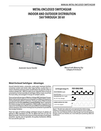
Product RangeIndividual panels and modules – freely configurable for up to 4 functions in the blockCable feeder2)Type K310 mm wide1)HA40-2291 epsHA40-2125a epsCable feeder1)Type K(E) 2)430 mm widewith make-proofearthing sconnectorThree-positiondisconnectorCapacitive voltagedetecting systemHV HRC fuse1)Circuit-breaker feederType R310 mm wideHA40-2127a epsHA40-2124a epsRing-main feeder1)Type L430 mm wideCable-type currenttransformerCable connectionwith outside cone(not included in thescope of supply)Surge arresteror limiterMake-proofearthing switchHA40-2126a epsTransformer feeder1)Type T430 mm wide1) Only for endpanel, on the freeconnection side ofthe busbar2) Only as individualpanel and in2-panel blocks12Switchgear Type 8DJH for Secondary Distribution Systems up to 24 kV, Gas-Insulated · Siemens HA 40.2 · 2017
Product RangeIndividual panelsBus sectionalizer panelHA40-2128 epsType S 1)430 mm widewith switch-fuse combinationType H 1)430 mm wideHA40-2129a epswith apacitive voltagedetecting systemHA40-2130 epsType S(620)(earthing on the left)620 mm wideHA40-2131c epsBus sectionalizer panel with switch-disconnector4MT3Type S(500)with currenttransformer500 mm wideHV HRC fuseCurrent transformerPlug-in voltagetransformer 4MT3HA40-2132 epsType V (with circuitbreaker 1.1 or 2)500 mm wide4MT3HA40-2133b epsBus sectionalizer panel with circuit-breakerDesign option withcurrent transformer4MT31) Also executable as right-hand panel in panel blocksSwitchgear Type 8DJH for Secondary Distribution Systems up to 24 kV, Gas-Insulated · Siemens HA 40.2 · 201713
Product RangeIndividual panelsCircuit-breaker feederType R(500)500 mm wide1)4MT3HA40-2135b epsHA40-2134c epsRing-main feederType L(500)with circuitbreakertype 1.1 or4MT3type 2)500 mm wide1)*)Three-positionswitch-disconnector*)4MC63 .Vacuumcircuit-breaker4MC63 .Three-positiondisconnectorCapacitive voltagedetecting system4MT84MT8*)Three-phasecurrent transformerHA40-2137c epsType M(500)500 mm wide1)Busbar voltage metering panel,fused on the primary sideHA40-2274b epsBusbar voltage metering panelType M(430)430 mm wideCable-type currenttransformer1)Cable connectionwith outside cone(not included in thescope of supply)Surge arresteror limiter4MT34MT3Plug-in voltagetransformerType E310 mm wide1)Busbar earthing panelHA40-2138a epsHA40-2136a epsBusbar earthing panelType E(500)500 mm wide1)4MT31) Only for endpanel, on thefree connectionside of the busbar14Switchgear Type 8DJH for Secondary Distribution Systems up to 24 kV, Gas-Insulated · Siemens HA 40.2 · 2017
Product RangeAir-insulated billing metering panels type M, 840 mm wideBilling metering panels with cable connection on the leftHA40-2139a epsCurrent transformer,cast-resin insulatedP1P2P2P1Voltage transformer,cast-resin insulatedP1P2P2P1Capacitive voltagedetecting systemFixed earthingpoints forbusbar earthingBilling metering panels with cable connection on the rightHA40-2140a epsP1 and P2are terminaldesignations ofthe currenttransformerP1P2P2P1P1P2P2P1HA40-2141a epsBilling metering panels with busbar connection on both sidesP1P2P2P1P1P2P2P1Billing metering panels with cable connection on both sidesP2P2P1P1P2P2P1HA40-2142a epsP1Switchgear Type 8DJH for Secondary Distribution Systems up to 24 kV, Gas-Insulated · Siemens HA 40.2 · 201715
Product RangeProduct range overview of panel blocks (excerpt)Panel blockComponents shown in dotted linescan be used optionally.WidthDepthHeightmmmmmmPanel blockComponents shown in dotted linescan be used optionally.Installation dimensionsWidthDepthHeightmmmmmmKTKLHA40-2111b epsRRRTHA40-2112b epsTRRT1 transformer feeder,1 radial cable connectionwith make-proof earthingswitch8607751200140017001 ring-main feeder,1 transformer feeder74077510401200140017002 ring-main feeders,1 transformer feeder105077510401200140017003 ring-main feeders,1 transformer feeder13607751200140017002 ring-main feeders,2 transformer feeders1480775120014001700K(E)LK Radial cableconnection asincomingfeeder1 circuit-breaker feeder,1 radial cable connection740775RLRRLRRRLLRRLSwitchgear Type 8DJH for Secondary Distribution Systems up to 24 kV, Gas-Insulated · Siemens HA 40.2 · 20171200140017001 circuit-breaker feeder,1 radial cable connectionwith make-proof earthingswitch860775HA40-2219a eps120014001700HA40-2114a eps775HA40-2115a epsHA40-2110b epsRRT740K Radial cableconnection asincomingfeederHA40-2116a epsHA40-2218a epsHA40-2109b epsRTK Radial cableconnection asincomingfeeder1 transformer feeder,1 radial cable connectionHA40-2117a epsK Radial cableconnection asincomingfeederHA40-2113a epsPanel blocks with circuit-breaker feeders,optionally with busbar extensionHA40-2108b epsPanel blocks with transformer feeders,optionally with busbar extensionK(E)T16Installation dimensions1200140017001 ring-main feeder,1 circuit-breaker feeder7407751200140017002 ring-main feeders,1 circuit-breaker feeder10507751200140017003 ring-main feeders,1 circuit-breaker feeder13607751200140017002 ring-main feeders,2 circuit-breaker feeders1480775120014001700
Product RangeProduct range overview of panel blocks (excerpt)Panel blockComponents shown in dotted linescan be used optionally.Installation dimensionsWidthDepthHeightmmmmmmPanel blockComponents shown in dotted linescan be used optionally.Installation dimensionsWidthDepthHeightmmmmmmPanel blocks with transformer feeders,optionally with busbar a eps3 ring-main feeders930RRRR7751040120014001700HA40-2122b epsHA40-2118a eps2 ring-main feedersHA40-2121b epsPanel blocks with ring-main feeders,optionally with busbar extension2 transformer feeders8607751200140017003 transformer feeders1290775120014001700HA40-2120a eps4 ring-main feeders1240775120014001700Panel blockComponents shown in dotted linescan be used optionally.Installation 361a epsRRT-RHA40-2362a epsRRTHA40-2360a epsPanel blocks with transformer feeders as 8DJH Compact, without busbar r Type 8DJH for Secondary Distribution Systems up to 24 kV, Gas-Insulated · Siemens HA 40.2 · 201717
DesignPanel design (examples)Ring-main feederTransformer feederType RType TSectionSection5261HA40-2144e epsHA40-2143c eps52617733844991112131010Circuit-breaker feederType LSectionHA40-2145e eps52611 Control board (for details, see page 23)2 Busbar arrangement13 Three-position switch-disconnector4 Pressure relief device1514845 Wiring duct, removable, for protectionand / or bus wires6 Switchgear vessel, filled with gas7 Operating mechanism of switching device98 Bushing for cable plug with bolted contact(M16)9 Cable compartment cover10 Earthing busbar with earthing connection(design option)11 Partition12 HV HRC fuse assembly13 Bushing for cable plug with plug-in contact,optionally bolted contact (M16)Type 1.118Type 210 14 Vacuum circuit-breaker15 Circuit-breaker operating mechanism,operating mechanism for three-positiondisconnectorSwitchgear Type 8DJH for Secondary Distribution Systems up to 24 kV, Gas-Insulated · Siemens HA 40.2 · 2017
DesignPanel design (examples)Circuit-breaker feederType L(500)SectionHA40-2146d eps1 Control board (for details, see page 23)2 Option: Low-voltage compartment3 Busbar arrangement4 Vacuum circuit-breaker25 Pressure relief device6 Wiring duct, removable, for protection and / or bus wires637 Switchgear vessel, filled with gas8 Operating mechanism of switching device79 Bushing for cable plug with bolted contact (M16)10 Cable compartment cover1811 Option: Three-phase current transformer (protection transformer)12 Earthing busbar with earthing connection (design option)491051112HA40-2263c epsType 2Section13 Low-voltage compartment (standard)for vacuum circuit-breaker1314 Option: SIPROTEC bay controller1415 Option: Plug-in voltage transformer type 4MT3 on the busbar16 Bushing for connection of plug-in voltage transformers1517 Option: Plug-in voltage transformer 4MT8 at the connection16618 Cable-type current transformer371845910111718Type 1.112Switchgear Type 8DJH for Secondary Distribution Systems up to 24 kV, Gas-Insulated · Siemens HA 40.2 · 201719
DesignPanel design (examples)Billing metering panelType M, air-insulatedSection7HA40-2148f eps23849a9b1105612Connection: busbar – busbarHA40-2149e epsSection71 Sockets for voltage detecting system2 Busbar connection3 Busbar vessel, filled with gas684 Pressure relief device5 Current transformer type 4MA716 Voltage transformer type 4MR107 Wiring duct, removable, for protection and /or bus wires8 Niche for customer-side low-voltage equipment, screwed cover59 Bushings for connection of transformer bars,connected with busbar extension on the right9a and on the left 9b10 Transformer compartment cover1111 Cable connec
Switchgear Type 8DJH for Secondary Distribution Systems up to 24 kV, Gas-Insulated · Siemens HA 40.2 · 2017 5 8DJH switchgear is a factory-assembled, type-tested, 3-pole metal-enclosed single-busbar switchgear for indoor installation. 8DJH switchgear is used in public and industrial en