Transcription
GSJ: Volume 9, Issue 3, March 2021ISSN 2320-91861432GSJ: Volume 9, Issue 3, March 2021, Online: ISSN 2320-9186www.globalscientificjournal.comNuisance Tripping of 11kv HV Switchgear Protection Relay1Agbamu Edward Oghenovo 2 D.C. Idoniboyeobu and 3 C. O AhiakwoDepartment of Electrical Engineering, Power Option Rivers State University, Port Harcourt.1agbamu edward@yahoo.com,2 idoniboyeobu.d@ust.edu.ng 3ahiakwo.christopher@ust.edu.ng1,2,3ABSTRACTA protective relay is a device that gives instructions to disconnect a faulty part of the system. This actionensures that the remaining system is still fed with power, and protects the system from further damagebecause of the fault. A protection apparatus has three main functions/duties—to safeguard the entiresystem to maintain continuity of supply, minimize damage and repair costs where it senses fault, andensure safety of personnel. Protection of any distribution system is a function of many elements, and thisdissertation gives a brief outline of various components that go in protecting a system and to eliminateNuisance tripping of the HV Switchgear Protection relay. In other words, to reduce and eliminateunnecessary faults on the power system configuration. A power system is capable of meeting the presentload and has the flexibility to meet the future demands. A power system is designed to generate electricpower in sufficient quantity to meet the present and estimated future demands of the users in a particulararea, to transmit it to the areas where it will be used, and then distribute it within that area on a continuousbasis. The effective and continuous supply of electricity ensures that Factory Equipment, and homeappliances last longer, which invariably improves businesses and social and economic lives of the peopleconnected on the network.Keywords: Nuisance Tripping of 11kv, HV Switchgear Protection Relay, Nigeria LiquefiedNatural Gas (NLNG)1GSJ 2021www.globalscientificjournal.com
GSJ: Volume 9, Issue 3, March 2021ISSN 2320-91861433CHAPTER 1INTRODUCTION1.1Background of StudyNuisance tripping of an 11kV MV Switchgear protection Relay occurs frequently due to faults at thesource or load end of power distribution. The basic parameters of the three-phase electrical system arevoltage, current, frequency, and power. All these have predetermined values and/or sequences underhealthy conditions. Any shift from this normal behavior could be the result of a fault condition either atthe source end or at the load end. The 11kV MV Switchgear Protection Relays are devices that monitorvarious parameters in various ways, and this chapter gives a brief outline of their principles ofoperation. The function of the relay is to measure the input and assess its condition. A digital relaycomprises sensitive devices and hence it is necessary that they do not fail because of the input changes.This is taken care by the isolating transformer and the limiter used in the relay. Earth Fault protectionin MV Switchboards One very important protection in MV Switchboards is Earth FaultProtection. Earth Fault or Ground fault is the most common cause for electrical hazards like ArcFlash. Hence, special attention is necessary while designing earth fault protection system. EarthFaults are generally classified into: Sensitive earth fault, restricted earth fault and earth leakage1.2Problem StatementThere have been cases of Nuisance Tripping of Protection Relay in our Electricity systemdistribution networks in Nigeria.This is one of the causes of Power Outages in our distributionnetwork. The Nuisance Tripping of 11kV system leads to Power outages and unbalanced Powerdistribution system. This as a result leads to frequent damages to Electronics equipment withinour homes and industries.1.3Research Aim and Objectives2GSJ 2021www.globalscientificjournal.com
GSJ: Volume 9, Issue 3, March 2021ISSN 2320-91861434This research work is aimed to study the causes and proffer solution to Nuisance Tripping of11kV HV Switchgear Protection Relay.The objectives of this research work are:1.4 Identify Various protection Relay Trip Functions Causes of Nuisance Tripping of 11kVProtection Relay. Method to Eliminate / reduce Nuisance Tripping of 11kV Protection Relay.Significance of StudyOver the years within the country, there have been irregular power disruptions, sometimes duringthunderstorms and at other times just earth fault.The significance of this study would be to provide correct Protection component installation andRelay Setting that will guarantee healthy 11kV system operation without the Nuisance Trippingthereby causing unnecessary outage which causes damages to electronics equipment andindustrial equipment and machineries1.5Scope of WorkThe scope of this research work shall be restricted to:a. Causes of Nuisance Tripping of 11kV HV Switchgear Protection Relayb. Trip Functions Of a Protection Relayc. Various Types of Protection Relayd. Solutions to Nuisance Tripping of an 11kV Protection Relay1.6Work OutlineThis work shall be targeted at providing Nuisance Tripping of Protection relay solution to solvethe problem of damage to equipment and incessant power outage in Nigerian power distributionnetwork.3GSJ 2021www.globalscientificjournal.com
GSJ: Volume 9, Issue 3, March 2021ISSN 2320-9186 1435Chapter two of this work shall review the literature with keywords; general overview ofProtection relay, Types of Protection Relays, Protection Relay Tripping Functions,Protection Relay Setting Chapter three will present the case study of Nigeria Liquefied Natural Gas (NLNG)Substation 29 Nuisance Tripping of 11kV HV Switchgear Protection Relay Chapter four will present data analysis on ABB Protection Relay software environment,results, summary and discussion. Chapter five will present a summary of the conclusion and recommendation for furtherwork.However, this project work shall be made of great practical relevance to the society and Nigeriain particular. Meanwhile actual data will be collected from the Nigeria Liquefied Natural Gas(NLNG) Substation 2911kv Substation distributing Power to the Bonny Airstrip.CHAPTER 2LITERATURE REVIEW2.1 General Overview of 11kV HV Switchgear Protection RelayA protective relay is a relay device designed to trip a circuit breaker when a fault is detected.Protection Relay are used for the detection of abnormal operating conditions such as quency,andunder-frequency.Microprocessor-based digital protection relays now emulate the original devices, as well asproviding types of protection and supervision impractical with electromechanical relays.In many cases a single microprocessor relay provides functions that would take two or moreelectromechanical devices. However, due to their very long-life span, tens of thousands of these"silent sentinels" are still protecting transmission lines and electrical apparatus all over the world.Important transmission lines and generators have cubicles dedicated to protection, with manyindividual electromechanical devices, or one or two microprocessor relays. The need to actquickly to protect circuits and equipment often requires protective relays to respond and trip a4GSJ 2021www.globalscientificjournal.com
GSJ: Volume 9, Issue 3, March 2021ISSN 2320-91861436breaker within a few thousandths of a second. In some instances, these clearance times areprescribed in legislation or operating rules. A maintenance or testing program is used todetermine the performance and availability of protection systems. Based on the end applicationand applicable legislation, various standards such as ANSI C37.90, IEC255-4, IEC60255-3, andIAC govern the response time of the relay to the fault conditions that may occur.2.1.1. RELAY TECHNOLOGYThe last thirty years have seen enormous changes in relay technology. The electromechanicalrelay in all of its different forms has been replaced successively by static, digital and numericalrelays, each change bringing with it reductions and size and improvements in functionality. Atthe same time, reliability levels have been maintained or even improved and availabilitysignificantly increased due to techniques not available with older relay types. This represents atremendous achievement for all those involved in relay design and manufacture. This chaptercharts the course of relay technology through the years. As the purpose of the book is to describemodern protection relay practice, it is natural therefore to concentrate on digital and numericalrelay technology.2.1.1.1.ELECTROMECHANICAL RELAYSThese relays were the earliest forms of relay used for the protection of power systems, and theydate back nearly100 years. They work on the principle of a mechanical force causing operationof a relay contact in response to a stimulus. The mechanical force is generated through currentflow in one or more windings on a magnetic core or cores, hence the term electromechanicalrelay. The principle advantage of such relays is that they provide galvanic isolation between theinputs and outputs in a simple, cheap and reliable form – therefore for simple, on/off switchingfunctions where the output contact shave to carry substantial currents, they are still used.Electromechanical relays can be classified into several different types as follows:5GSJ 2021www.globalscientificjournal.com
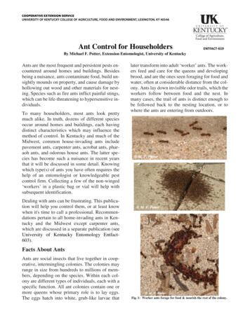
GSJ: Volume 9, Issue 3, March 2021ISSN 2320-91861437a. attracted armatureb. moving coilc. inductiond. thermale. motor operatedf. mechanicalHowever, only attracted armature types have significant2.1.1.2.STATIC RELAYFig 2.1.1.2 STATIC RELAYThe term ‘static’ implies that the relay has no moving parts. This is not strictly the case for astatic relay, as the output contacts are still generally attracted armature relays. In a protectionrelay, the term ‘static’ refers to the absence of moving parts to create the relay characteristic.Introduction of static relays began in the early 1960’s.Their design is based on the use ofanalogue electronic devices instead of coils and magnets to create the relay characteristic. Earlyversions used discrete devices such as transistors and diodes in conjunction with resistors,capacitors, inductors, etc., but advances in electronics enabled the use of linear and digitalintegrated circuits in later versions for signal processing and implementation of logic functions.While basic circuits may be common to a number of relays, the packaging was still essentially6GSJ 2021www.globalscientificjournal.com
GSJ: Volume 9, Issue 3, March 2021ISSN 2320-91861438restricted to a single protection function per case, while complex functions required several casesof hardware suitably interconnected. User programming was restricted to the basic functions ofadjustment of relay characteristic curves. They therefore can be viewed in simple terms as ananalogue electronic replacement for electromechanical relays, with some additional flexibility insettings and some saving in spacerequirements. In some cases, relay burden is reduced,making for reduced CT/VT outputrequirements.2.1.1.3.DIGI TAL RELAY SFIG2.1.1.3 DIGITAL RELAYSDigital protection relays introduced a step change in technology. Microprocessors andmicrocontrollers replaced analogue circuits used in static relays to implement relay functions.Early examples began to be introduced into service around 1980, and, with improvements inprocessing capacity, can still be regarded as current technology for many relay applications.However, such technology will be completely superseded within the next five years by numericalrelays. Compared to static relays, digital relays introduce A/D conversion of all measuredanalogue quantities and use a microprocessor to implement the protection algorithm. The7GSJ 2021www.globalscientificjournal.com
GSJ: Volume 9, Issue 3, March 2021ISSN 2320-91861439microprocessor may use some kind of counting technique, or use the Discrete Fourier Transform(DFT) to implement the algorithm. However, the typical microprocessors used have limitedprocessing capacity and memory compared to that provided in numerical relays. Thefunctionality tends therefore to be limited and restricted largely to the protection function itself.Additional functionality compared to that provided by an electromechanical or static relay isusually available, typically taking the form of a wider range of settings ,and greater accuracy. Acommunications link to a remote computer may also be provided. The limited power of themicroprocessors used in digital relays restricts the number of samples of the wave form that canbe measured per cycle. This, in turn, limits the speed of operation of the relay in certainapplications. Therefore, a digital relay for a particular protection function may have a longeroperation time than the static relay equivalent. However, the extra time is not significant in termsof overall tripping time and possible effects of power system stability.2.1.1.4.NUMERICAL RELAY SFIG 2.1.1.4.NUMERICAL RELAY SThe distinction between digital and numerical relay rests on points of fine technical detail, and israrely found in areas other than Protection. They can be viewed as natural developments ofdigital relays as a result of advances in technology. Typically, they use a specialized digital8GSJ 2021www.globalscientificjournal.com
GSJ: Volume 9, Issue 3, March 2021ISSN 2320-91861440signal processor (DSP) as the computational hardware, together with the associated softwaretools.The input analogue signals are converted into a digital representation and processed according tothe appropriate mathematical algorithm. Processing is carried out using a specializedmicroprocessor that is optimized for signal processing applications, known as a digital signalprocessor or DSP for short. Digital processing of signals in real time requires a very high-powermicroprocessor. In addition, the continuing reduction in the cost of microprocessors and relateddigital devices (memory, I/O, etc.) naturally leads to an approach where a single item ofhardware is used to provide a range of functions(‘one-box solution’ approach). By using multiplemicroprocessors to provide the necessary computational performance, a large number offunctions previously implemented in separate items of hardware can now be included within asingle item.Numerical distance relay features Distance Protection- several schemes including user definable) Overcurrent Protection (directional/non-directional) Several Setting Groups for protection values Switch-on-to-Fault Protection Power Swing Blocking Voltage Transformer Supervision Negative Sequence Current Protection Undervoltage Protection Overvoltage Protection CB Fail Protection Fault Location9GSJ 2021www.globalscientificjournal.com
GSJ: Volume 9, Issue 3, March 2021ISSN 2320-91861441 CT Supervision VT Supervision Check Synchronization Auto reclose CB Condition Monitoring CB State Monitoring User-Definable Logic Broken Conductor Detection Measurement of Power System Quantities (Current, Voltage, etc.) Fault/Event/Disturbance recorderRelay SoftwareThe software provided is commonly organized into a series of tasks, operating in real time. Anessential component is the Real Time Operating System (RTOS),whose function is to ensure thatthe other tasks are executed as and when required, on a priority basis. Other task softwareprovided will naturally vary according to the function of the specific relay, but can begeneralized as follows:a. system services software – this is akin to the BIOS of an ordinary PC, and controls the lowlevel I/O for the relay (i.e. drivers for the relay hardware, boot-up sequence, etc.)b. HMI interface software – the high level software for communicating with a user, via the frontpanel controls or through a data link to another computer running suitable software, storage ofsetting data, etc.c. application software – this is the software that defines the protection function of the relayd. auxiliary functions – software to implement other features offered in the relay – oftenstructured as a series of modules to reflect the options offered to a user by the manufacturer10GSJ 2021www.globalscientificjournal.com
GSJ: Volume 9, Issue 3, March 2021ISSN 2320-91861442Application Software. The relevant software algorithm is then applied. Firstly, the values of thequantities of interest have to be determined from the available information contained in the datasamples. This is conveniently done by the application of the Discrete Fourier Transform (DFT),and the result is magnitude and phase information for the selected quantity. This calculation isrepeated for all of the quantities of interest. The quantities can then be compared with the relaycharacteristic, and a decision made in terms of the following:a. value above setting – start timers, etc.b. timer expired – action alarm/tripc. value returned below setting – reset timers, etc.d. value below setting – do nothinge. value still above setting – increment timer, etc.f. Since the overall cycle time for the software is known,a. timers are generally implemented as counters.2.2 VARIOUS TYPES OF PROTECTION RELAY AND THEIR TRIP FUNCTIONS SPAJ140 non-directional overcurrent and earth fault protection. SPAJ110 earth fault protection. SPAM150 motor protection REF 615- Combination of SPAJ140 and SPAJ11011GSJ 2021www.globalscientificjournal.com
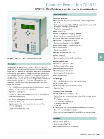
GSJ: Volume 9, Issue 3, March 2021ISSN 2320-91861443Fig 2.2 REF 615 Siemens SIPROTEC 7SJ62 line protection of high and medium voltage networks withearthed (grounded), low-resistance earthed, isolated or compensated neutral point2.3.TYPICAL 11kV HV SWITCHGEAR PROTECTION RELAY TRIP FUNCTIONSTable 2.3. Protection Relay Trip FunctionsFunctionIEC 61850IEC 60617IEC-ANSIThree-phase non-directional overcurrent protection, low PHLPTOC13I (1)51P-1 (1)PHLPTOC2stageThree-phase non-directional overcurrent protection, high PHHPTOC13I (2)3I (1)51P-1 (2)51P-2 (1)3I (2)3I (1)51P-2 (2)50P/51P (1)PHIPTOC23I (2)instantaneous stageThree-phase directional overcurrent protection, low stage DPHLPDOC1 3I (1)50P/51P (2)67-1 rrentPHHPTOC2protection, PHIPTOC1DPHLPDOC2 3I (2)12GSJ 2021www.globalscientificjournal.com67-1 (2)
GSJ: Volume 9, Issue 3, March 2021ISSN 2320-91861444Three-phase directional overcurrent protection, high stage DPHHPDOC1 3I 67-2Non-directional earth-fault protection, low stageEFLPTOC1EFLPTOC2EFHPTOC1I0 (1)I0 (2)I0 (1)51N-1 (1)51N-1 (2)51N-2 (1)EFHPTOC2Non-directional earth-fault protection, instantaneous stage EFIPTOC1I0 (2)I0 51N-2 (2)50N/51NNon-directional earth-fault protection, high stageDEFLPDEF1 I0 (1)DEFLPDEF2 I0 (2)Directional earth-fault protection, low stage67N-1 (1)67N-1 (2)Table continues on next pageDirectional earth-fault protection, high stageDEFHPDEF1 I0 Transient / intermittent earth-fault protectionINTRPTEF1 I0 IEFNon-directional (cross-country) earth fault protection, EFHPTOC1 I0 67N-267NIEF51N-2Negative-sequence overcurrent protectionNSPTOC1NSPTOC2Phase discontinuity protectionPDNSPTOC1Residual overvoltage protectionROVPTOV1ROVPTOV2ROVPTOV3Three-phase undervoltage protectionPHPTUV1PHPTUV2PHPTUV3Three-phase overvoltage protectionPHPTOV1PHPTOV2PHPTOV3Positive-sequence undervoltage protectionPSPTUV1Negative-sequence overvoltage protectionNSPTOV1Three-phase thermal protection for feeders, cables and T1PTTR1I2 (1)I2 (2)I2/I1 U0 (1)U0 (2)U0 (3)3U (1)3U (2)3U (3)3U (1)3U (2)3U (3)U1 U2 3Ith F46 (1)46 (2)46PD59G (1)59G (2)59G (3)27 (1)27 (2)27 (3)59 (1)59 (2)59 (3)47U 47O49FThree-phase thermal overload protection for power T2PTTR13Ith T49TNegative-sequence overcurrent protection for motorsMNSPTOC1 I2 M (1)46M (1)Loss of load supervisionMotor load jam protectionMotor start-up supervisionPhase reversal protectionThermal overload protection for motorsBinary signal PTTR1BSTGGIO146M (2)3751LR49,66,48,51LR46R49MBST13GSJ 2021www.globalscientificjournal.comI2 M (2)3I Ist Is2t n I2 3Ith MBST
GSJ: Volume 9, Issue 3, March 2021ISSN 2320-91861445Stabilized and instantaneous differential protection for TR2PTDF13dI T87T3dI L87LLine differential protection and related measurements,stabilized and instantaneous stagesLNPLDF1Numerical stabilized low impedance restricted earth-fault LREFPNDF1 dI0Lo 87NLHigh impedance based restricted earth-fault protectionHREFPDIF1dI0Hi 87NHCircuit breaker failure protectionThree-phase inrush detectorCCBRBRF1INRPHAR13I /I0 BF3I2f 51BF/51NBF68CHAPTER 3MATERIALS AND METHODS3.1 RESEARCH MATERIALSData required for the purpose of analysis and investigation of the study area was collected fromNigeria Liquefied Natural Gas (NLNG) Substation 37 and Substation 29 11kV installation. Themethod and procedure adopted in this research are described accordingly.3.1.1. The Purpose of this test is to define and describe the method, tests and test sequence ofconnections required to investigate the root cause of the tripping at the HV switchgear SB37D1SIEMEN multifunction protection relay (7SJ8031-5EB00-3FB0).In order to investigate the cause of the tripping two (2) separate analyses shall be carried out:1. To determine, if the Emergency Diesel Generator G-0001 is a factor in the tripping ofthe SB29C1-3, Siemens multifunction protection relay (7SJ8031-5EB00-3FB0), therelated static load test will be executed again, but in different sequences2. 2nd investigation will analyze the whole electrical system of the Bonny River airstrippowered through the HV switchgear SB29C114GSJ 2021www.globalscientificjournal.com
GSJ: Volume 9, Issue 3, March 2021ISSN 2320-91861446To support both investigations, three phase power quality analyzer (C.A 8332B) shall beinstalled to verify the current conditions, positioned as follow;a.Three phase power quality analyzer (C.A 8332B) connected to the EDG G-0001 toverify the output parameters from the EDG (positioned at the bus bar on EDG powerpart.b.Three phase power quality analyzer (C.A 8332B) connected to the airstrip electricalsystem to verify the general output parameters (positioned at the LV switchgearSB29N1/2.H)Note:i.Circuits to be de-isolated:a)Rack in SB29N1/1.H.- Incoming Emergency Diesel Generator G-0001 feeder on LVswitchgear SB29N1b)ii.SB29N1/4.M – Spare Breaker on LV Switchgear SB29N1.Circuits to be Isolateda)SB29N1/3.H – SB29N12 MDB Terminal Building Ground Floorb)SB29N1/3.M – SB29N13 SDB Terminal HVAC GFc)SB29N1/5.M – SB29N15 SDB Gate house 2d)SB29N1/5.L – SB29N14 SDB Fire Rescuee)Partial isolation of SB29N11 SDB SubstationThis distribution board SB29N11 shall be partially isolated- lighting circuits (SB29N11/02) andsmall power outlets (SB29N11/09, 10, & 11) shall be energised for test purpose within theelectrical roomf)SB29N1/5.N-5.P- UP29V2 30kVA AC UPS Systemg)SB29N1/4.D-4.H – UP29V1 160kVA AC UPS System3. Energization of above mentioned circuit after test,- By NLNG Authorised Personnel15GSJ 2021www.globalscientificjournal.com
GSJ: Volume 9, Issue 3, March 2021ISSN 2320-918614474. Return all electrical installation to Normal running mode (pre-test status) after tests By NLNG Authorized personnel.3.1.2. TEST METHOD STATEMENTPreliminaries-All necessary permits (isolation permit/clearance certificate) shall be obtained beforethe test starts-Appropriate equipments / tools shall be used-Pre check of materials / equipments to be used for the test shall be carried out-Advance notice to the consumers connected to SB29N1 (BRTA)3.1.3. Three Phase Power Quality Analyzer: C.A 8332BThe measurements and connections shall be made strictly according to manufacturer user manualand instructions.The principal measurements made are:-Measurement of AC rms voltages up to 480V (phase –to-phase) and of AC rms currentfor four wire networks.-Measurement of the frequency of 50Hz networkCalculation of the power,-Calculation of active, reactive and apparent power per phase and their aggregate.-Calculation of neutral current by vector summing of phase current for star configurations.-Calculation of the peak factors for current and voltages-Calculation of the phase unbalance for voltages and current (three-phase network only).16GSJ 2021www.globalscientificjournal.com
GSJ: Volume 9, Issue 3, March 2021ISSN 2320-918614483.2.0. TESTS TO BE CARRIED OUTTo determine/verify, if the Emergency Diesel Generator (EDG) (G-0001) is a factor in thetripping of the SB29C1-3, Siemens multifunction protection relay (7SJ8031-5EB00-3FB0) thefollowing tests shall be executed:1.Emergency Diesel Generator G-0001 synchronization to grid/ static load test withtransformer only (gradually increase the load from 10% to 100%).2.Checking the entire BRTA electrical system without the EDG G-0001 by:a) Connecting the three phase power quality analyzer: C.A 8332B to the LVswitchgear terminal SB29N1/2.H, and taking the parameters on the analyzer at 1sinterval for 20 minutes, with the Terminal building HVAC panel SB29N13 (SB29N1/3.M)energized while other circuits remain in off positionb) Connecting the three phase power quality analyzer: C.A 8332B to the LVswitchgear terminal SB29N1/2.H, and taking the parameters on the analyzer at 1sinterval for 20 minutes, with the substation panel SB29N11 HVAC circuits(18, 19, 20, 21, 22, 23 & 24) energized while other circuits remain in off position.c)Connecting the three phase power quality analyzer: C.A 8332B to the LVswitchgear terminal SB29N1/2.H, and taking the parameters on the analyzer at 1sinterval for 20 minutes, with all other circuits:SB29N1/5.M – SB29N15 SDB Gate house 2SB29N1/5.L – SB29N14 SDB Fire RescueSB29N1/5.K - SB29N11 SDB SubstationThis distribution board SB29N11 shall be partially isolated- HVAC circuits (SB29N11/18, 19,20, 21, 22, 23 & 24) shall be in off position – Reference Attachment 6.3SB29N1/5.N-5.P- UP29V2 30kVA AC UPS System17GSJ 2021www.globalscientificjournal.com
GSJ: Volume 9, Issue 3, March 2021ISSN 2320-91861449SB29N1/4.D-4.H – UP29V1 160kVA AC UPS System energized.The terminal building HVAC panel SB29N13 shall remain in off position3.2.1. TEST SEQUENCEBefore any test shall be carried out, three phase power quality analyser (C.A 8332B) will beinstalled:Phase 1: Connection of three phase power quality analyser C.A 8332Bi.Three phase power quality analyser (C.A 8332B) installed on the EDG output on the LVSwitchgear (SB29N1/1.H)ii.Three phase power quality analyzer (C.A 8332B) installed on the transformer output onthe LV switchgear (SB29N1/2.H)Phase 2: Emergency Diesel Generator Static load test to Grid with transformer TR29CN1onlyIn order to investigate the tripping of the HV Switchgear SB29C1-3 Siemens multifunctionprotection relay (7SJ8031-5EB00-3FB0), the tests on the Emergency Diesel Generator shall becarried out (as mentioned in section 4 - Test to be carried out):Emergency Diesel Generator G-0001 synchronization to grid/ static load test with transformeronly (gradually increase the load from 10% to 100%).Phase 3: BRTA electrical system check without the EDG G-0001.Checking the entire BRTA electrical system without the EDG G-0001.Phase 1: Connection of three phase power quality analyzer C.A 8332B-Generator Panel18GSJ 2021www.globalscientificjournal.com
GSJ: Volume 9, Issue 3, March 2021ISSN 2320-91861450Fig3.2.1a: Typical Three Phase Power Quality Analyzer ConnectionNL1L2L3Three phase poweranalyzer C.A 8332BFig3.2.1b: Typical Three Phase Power Quality Analyzer ConnectionCURRENT LEADS(AmpFlex) TYPICALCONNECTION3.2.2. Step 1.Connection of Thethree (3) phase power quality analyzer (C.A 8332B) to bus bar on emergencydiesel generator G-0001 power part terminal19GSJ 2021www.globalscientificjournal.com
GSJ: Volume 9, Issue 3, March 2021ISSN 2320-91861451The three (3) phase power quality analyzer (C.A 8332B) current measurement probe (Ampflex)is clamped round the bus bar on EDG power part terminal. Green Ampflex cable clamped around L1 bus bar on EDG power part terminal Yellow Ampflex cable clamped around L2 bus bar on EDG power part terminal Red Ampflex cable clamped around L3 bus bar on EDG power part terminalThe neutral current shall be calculated by the three phase power quality analyzer (C.A 8332B).3.2.3. Step 2:The three (3) phase power quality analyzer (C.A 8332B) voltage measuring leads are clamped tothe bus bar on the EDG Q201 control panel terminal Clamp green voltage lead to L1 bus bar on EDG power part terminal Clamp yellow voltage lead to L2 bus bar on EDG power part terminal Clamp red voltage lead to L3 bus bar on EDG power part terminal Clamp blue voltage lead to N bus bar on EDG power part terminal20GSJ 2021www.globalscientificjournal.com
GSJ: Volume 9, Issue 3, March 2021ISSN 2320-91861452CHAPTER 4RESULTS AND DISCUSSION4.1 RESULT ANALYSISTable.4.1: Relay protection FunctionsOmicron was used to check the time before the vacuum contactor opens.It is capable of analyzing the system.21GSJ 2021www.globalscientificjournal.com
GSJ: Volume 9, Issue 3, March 2021ISSN 2320-918614534.2 Analysis from Sequence of Operation Result.The result obtained from the tripping test carried out showed that the tripping time from theOmicron for test 1 on L1 is 91.2 Sec while the actual tripping of the Vacuum Contactor trippedat 82.4 Sec:Table 4.2: Transformer Neutral Earth FaultFig.4.2a Sequence of Operation Event Summary Report on Ojoto 11kv Feeder (New Case)Fig.4.2d Sequence of Operation Event Summary Report on Wokoma 11kv Feeder (NewCase)4.3. NON-DIRECTIONAL EARTH FAULTTable 4.3. Relay Protection Functions4.4Result Summary and Discussion4.4.1Sequence of OperationThe results obtained from the existing relay coordination (with CTR 1200/5 for T1A and T2Aand time step delay of 0.3sec to 1.2sec) and new case relay coordination (with CTR 800/5 forFIG 4.3- SLD- 11kV HV SWITCHGEAR22GSJ 2021www.globalscientificjournal.com
GSJ: Volume 9, Issue 3, March 2021ISSN 2320-91861454FIG 4.4. SS37 SB37BD1 RELAY PROTECTION SETTING AN
Nuisance tripping of the HV Switchgear Protection relay. In other words, to reduce and eliminate unnecessary faults on the power system configuration. A power system is capable of meeting the present load and has the flexibility to meet the future