Transcription
CENTRUFUGAL SWITCHREPLACEMENT/ADJUSTMENT(Motor Fan-End Locations)INSTRUCTIONSFor questions or help with this product contact Tech Support at (570) 546-9663 or techsupport@grizzly.comApplicationThese instructions cover typical removal,replacement, and adjustment of centrifugal switchassemblies located on the fan end of most Grizzlysingle-phase or split-phase induction motorsunder five horsepower. For switches located atthe pulley end of the motor, these instructions donot apply.The typical centrifugal switch assembly consistsof two main parts. A contact plate equipped with points that ismounted to the fixed motor housing.A fly-weight and spring assembly called theactuator is mounted to the motor shaft.For your own safety and protection ofproperty, consult a qualified electrician ifyou are unsure about wiring practices orelectrical codes in your area.Before You Begin Read all safety instructions, take the requiredprecautions, and make sure that you arequalified to do the work. If not, consult aqualified electrician. Disconnect the machine from power! Make sure the start capacitor is functionaland is not the reason why the motor is slowto start, or not starting at all. Make sure that the power supply circuit hasthe correct voltage and the machine plug iscorrectly wired. Make sure that all wires including groundshave continuity, and their connections aretight. Make sure the motor windings are not shortedor open. Make sure the motor bearings are ingood condition, and the motor shaft end-playis minimal.FunctionWhen the motor is OFF and at rest, the pointson the contact plate are closed. When the motoris started, current is sent to the start capacitor,through the closed contact plate points, and thento the motor start windings to get the motor up tofull speed as fast as possible.When the speed of the motor shaft gets close tothe rated motor speed, centrifugal force causesthe flyweights to override actuator spring tension,swing out, and open the contact points. When thepoints are open, current is cut to the start windingsand the start capacitor, allowing them to cool. Atthis point, the run windings take over and operatethe motor. (Note: Often a run capacitor is used inthe run circuit to increase motor efficiency.)When the motor is turned OFF, centrifugal forcediminishes, and the springs draw the flyweightsback in (sometimes with a click sound), returningthe contact points to the closed position.Items NeededPhillips Screwdriver #2. 1Standard Screwdriver #2. 1Combination Wrench Set. 1Sandpaper 100-120 Grit. As NeededLight-Duty Thread Locking Fluid. 1-DropCopyright MAY, 2011 By Grizzly Industrial, Inc.Warning: No portion of this manual may be reproduced in any shapeOr form without the written approval of Grizzly Industrial, inc.#CR14099 printed in USA
SHOCK HAZARD. It is extremely dangerous toperform any wiring or electrical procedure whileequipment is connected to the power supply.Touching electrified parts will result in severeburns, electrocution, or death. Always disconnectall equipment from the power supply beforeservicing electrical components!QUALIFIED ELECTRICIAN. To reduce the riskof burns, electrocution, fire, or equipment damage,only an electrician or qualified service personnelshould perform wiring tasks or electrical serviceprocedures.MODIFICATIONS. Unapproved modificationsmay lead to unpredictable results, includingserious injury, electrocution, or fire. This includesinstallation of unapproved aftermarket parts.CIRCUIT REQUIREMENTS. Unless otherwiseapproved an a qualified electrician, circuitrequirements at the beginning of your Grizzlymachine Owner's Manual MUST be followedwhen connecting the machine or equipment to apower supply.-2-WIRE CONNECTIONS. All connections must betight enough to prevent wires becoming loosewhen exposed to vibration. Double-check all wiresdisconnected or connected during any wiringprocedure to ensure tight connections.WIRE/COMPONENT DAMAGE. Damagedwires or components increase the risk of burns,electrocution, fire, or machine damage. Alwaysimmediately replace damaged components beforeresuming operations.CAPACITORS/INVERTERS. Some capacitorsand power inverters store an electrical charge forup to 10 minutes after being disconnected fromthe power source. To reduce the risk of beingshocked, wait at least this long before working oncapacitors.EXPERIENCING DIFFICULTIES. If you areexperiencing difficulties understanding theinformation included in this section, contact ourTechnical Support at (570) 546-9663.Centrifugal Switch Replacement and Adjustment
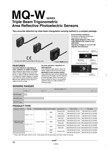
Centrifugal Switch Replacement and Adjustment1. DISCONNECTTHE MACHINEAND MOTORFROM POWER!2. Remove thefan coverscrews.3. Removethe fan cover togain access tothe fan hub.Steel Fan & Hub4. Loosen thefan hub fastenerand slide the fanoff.Centrifugal Switch Replacement and AdjustmentPlastic Fan & HubTip: Never pry orhammer on a fanor motor shaft.Doing so will benda steel fan, crackplastic ones, ormushroom the endof a motor shaft,requiring motor orfan replacement.Tip: For removalof this fan model,use a screwdriverto expand thehub slightly.-3-
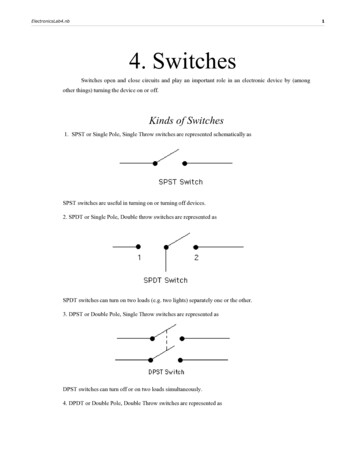
5. If equipped,remove thedust coverscrews, and thedust cover.DustCover6.To adjust,loosen the collarscrew, slide theactuator againstthe contact plateuntil the pointsjust close. Thenretighten thescrew to hold theadjustment.To replace, go toStep 7.Points OpenCollar ScrewPoints ClosedTip: Clean carbonfrom the pointswith a piece offolded sandpaper.Actuator7. If only replacingthe contact plate,mark the centrifugal switchlocation on theshaft.Note: The switchcontact points arepositioned at oneo'clock on bothstyles of motors.8.Note: Typicallyonly two mountingscrews are usedto fasten theswitch.-4-Mark all wirepositions, andloosen the collar screw andremove the centrifugal switch.Centrifugal Switch Replacement and Adjustment
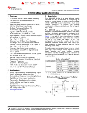
10. Carefullyinspect all wireswhere theyenter the motorfor chaffing,overheating, andloose terminals(repair asrequired).Capacitor WireStartWindingWireNote: Wires canwear on castingedges. Overloadedwires may havewrinkled ormelted insulation.Overloaded motorwindings oftenhave a strongsmell and showbubbled varnish.11. Vacuum out the motor so all built-up dust and contaminants are removed.12. Install the new switch and wires at the same locations.13. Install the actuator and adjust the switch as described in Step 6.14. Reassemble all components in reverse order of removal. Make sure that all wires are routed awayfrom moving parts and sharp edges, and that you use thread locking fluid on the fan retainingscrew.15. Test run the motor.Centrifugal Switch Replacement and Adjustment-5-
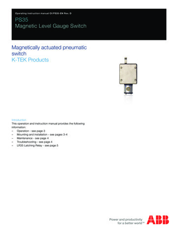
***Tech Support Bulletin***Adjusting Internal Motor PointsMachine Clarification, FAQ’s, Diagrams, Charts, Notices, and Other Recent UpdatesStep 1Remove the end-bell bolts on both sides of the motor. Tap the drive shaft (pulley side) with a rubber mallet,and remove the shaft and opposite end-bell. Once those two parts are removed, the remaining end-bellcontaining the contact points can be pried off.Step 2Below is how the motor should look after tapping the shaft out and prying the remaining end-bell off.EndFrameRotorContactPlateCopyright October, 2013 By Grizzly Industrial, Inc.Warning: No portion of this manual may be reproduced in any shapeor form without the written approval of Grizzly Industrial, inc.
Step 3The centrifugal switch shown below is not adjustable on motors with internal contact points. The centrifugalswitch is permanently pressed on the shaft and cannot be moved without damaging it. The only way toadjust separation of the contact points is to shim the entire contact plate itself.Step 4Shown below are the actual contact points. These points are held closed by the centrifugal switch shownin the photo above. When these points are closed, the start winding and start capacitor are in circuit for theinitial start of the motor. Once the motor reaches a certain speed, the centrifugal switch will open and allowthese points to separate and stop the flow of electricity to the start capacitor and start windings. If thesecontact points are open when the motor is being started, it will usually just buzz or hum.-2-Adjusting Internal Motor Points Tech Bulletin
Step 5Since the centrifugal switch is not adjustable in this type of motor, as shown in the previous photo, the contact plate will need to be moved outward by shimming underneath it with flat washers. To do this, start byremoving the two Phillips head screws shown below. Remove the contact plate, and place one flat washerover each hole where the Phillips screws are threaded into.PhillipsScrewPhillipsScrewStep 6Re-attach the contact plate to the motor end-bell, making sure that the screw is going through both thecontact plate and the washer that is placed underneath it. Then, re-assemble the motor and test it to makesure that it starts properly. The fan and fan cover do not need to be installed for testing.Adjusting Internal Motor Points Tech Bulletin-3-
Centrifugal switch replacement and Adjustment -5-11. Vacuum out the motor so all built-up dust and contaminants are removed. 12. install the new switch and wires at the same locations. 13. install the actuator and adjust the switch as described in Step 6. 14. reassemble all components in reverse o