Transcription
Inspection, Testing and Commissioning of Electrical Switchboards,Circuit Breakers, Protective Relays, Cables and PLCs
THIS BOOK WAS DEVELOPED BY IDC TECHNOLOGIESWHO ARE WE?IDC Technologies is internationally acknowledged as the premier provider of practical, technical trainingfor engineers and technicians.We specialize in the fields of electrical systems, industrial data communications, telecommunications,automation and control, mechanical engineering, chemical and civil engineering, and are continuallyadding to our portfolio of over 60 different workshops. Our instructors are highly respected in their fieldsof expertise and in the last ten years have trained over 200,000 engineers, scientists and technicians.With offices conveniently located worldwide, IDC Technologies has an enthusiastic team of professionalengineers, technicians and support staff who are committed to providing the highest level of training andconsultancy.TECHNICAL WORKSHOPSTRAINING THAT WORKSWe deliver engineering and technology training that will maximize your business goals. In today’scompetitive environment, you require training that will help you and your organization to achieve its goalsand produce a large return on investment. With our ‘training that works’ objective you and yourorganization will: Get job-related skills that you need to achieve your business goals Improve the operation and design of your equipment and plant Improve your troubleshooting abilities Sharpen your competitive edge Boost morale and retain valuable staff Save time and moneyEXPERT INSTRUCTORSWe search the world for good quality instructors who have three outstanding attributes:1. Expert knowledge and experience – of the course topic2. Superb training abilities – to ensure the know-how is transferred effectively and quickly to you ina practical, hands-on way3. Listening skills – they listen carefully to the needs of the participants and want to ensure that youbenefit from the experience.Each and every instructor is evaluated by the delegates and we assess the presentation after every class toensure that the instructor stays on track in presenting outstanding courses.HANDS-ON APPROACH TO TRAININGAll IDC Technologies workshops include practical, hands-on sessions where the delegates are given theopportunity to apply in practice the theory they have learnt.REFERENCE MATERIALSA fully illustrated workshop book with hundreds of pages of tables, charts, figures and handy hints, plusconsiderable reference material is provided FREE of charge to each delegate.ACCREDITATION AND CONTINUING EDUCATIONSatisfactory completion of all IDC workshops satisfies the requirements of the International Associationfor Continuing Education and Training for the award of 1.4 Continuing Education Units.IDC workshops also satisfy criteria for Continuing Professional Development according to therequirements of the Institution of Electrical Engineers and Institution of Measurement and Control in theUK, Institution of Engineers in Australia, Institution of Engineers New Zealand, and others.
CERTIFICATE OF ATTENDANCEEach delegate receives a Certificate of Attendance documenting their experience.100% MONEY BACK GUARANTEEIDC Technologies’ engineers have put considerable time and experience into ensuring that you gainmaximum value from each workshop. If by lunchtime on the first day you decide that the workshop is notappropriate for your requirements, please let us know so that we can arrange a 100% refund of your fee.ONSITE WORKSHOPSAll IDC Technologies Training Workshops are available on an on-site basis, presented at the venue ofyour choice, saving delegates travel time and expenses, thus providing your company with even greatersavings.OFFICE LOCATIONSAUSTRALIA INDIA IRELAND MALAYSIA NEW ZEALAND SINGAPORE SOUTH AFRICA UNITED KINGDOM UNITED STATESidc@idc-online.comwww.idc-online.comVisit our website for FREE Pocket GuidesIDC Technologies produce a set of 6 Pocket Guides used bythousands of engineers and technicians worldwide.Vol. 1 – ELECTRONICSVol. 4 – INSTRUMENTATIONVol. 2 – ELECTRICALVol. 5 – FORMULAE & CONVERSIONSVol. 3 – COMMUNICATIONS Vol. 6 – INDUSTRIAL AUTOMATIONTo download a FREE copy of these internationally best selling pocket guides go to:www.idc-online.com/downloads/On-Site TrainingSAVE MORETHAN 50% OFFthe per personcostCUSTOMISE thetraining to YOURWORKPLACE!Have the trainingdelivered WHENAND WHERE youneed it!All IDC Technologies Training Workshops are available on an on-site basis, presented at the venue ofyour choice, saving delegates travel time and expenses, thus providing your company with evengreater savings.For more information or a FREE detailed proposal contact Kevin Baker by e-mailing:training@idc-online.com
IDC TECHNOLOGIESWorldwide OfficesAUSTRALIATelephone: 1300 138 522 Facsimile: 1300 138 533West Coast Office1031 Wellington Street, West Perth, WA 6005PO Box 1093, West Perth, WA 6872INDIATelephone : 91 44 3061 8525131 G.N. Chetty Road, Chennai 600017IRELANDTelephone : 353 1 473 3190 Facsimile: 353 1 473 3191Caoran, Baile na hAbhann, Co. GalwayMALAYSIATelephone: 60 3 5192 3800 Facsimile: 60 3 5192 380126 Jalan Kota Raja E27/E, Hicom Town CenterSeksyen 27, 40400 Shah Alam, SelangorNEW ZEALANDTelephone: 64 9 263 4759 Facsimile: 64 9 262 2304Parkview Towers, 28 Davies Avenue, Manukau CityPO Box 76-142, Manukau CitySINGAPORETelephone: 65 6224 6298 Facsimile: 65 6224 7922100 Eu Tong Sen Street, #04-11 Pearl’s Centre, Singapore 059812SOUTH AFRICATelephone: 27 87 751 4294 or 27 79 629 5706 Facsimile: 27 86 692 436868 Pretorius Street, President Park, MidrandPO Box 389, Halfway House 1685UNITED KINGDOMTelephone: 44 20 8335 4014 Facsimile: 44 20 8335 4120Suite 18, Fitzroy House, Lynwood Drive, Worcester Park, Surrey KT4 7ATUNITED STATESToll Free Telephone: 1800 324 4244 Toll Free Facsimile: 1800 434 404510685-B Hazelhurst Dr. # 6175, Houston, TX 77043, USAWebsite: www.idc-online.comEmail: idc@idc-online.com
PresentsInspection, Testing and Commissioningof Electrical Switchboards,Circuit Breakers, Protective Relays,Cables and PLCsRevision 1Website: www.idc-online.comE-mail: idc@idc-online.com
IDC Technologies Pty LtdPO Box 1093, West Perth, Western Australia 6872Offices in Australia, New Zealand, Singapore, United Kingdom, Ireland, Malaysia, Poland, United States ofAmerica, Canada, South Africa and IndiaCopyright IDC Technologies 2011 All rights reserved.First published 2011ISBN: 978-1-921716-86-7All rights to this publication, associated software and workshop are reserved. No part of this publicationmay be reproduced, stored in a retrieval system or transmitted in any form or by any means electronic,mechanical, photocopying, recording or otherwise without the prior written permission of the publisher. Allenquiries should be made to the publisher at the address above.DisclaimerWhilst all reasonable care has been taken to ensure that the descriptions, opinions, programs, listings,software and diagrams are accurate and workable, IDC Technologies do not accept any legal responsibilityor liability to any person, organization or other entity for any direct loss, consequential loss or damage,however caused, that may be suffered as a result of the use of this publication or the associated workshopand software.In case of any uncertainty, we recommend that you contact IDC Technologies for clarification or assistance.TrademarksAll logos and trademarks belong to, and are copyrighted to, their companies respectively.AcknowledgementsIDC Technologies expresses its sincere thanks to all those engineers and technicians on our trainingworkshops who freely made available their expertise in preparing this manual.
Contents1Fundamentals of ns of Switchgear2.12.22.32.42.5345Single Line DiagramTypical Construction – LV/MV and HVActive and Passive Network ComponentsCircuit Breaker UtilisationFuse SwitchesHV Fuses in Combination with and as an Alternative toCircuit BreakersAuto-reclosers and Auto-reclose operations679Switchgear ratings – Highest System and Impulse WithstandVoltages, Load and Short Circuit Currents9Simple and Complex Protection Schemes14Switchgear Ancillaries, Measurement CTs, VTs and Relays 14Cable Terminations17Indoor and Outdoor Operation of Switchgear19Short Circuit Testing213.13.23.33.421222526Symmetrical and Asymmetrical RatingsMake and Break OperationsUnderstanding Test OscillogramsCase Study – Specification for a 132kV SwitchboardSwitchgear Diagnostics, Testing and 45475965697173Asset RecordsCondition Based Maintenance (CBM)Reliability Centered Maintenance (RCM)Switchgear Inspection MethodologiesDiagnostic TechniquesPrinciples of Circuit Breaker MaintenanceOil TestingMaintenance of Vacuum Circuit Breakers and SF6Switchgear Defects and Defect ControlSwitchgear InstallationsPower System Protection Principles and Relays795.15.25.35.45.55.6798184858695Principles of Protection and Need for Protective ApparatusTypes of FaultsTypes of Protection SystemsTypes of Protective RelaysElectromechanical and Static RelaysNumerical Relays
67Configuration of Numerical g Commissioning and Periodic Testing7.67.77.87.98IntroductionSetting Approach in Conventional RelaysConfiguring Numerical RelaysConfiguration Security Through PasswordsProtection Settings as Part of a ConfigurationMethods Adopted for Setting Numerical RelaysExamples of Front Panel Configuration SequenceConfiguration Exercises for Typical Relays/SimulationSoftwareReview of Codes for TestingDrum Length ChecksPost Installation CheckingPre-commissioning and Periodic TestsTests as Tools for Condition Monitoring and Early FailureAlarmHV Tests Using DC and Very Low Frequency ACPartial Discharge Tests and Mapping of ResultsDielectric Dissipation Factor MeasurementsMicro Destructive and Non-Destructive Tests for LifeAssessmentOperation and Maintenance of Cables129130133137140140Cable Failure Modes and Fault pes of FailuresReasons for FailuresFault LocationElectrical Tests for Detection of Cable FaultsSafety Issues in Fault DetectionAnalysis of FailuresSwitchboard installation, inspection and 63Receiving, Handling and StorageInspectionInstallationType, Routine, Acceptance and Pre-comissioning TestsHigh Voltage Equipment Test TechniquesCommissioning ProceduresInterface to Control Equipment ew of PLCPLC I/O ModulesPre-Commissioning TestsCommissioning ProceduresTypical Faults
11Case Studies of Typical 8178179180Improper Circuit Breaker Trip Unit and Relay SettingsMotor Overload ProtectionMedium Voltage Distribution System Installation ProblemsSwitchboard Metering ProblemsEmergency Distribution ProblemsNoisy TransformersIncorrect Earthing and Neutrals
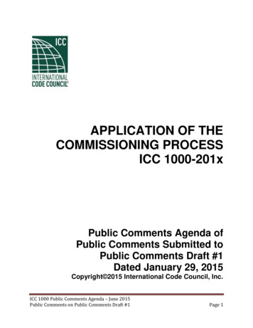
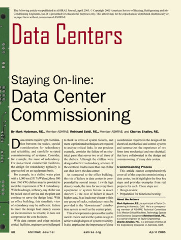
1Fundamentals of SwitchgearIn this chapter, we will learn about one of the basic, but most important components of any electricalsystem, namely the Switchgear. As a preparatory step towards the understanding of switchgears, wewill review the use of electrical single line diagrams and the types of components that make upelectrical systems. We will also study the various applications of switchgear in the later part of thischapter.Learning objectives 1.1Single line diagramsTypical construction – LV/MV and HVActive and passive network componentsCircuit breaker utilizationFuse switchesHV fuses in combination with and as alternatives to circuit breakersAuto-reclosers and auto-reclose operationsSingle line diagramElectrical systems are mostly made up in the form of three phase configuration. However trying torepresent three phase systems in drawings as actual three phase connections may not only be laboriousbut also make the drawing quite difficult to understand. This is where the concept of single linediagram comes into being. The term 'Single line diagram' simply means that the three phase nature ofthe circuits and components is ignored. Figure 1.1 shows a typical example of a high voltagedistribution network, represented as a single line diagram, complete with transformer infeeds, cableand overhead circuits, distribution substations, circuit breakers and other network switchgear.
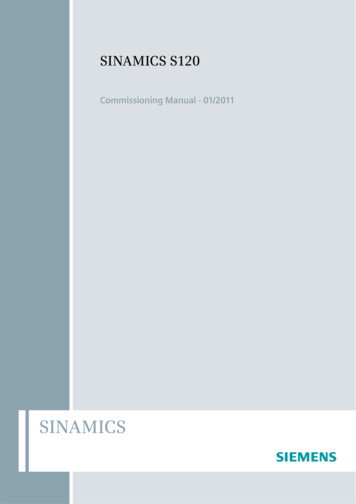
2Inspection, Testing and Commissioning of Electrical Switchboards, Circuit Breakers, Protective Relays, Cables and PLCsFigure 1.1Typical network as a single line diagram1.2Typical construction – LV/MV and HVCircuit breakers come in a variety of types. The prominent types being: Bulk oil circuit breaker Minimum oil circuit breaker Air blast circuit breaker Vacuum circuit breaker SF6 circuit breakerFigure 1.2 shows the construction of a typical bulk oil type circuit breaker. Such breakers used oil asthe insulation medium and were very heavy and bulky. They also posed serious fire hazards and oil
Fundamentals of Switchgear3pollution problems. With the advancements in technology such breakers have over a period of timebeen gradually replaced with more compact and versatile vacuum and SF6 breakers.Figure 1.2Bull oil circuit breakerFigure 1.3 shows the typical construction of a minimum oil circuit breaker. Similar to bulk oil breaker,oil is used as the insulation medium in this breaker. However, as the name implies, much lesserquantity of oil is used in this type of breaker. Porcelain is used for the construction of the body andminimum oil circuit breakers have much smaller foot prints than the bulk oil breakers.Figure 1.3Small oil volume circuit breaker (one phase shown)Figure 1.4 shows the typical construction of an air blast circuit breaker. High pressure air is used asinsulation and arc extinguishing medium. Disadvantages of this type of breaker are the need for acompressed air plant and associated pipe lines.
4Inspection, Testing and Commissioning of Electrical Switchboards, Circuit Breakers, Protective Relays, Cables and PLCsFigure 1.4Basic air blast circuit breakerFigure 1.5 shows the construction details of a vacuum interrupter. Vacuum is used for interrupting andextinguishing the arc at the time of the breaker operation. The ceramic cartridge contains the fixed andmoving electrodes maintained under high vacuum conditions. Owing to the sealed nature of theinterrupter, the vacuum breaker is impervious to external dust and pollution conditions.Figure 1.5Vacuum interrupterFigure 1.6 depicts the construction details of a typical SF6 gas insulated breaker with a vacuuminterrupter. SF6 gas under pressure is used as the insulation medium and this enables the breaker to beconstructed quite small and compact. The pressure of the gas needs monitoring on a continuous basisand the purity of the gas has to be checked periodically to maintain the effectiveness of the breaker.
Fundamentals of Switchgear5Figure 1.6Vacuum interrupter in SF6 enclosure switchgear, with rated three position disconnector (isolator)1.3Active and passive network componentsNetwork components may be divided into two broad categories, those that are continuously in usewhenever electricity is being supplied, called the ACTIVE components and those called upon tofunction only when required to do so, the PASSIVE components.ACTIVE components comprise transformers, cables, overhead lines and metering equipment and maybe considered the main revenue earning elements. PASSIVE components compose mainly switchgearin its various forms, together with switchgear's ancillaries, current and voltage transformers andprotection relays. These components perform no revenue earning function and may be considered as anadded cost, and to be minimized wherever possible.1.4Circuit breaker utilisationIn an ideal network having perfect reliability and no maintenance or repair requirement, there is noneed to break the electric circuits; however, this is impossible; therefore switchgear has to be installed.However, we should be careful not to install more switchgear than is absolutely required and theswitchgear that is installed should have no more functionality than is necessary.The two most common forms of medium voltage switchgear are automatic circuit breakers and nonautomatic, load breaking, fault making switches. The main function of a circuit breaker is toautomatically interrupt fault current, although an important secondary function is to close onto a faultand thereby make fault current. This function may be required during for example, fault location. Theautomatic disconnection of faults by circuit breakers allows the remainder of the network to continue inoperation, after the faulty branch has been disconnected. Without this feature, network operation wouldbe 'all or nothing'.In theory all the switchgear shown in Figure 1.1 could be implemented by circuit breakers, but thischoice would be very expensive and result in an excessive maintenance burden. In practice, circuit
6Inspection, Testing and Commissioning of Electrical Switchboards, Circuit Breakers, Protective Relays, Cables and PLCsbreakers are normally located only at the beginning of the cable, overhead line or mixed circuit, wherethey serve to disconnect faults either phase to phase or phase to neutral/earth (or both).1.5Fuse switchesHistorically, circuit breakers were also utilized at each distribution substation, to control and protectthe transformer, although fuse switches may nowadays implement this function. Figure 1.7 shows thecross section of a typical switchfuse unit.Figure 1.7Fuse switch in cross section1.6HV fuses in combination with and as alternative to circuitbreakersMedium voltage fuses are available up to a current rating equivalent to a three phase rating ofapproximately 1.5 MVA and offer a cost-effective means of transformer protection. Generally they arecombined with a three phase disconnector and a 'trip all phases' device, so that if one fuse fails, thedisconnector trips and the supply to the transformer are fully disconnected. If this device were notfitted, the transformer may be subjected to 'single phasing' and a corresponding low LV side voltage.The use of fuses over circuit breaker has the advantage of lower cost of installation and very fastdisconnection (typically less than half a cycle) in the event of a fault. However the disadvantage is theamount of time needed to replace the blown fuse and inability to close or open the circuit from aremote location.
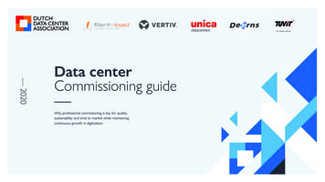
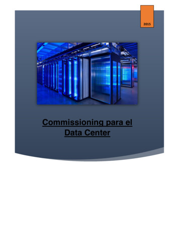
Fundamentals of Switchgear7Where fuses are used in conjunction with reclosing type circuit breakers, the satisfactory operation of acircuit breaker in association with fuses depends upon the degree of co-ordination obtained, requiringthat the time/current characteristic of the re-closed circuit breaker be graded with those of the fuses togive optimum discrimination. The first trips must be short enough that the fuses are not degraded,whilst the second and third must be long enough to allow the fuses to operate.1.7Auto-reclosers and auto-reclose operationsIn networks comprising substantial lengths of overhead line, many of the faults that occur are transientin nature. These are caused for example by wind blown debris bridging conductors, insulator flashover,etc. The reliability of the supply may be considerably improved by arranging for the controlling circuitbreaker to re-close automatically after a fault occurs. This ensures that for transient faults, therestoration time is measured in seconds, rather than the hours it might take for an engineer to travel tothe substation and re-close the circuit breaker manually.On overhead line networks, most transformers and spur lines are protected by medium voltageexpulsion type fuses and it will be necessary for the protection/re-close relay of the circuit breakercontrolling the circuit to grade with these fuses. This ensures that where a fault on a connectedtransformer or spur line is permanent, the circuit breaker will close for long enough to allow the fuse toblow, before the circuit is re-energized. Fitting the circuit breaker with a timing mechanism to provide,for example, two instantaneous trips and two delayed trips fulfils these requirements. The timingsequence adopted varies according to local conditions, but Figure 1.8 shows a typical arrangement.Figure 1.8Typical auto re-close sequenceThe timing sequence is described as follows. At the instant when the fault occurs, the circuit breakertrips immediately and remains open for 1 second. This period is intended to allow for any ionized gasesto clear. The circuit breaker then attempts a first re-closure. If the fault is still present, the circuitbreaker trips again and remains open for a further 1 second. The second re-closure then occurs, but thistime, if the fault is still present, tripping is delayed. This is because the system assumes that the faultlies beyond a fuse or fuses and it therefore allows sufficient time for the fuse(s) to rupture. If faultcurrent still persists, a third re-closure is attempted, again with delayed tripping.After this, the system assumes that the fault is permanent and 'locks out'. It must be re-set eithermanually or over a telecontrol system. If the fault is cleared at any time during the sequence, thesystem re-sets itself automatically, ready for the next fault and re-closure sequence.It should be appreciated that whilst re-closing is not a problem for vacuum and SF6 circuit breakers, oilcircuit breakers have a very limited re-closing capability, depending upon the fault level. Normally, the
8Inspection, Testing and Commissioning of Electrical Switchboards, Circuit Breakers, Protective Relays, Cables and PLCsnumber of re-closures that may be performed by an oil circuit breaker is programmed into thecontrolling auto re-close relay and when that limit is reached, further auto-reclosing is prevented untilthe circuit breaker has been maintained. The advice of manufacturers should be obtained whendeciding upon the number of re-closures a particular design of oil circuit breaker may perform.A disadvantage of re-close type circuit breakers is that, where the controlled network comprises bothoverhead line and cable, the supply to cable supplied customers will be adversely affected by reclosing operations caused by faults on the overhead network. In practice, this means that the customerson the cable network will experience momentary losses of supply, which they would not experience ifthe network were not re-closed. In addition, in the case of cable and plant faults, the additional faultclosures may well cause additional damage. This effect can be reduced by good network design, wherethe cabled part of the network is controlled by a circuit breaker not fitted with auto-reclose, whilst theoverhead line part of the network is controlled by the pole mounted auto recloser. Originally, oil filledpole-mounted reclosers were used for this purpose, but vacuum and SF6 designs are now available.The type of recloser shown in Figure 1.9 has great operational advantages in that the maintenancerequirements are low and the unit may be regarded as almost maintenance free, at least so far as theuser is concerned, being limited to simple replacement of the primary battery at perhaps 5-yearintervals. The vacuum interrupters will provide hundreds of reclosers; eventually, replacement will berequired but this is a return to factory operation. A further advantage is that the bushings areelastomeric and less readily damaged than porcelain, either during installation or in service.In these units the control system is normally sited in a lockable metal box close to ground level,remotely from the recloser proper and connected to it by a multicore (umbilical) cable. Because theprotection system is microprocessor controlled, any number of possible reclosure strategies may beimplemented, exactly as the operator requires and in addition, the unit is easily re-programmed to suitchanging operational circumstances.Figure 1.9Vacuum interrupter in SF6 auto-recloser
4.9 Switchgear Defects and Defect Control 71 4.10 Switchgear Installations 73 5 Power System Protection Principles and Relays 79 5.1 Principles of Protection and Need for Protective Apparatus 79 5.2 Types of Faults 81 5.3 Types of Protection Systems 84 5.4 Types of Protec