Transcription
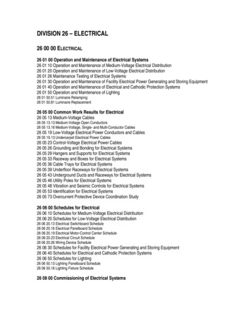
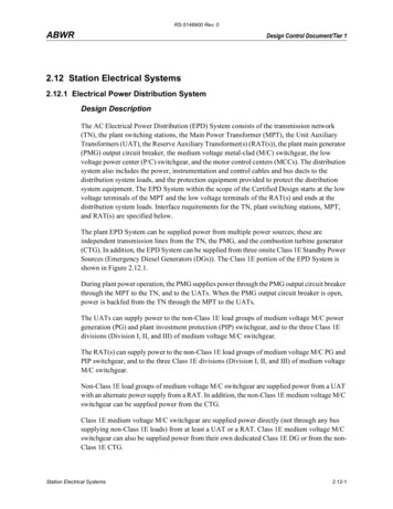
RS-5146900 Rev. 0ABWRDesign Control Document/Tier 12.12 Station Electrical Systems2.12.1 Electrical Power Distribution SystemDesign DescriptionThe AC Electrical Power Distribution (EPD) System consists of the transmission network(TN), the plant switching stations, the Main Power Transformer (MPT), the Unit AuxiliaryTransformers (UAT), the Reserve Auxiliary Transformer(s) (RAT(s)), the plant main generator(PMG) output circuit breaker, the medium voltage metal-clad (M/C) switchgear, the lowvoltage power center (P/C) switchgear, and the motor control centers (MCCs). The distributionsystem also includes the power, instrumentation and control cables and bus ducts to thedistribution system loads, and the protection equipment provided to protect the distributionsystem equipment. The EPD System within the scope of the Certified Design starts at the lowvoltage terminals of the MPT and the low voltage terminals of the RAT(s) and ends at thedistribution system loads. Interface requirements for the TN, plant switching stations, MPT,and RAT(s) are specified below.The plant EPD System can be supplied power from multiple power sources; these areindependent transmission lines from the TN, the PMG, and the combustion turbine generator(CTG). In addition, the EPD System can be supplied from three onsite Class 1E Standby PowerSources (Emergency Diesel Generators (DGs)). The Class 1E portion of the EPD System isshown in Figure 2.12.1.During plant power operation, the PMG supplies power through the PMG output circuit breakerthrough the MPT to the TN, and to the UATs. When the PMG output circuit breaker is open,power is backfed from the TN through the MPT to the UATs.The UATs can supply power to the non-Class 1E load groups of medium voltage M/C powergeneration (PG) and plant investment protection (PIP) switchgear, and to the three Class 1Edivisions (Division I, II, and III) of medium voltage M/C switchgear.The RAT(s) can supply power to the non-Class 1E load groups of medium voltage M/C PG andPIP switchgear, and to the three Class 1E divisions (Division I, II, and III) of medium voltageM/C switchgear.Non-Class 1E load groups of medium voltage M/C switchgear are supplied power from a UATwith an alternate power supply from a RAT. In addition, the non-Class 1E medium voltage M/Cswitchgear can be supplied power from the CTG.Class 1E medium voltage M/C switchgear are supplied power directly (not through any bussupplying non-Class 1E loads) from at least a UAT or a RAT. Class 1E medium voltage M/Cswitchgear can also be supplied power from their own dedicated Class 1E DG or from the nonClass 1E CTG.Station Electrical Systems2.12-1
RS-5146900 Rev. 0ABWRDesign Control Document/Tier 1The UATs are sized to supply their load requirements, during design operating modes, of theirrespective Class 1E divisions and non-Class 1E load groups. UATs are separated from theRAT(s). In addition, UATs are provided with their own oil pit, drain, fire deluge system,grounding, and lightning protection system.The PMG, its output circuit breaker, and UAT power feeders are separated from the RAT(s)power feeders. The PMG, its output circuit breaker, and UAT instrumentation and controlcircuits, are separated from the RAT(s) instrumentation and control circuits.The MPT and its switching station instrumentation and control circuits, from the switchyard(s)to the main control room (MCR), are separated from the RAT(s) and its switching stationinstrumentation and control circuits.The medium voltage M/C switchgear and low voltage P/C switchgear, with their respectivetransformers, and the low voltage MCCs are sized to supply their load requirements. M/C andP/C switchgear, with their respective transformers, and MCCs are rated to withstand faultcurrents for the time required to clear the fault from the power source. The PMG output circuitbreaker, and power feeder and load circuit breakers for the M/C and P/C switchgear, and MCCsare sized to supply their load requirements and are rated to interrupt fault currents.Class 1E equipment is protected from degraded voltage conditions.EPD System interrupting devices (circuit breakers and fuses) are coordinated to the maximumextent possible, so that the circuit interrupter closest to the fault opens before other devices.Instrumentation and control power for the Class 1E divisional medium voltage M/C switchgearand low voltage P/C switchgear is supplied from the Class 1E DC power system in the samedivision.The PMG output circuit breaker is equipped with redundant trip devices which are suppliedfrom separate, non-Class 1E DC power systems.EPD System cables and bus ducts are sized to supply their load requirements and are rated towithstand fault currents for the time required to clear the fault from its power source.For the EPD System, Class 1E power is supplied by three independent Class 1E divisions.Independence is maintained between Class 1E divisions, and also between Class 1E divisionsand non-Class 1E equipment.The only non-Class 1E loads connected to the Class 1E EPD System are the Fine MotionControl Rod Drives (FMCRDs) and the associated AC standby lighting system.There are no automatic connections between Class 1E divisions.Station Electrical Systems2.12-2
RS-5146900 Rev. 0ABWRDesign Control Document/Tier 1Class 1E medium voltage M/C switchgear and low voltage P/C switchgear and MCCs areidentified according to their Class 1E division. Class 1E M/C and P/C switchgear and MCCsare located in Seismic Category I structures, and in their respective divisional areas.Class 1E EPD System cables and raceways are identified according to their Class 1E division.Class 1E divisional cables are routed in Seismic Category I structures and in their respectivedivisional raceways.Harmonic Distortion waveforms do not prevent Class 1E equipment from performing theirsafety functions.The EPD System supplies an operating voltage at the terminals of the Class 1E utilizationequipment that is within the utilization equipment's voltage tolerance limits.An electrical grounding system is provided for (1) instrumentation, control, and computersystems, (2) electrical equipment (switchgear, distribution panels, transformers, and motors)and (3) mechanical equipment (fuel and chemical tanks). Lightning protection systems areprovided for buildings and for structures and transformers located outside of the buildings. Eachgrounding system and lightning protection system is separately grounded to the plant groundinggrid.The EPD System has the following alarms, displays and controls in the MCR:(1)Alarms for degraded voltage on Class 1E medium voltage M/C switchgear.(2)Parameter displays for PMG output voltage, amperes, watts, vars, and frequency.(3)Parameter displays for EPD System medium voltage M/C switchgear bus voltagesand feeder and load amperes.(4)Controls for the PMG output circuit breaker, medium voltage M/C switchgear feedercircuit breakers, load circuit breakers from the medium voltage M/C switchgear totheir respective low voltage P/C switchgear, and low voltage feeder circuit breakersto the low voltage P/C switchgear.(5)Status indication for the PMG output circuit breaker and the medium voltage M/Cswitchgear circuit breakers.The EDP System has the following displays and controls at the Remote Shutdown System(RSS):(1)Station Electrical SystemsParameter displays for the bus voltages on the Class 1E Divisions I and II mediumvoltage M/C switchgear.2.12-3
RS-5146900 Rev. 0ABWRDesign Control Document/Tier 1(2)Controls and status indication for the UAT, RAT(s), CTG and DG Class 1E feedercircuit breakers to the Division I and II medium voltage M/C switchgear, the loadcircuit breakers from the Class 1E Division I and II medium voltage M/C switchgearto their respective low voltage P/C switchgear, and the low voltage feeder circuitbreakers to the Class 1E Division I and II low voltage P/C switchgear.Class 1E equipment is classified as Seismic Category I.Class 1E equipment which is located in areas designated as harsh environment areas is qualifiedfor harsh environments.Interface RequirementsThe portions of the EPD System which are not part of the Certified Design shall meet thefollowing requirements:The offsite system shall consist of a minimum of two independant offsite transmission circuitsfrom the TN.Voltage variations of the offsite TN during steady state operation shall not cause voltagevariations at the loads of more than plus or minus 10% of the loads nominal ratings.The normal steady state frequency of the offsite TN shall be within plus or minus 2 hertz of 60hertz during recoverable periods of system instability.The offsite transmission circuits from the TN through and including the main step-up powertransformers and RAT(s) shall be sized to supply their load requirements, during all designoperating modes, of their respective Class 1E divisions and non-Class 1E load groups.The impedances of the main step-up power transformers and RAT(s) shall be compatible withthe interrupting capability of the plant’s circuit interrupting devices.The independence of offsite transmission power, instrumentation, and control circuits shall becompatible with the portion of the offsite transmission power, instrumentation, and controlcircuits within the DCD design scope.Instrumentation and control system loads shall be compatible with the capacity and capabilitydesign requirements of DC systems within the DCD design scope.Inspections, Tests, Analyses and Acceptance CriteriaTable 2.12.1 provides a definition of the inspections, tests, and/or analyses, together withassociated acceptance criteria, which will be undertaken for the EPD System.Station Electrical Systems2.12-4
CTGFEEDERRATFEEDERMEDIUMVOLTAGELOADDG C RCTGFEEDERUATFEEDERABWRTYP P/CP/C LOADTYP MCCTYP P/CP/C LOADTYP MCCDG B FEEDERLOW VOLTAGEDISTRIBUTIONSYSTEMTYP P/CP/C LOADTYP MCCDIV IMCC LOADMCC LOADDIV IIDIV III2.12-5Figure 2.12.1 Class 1E Electrical Power Distribution SystemDesign Control Document/Tier 1ALL LOADSARE TYPICALOF ONE ORMORE.MCC LOADRS-5146900 Rev. EDIUMVOLTAGELOADCLASS 1EDG A FEEDERStation Electrical SystemsNON-CLASS 1E
Inspections, Tests, Analyses and Acceptance CriteriaDesign Commitment1. The basic configuration for the EPD Systemis described in Section 2.12.1.Inspections, Tests, Analyses1. Inspection of the as-built system will beconducted.Acceptance Criteria1. The as-built EPD System conforms with thebasic configuration described in Section2.12.1.2. Analyses for as-built UATs exist andconclude that UAT capacity, as determinedby its nameplate rating, exceeds its analyzedload requirements, during design operatingmodes, for its Class 1E division and nonClass 1E load group.3. UATs are separated from the RAT(s).3. Inspections of the as-built UATs will beconducted.3. As-built UATs are separated from the RAT(s)by a minimum of 15.24m.4. UATs are provided with their own oil pit,drain, fire deluge system, grounding, andlightning protection systems.4. Inspections of the as-built UATs will beconducted.4. As-built UATs are provided with their own oilpit, drain, fire deluge system, grounding, andlightning protection systems.2.12-6Design Control Document/Tier 15. As-built PMG and its output circuit breaker isseparated from the RAT(s) power feeders bya minimum of 15.24m, or by walls or floors.The PMG and its output circuit breakerinstrument and control circuits are separatedfrom the RAT(s) instrumentation and controlcircuits by a minimum of 15.24m, or by wallsor floors outside the MCR, and are separatedby routing the circuits in separate racewaysinside the MCR.RS-5146900 Rev. 02. Analyses for the as-built UATs to determine2. UATs are sized to supply their loadtheir load requirements will be performed.requirements, during design operatingmodes, of their respective Class 1E divisionsand non-Class 1E load groups.5. Inspections for the as-built PMG, the PMG5. The PMG and its output circuit breaker isoutput circuit breaker, the RAT(s) and theirseparated from the RAT(s) power feeders.respective instrumentation and controlThe PMG and its output circuit breakercircuits will be conducted.instrument and control circuits are separatedfrom the RAT(s) instrumentation and controlcircuits.ABWRStation Electrical SystemsTable 2.12.1 Electric Power Distribution System
Inspections, Tests, Analyses and Acceptance CriteriaDesign CommitmentInspections, Tests, AnalysesAcceptance Criteria6. Inspections for the as-built UATs and RAT(s) 6. As-built UAT power feeders are separatedpower feeders, and instrumentation andfrom the RAT(s) power feeders by acontrol circuits will be conducted.minimum of 15.24m, or by walls or floors,except at the switchgear, where they arerouted to opposite ends of the mediumvoltage M/C switchgear. As-built UATinstrumentation and control circuits, areseparated from the RAT(s) instrumentationand control circuits by a minimum of 15.24m,or by walls or floors, except as follows: a) atthe non-Class 1E DC power sources, wherethey are routed in separate raceways, b)inside the MCR, where they are separatedby routing the circuits in separate raceways,and c) at the switchgear, where they arerouted to opposite ends of the mediumvoltage M/C switchgear and routed inseparate raceways inside the switchgear.7. The MPT and its switching stationinstrumentation and control circuits areseparated from the RAT(s) and its switchingstation instrumentation and control circuits.7. Inspections for the as-built MPT and RAT(s)and their respective switching stationinstrumentation and control circuits will beconducted.2.12-7Design Control Document/Tier 17. As-built MPT and its switching stationinstrumentation and control circuits, from theswitchyard(s) to the MCR, are separatedfrom the RAT(s) and its switching stationinstrumentation and control circuits by aminimum of 15.24m, or by walls or floors.MPT and its switching stationinstrumentation and control circuits, insidethe MCR, are separated from the RAT(s) andits switching station instrumentation andcontrol circuits by routing the circuits inseparate raceways.RS-5146900 Rev. 06. UATs power feeders, and instrumentationand control circuits are separated from theRAT(s) output power feeders, andinstrumentation and control circuits.ABWRStation Electrical SystemsTable 2.12.1 Electric Power Distribution System (Continued)
Inspections, Tests, Analyses and Acceptance CriteriaDesign CommitmentInspections, Tests, Analyses8. Medium voltage M/C switchgear, low voltage 8. Analyses for the as-built EPD System todetermine load requirements will beP/C switchgear, with their respectiveperformed.transformers, and MCCs, and theirrespective switchgear and MCC feeder andload circuit breakers are sized to supply theirload requirements.b. The PMG output circuit breaker, mediumvoltage M/C switchgear, low voltage P/Cswitchgear and MCC feeder and loadcircuit breakers are rated to interruptfault currentsa. Analyses for the as-built EPD System todetermine fault currents will beperformed.b. Analyses for the as-built EPD System todetermine fault currents will beperformed.a. Analyses for the as-built EPD Systemexist and conclude that the Class 1Eswitchgear, with their respectivetransformers, and MCC, currentcapacities exceed their analyzed faultcurrents for the time required, asdetermined by the circuit interruptingdevice coordination analyses, to clearthe fault from its power source.2.12-8Design Control Document/Tier 1b. Analyses for the as-built EPD Systemexist and conclude that the analyzedfault currents do not exceed the PMGoutput circuit breaker, and M/C, P/Cswitchgear, and MCC feeder and loadcircuit breakers interrupt capacities, asdetermined by their nameplating ratings.RS-5146900 Rev. 0a. Medium voltage M/C switchgear, lowvoltage P/C switchgear, with theirrespective transformers, and MCCs, arerated to withstand fault currents for thetime required to clear the fault from itspower source.8. Analyses for the as-built EPD System existand conclude that the capacities of the Class1E switchgear, P/C transformers, MCCs, andtheir respective feeder and load circuitbreakers, as determined by their nameplateratings, exceed their analyzed loadrequirements.9.9.9.Acceptance CriteriaABWRStation Electrical SystemsTable 2.12.1 Electric Power Distribution System (Continued)
Inspections, Tests, Analyses and Acceptance CriteriaDesign Commitment10. Class 1E equipment is protected fromdegraded voltage conditions.Inspections, Tests, Analyses10.10.a. Analyses for the as-built EPD System todetermine the trip conditions fordegraded voltage conditions will beperformed.11. Analyses for the as-built EPD System todetermine circuit interrupting devicecoordination will be performed.13. The PMG output circuit breaker is equippedwith redundant trip devices which aresupplied from separate non-Class 1E DCpower systems.b. As-built Class 1E feeder breakers frompreferred offsite power to the Class 1EM/C switchgear trip when a degradedvoltage condition exists.11. Analyses for the as-built EPD System existand conclude that, to the maximum extentpossible, the analyzed circuit interrupterclosest to the fault will open before otherdevices.12. A test signal exists in only the Class 1Edivision under test.13. Tests of the as-built PMG output circuit13. A test signal exists in only the circuit underbreaker will be conducted by providing a testtest.signal in only one trip circuit at a time.2.12-9Design Control Document/Tier 112. Instrumentation and control power for Class 12. Tests of the as-built Class 1E medium andlow voltage switchgear will be conducted by1E divisional medium voltage M/Cproviding a test signal in only one Class 1Eswitchgear and low voltage P/C switchgear isdivision at a time.supplied from the Class 1E DC powersystem in the same division.a. Analyses for the as-built EPD Systemexist and conclude that the Class 1Epreferred offsite power feeder breakersto the Class 1E M/C switchgear will tripbefore Class 1E loads experiencedegraded voltage conditions exceedingthose voltage conditions for which theClass 1E equipment is qualified.RS-5146900 Rev. 0b. Tests for each as-built Class 1E M/Cswitchgear will be conducted byproviding a simulated degraded voltagesignal.11. EPD System interrupting devices (circuitbreakers and fuses) are coordinated to themaximum extent possible, so that the circuitinterrupter closest to the fault opens beforeother devices.Acceptance CriteriaABWRStation Electrical SystemsTable 2.12.1 Electric Power Distribution System (Continued)
Inspections, Tests, Analyses and Acceptance CriteriaDesign CommitmentInspections, Tests, AnalysesAcceptance CriteriaABWRStation Electrical SystemsTable 2.12.1 Electric Power Distribution System (Continued)14. EPD System cables and bus ducts are sized 14. Analyses for the as-built EPD System cables 14. Analyses for the as-built EPD System existto supply their load requirements.and bus ducts will be performed.and conclude that cable and bus ductcapacities, as determined by cable and busduct ratings, exceed their analyzed loadrequirements.15. EPD System cables and bus ducts are rated 15. Analyses for the as-built EPD System todetermine fault currents will be performed.to withstand fault currents for the timerequired to clear its fault from its powersource.16.16.17. Class 1E medium voltage M/C switchgearand low voltage P/C switchgear and MCCsare identified according to their Class 1Edivision.17. Inspections of the as-built EPD SystemClass 1E M/C and P/C switchgear andMCCs will be conducted.18. Class 1E M/C and P/C switchgear andMCCs are located in Seismic Category Istructures and in their respective divisionalareas.18. Inspections of the as-built Class 1E M/C and 18. As-built Class 1E M/C and P/C switchgear,P/C switchgear and MCCs will be conducted.and MCCs are located in Seismic Category Istructures and in their respective divisionalareas.a. Tests on the as-built EPD System will beconducted by providing a test signal inonly one Class 1E division at a time.a. A test signal exists in only the Class 1Edivision under test in the EPD System.b. Inspections of the as-built EPD SystemClass 1E divisions will be conducted.b. In the EPD System, physical separationor electrical isolation exists betweenClass 1E divisions. Physical separationor electrical isolation exists betweenthese Class 1E divisions and non-Class1E equipment.17. As-built Class 1E M/C and P/C switchgear,and MCCs are identified according to theirClass 1E division.Design Control Document/Tier 12.12-1016. For the EPD System, Class 1E power issupplied by three independent Class 1Edivisions. Independence is maintainedbetween Class 1E divisions, and betweenClass 1E divisions and non-Class 1Eequipment.RS-5146900 Rev. 015. Analyses for the as-built EPD System existand conclude that cables and bus ducts willwithstand the analyzed fault currents for thetime required, as determined by the circuitinterrupting device coordination analyses, toclear the analyzed faults from their powersources.
Inspections, Tests, Analyses and Acceptance CriteriaDesign CommitmentInspections, Tests, AnalysesAcceptance Criteria19. Class 1E EPD System cables and raceways 19. Inspections of the as-built Class 1E EPDare identified according to their Class 1ESystem cables and raceways will bedivision.conducted.19. As-built Class 1E EPD System cables andraceways are identified according to theirClass 1E division.20. Class 1E divisional cables are routed inSeismic Category I structures and in theirrespective divisional raceways.20. As-built Class 1E divisional cables are routedin Seismic Category I structures and in theirrespective divisional raceways.20. Inspection of the as-built Class 1E EPDSystem divisional cables and raceways willbe conducted.21. Harmonic Distortion waveforms do not21. Analyses for the as-built EPD System toprevent Class 1E equipment from performingdetermine harmonic distortions will betheir safety functions.performed.21. Analyses for the as-built EPD System existand conclude that harmonic distortionwaveforms do not exceed 5% voltagedistortion on the Class 1E EPD System.22.22.a. Analyses for the as-built EPD Systemexist and conclude that the analyzedoperating voltage supplied at theterminals of the Class 1E utilizationequipment is within the utilizationequipment's voltage tolerance limits, asdetermined by their nameplate ratings.b. Type tests at manufacturer's shop will beperformed for the operating voltagerange of the Class 1E electrical equipment.b. Manufacturer's type test reports existand conclude that the operating range iswithin the tested voltage range for theClass 1E electrical equipment.c.System preoperational and Startup testswill be conducted of the as-built Class 1EEPD System.c.The test voltages from preoperationaltest reports are compared againstsystem voltage analysis of the as-builtClass 1E EPD system. The results ofcomparison conclude that the availablevoltage is within the operating range forthe as-installed equipment.2.12-11Design Control Document/Tier 1a. Analyses for the as-built EPD System todetermine voltage drops will beperformed.RS-5146900 Rev. 022. The EPD System supplies an operatingvoltage at the terminals of the Class 1Eutilization equipment that is within theutilization equipment's voltage tolerancelimits.ABWRStation Electrical SystemsTable 2.12.1 Electric Power Distribution System (Continued)
Inspections, Tests, Analyses and Acceptance CriteriaDesign CommitmentInspections, Tests, AnalysesAcceptance CriteriaABWRStation Electrical SystemsTable 2.12.1 Electric Power Distribution System (Continued)23. Inspections of the as-built EPD System plant 23. The as-built EPD System instrumentation,23. An electrical grounding system is providedGrounding and Lightning Protection Systemscontrol, and computer grounding system,for (1) instrumentation, control, andwill be conducted.electrical equipment and mechanicalcomputer systems, (2) electrical equipmentequipment grounding system, and lightning(switchgear, distribution panels,protection systems provided for buildingstransformers, and motors) and (3)and for structures and transformers locatedmechanical equipment (fuel and chemicaloutside of the buildings are separatelytanks). Lightning protection systems aregrounded to the plant grounding grid.provided for buildings and for structures andtransformers located outside of the buildings.Each grounding system and lightningprotection system is separately grounded tothe plant grounding grid.25. RSS displays and controls provided for theEPD System are as defined in Section2.12.1.RS-5146900 Rev. 024. MCR alarms, displays and controls provided 24. Inspections will be conducted on the MCRfor the EPD System are as defined in Sectionalarms, displays and controls for the EPD2.12.1.System.24. Displays and controls exist or can beretrieved in the MCR as defined in Section2.12.1.25. Inspections will be conducted on the as-built 25. Displays and controls exist or can beRSS displays and controls for the EPDretrieved on the RSS as defined in Section2.12.1.System.Design Control Document/Tier 12.12-12
RS-5146900 Rev. 0ABWRDesign Control Document/Tier 12.12.2 Unit Auxiliary TransformerNo entry. Covered in Section 2.12.1.Station Electrical Systems2.12-13
RS-5146900 Rev. 0ABWRDesign Control Document/Tier 12.12.3 Isolated Phase BusNo entry. Covered in Section 2.12.1.Station Electrical Systems2.12-14
RS-5146900 Rev. 0ABWRDesign Control Document/Tier 12.12.4 Nonsegregated Phase BusNo entry. Covered in Section 2.12.1.Station Electrical Systems2.12-15
RS-5146900 Rev. 0ABWRDesign Control Document/Tier 12.12.5 Metal Clad SwitchgearNo entry. Covered in Section 2.12.1.Station Electrical Systems2.12-16
RS-5146900 Rev. 0ABWRDesign Control Document/Tier 12.12.6 Power CenterNo entry. Covered in Section 2.12.1.Station Electrical Systems2.12-17
RS-5146900 Rev. 0ABWRDesign Control Document/Tier 12.12.7 Motor Control CenterNo entry. Covered in Section 2.12.1.Station Electrical Systems2.12-18
RS-5146900 Rev. 0ABWRDesign Control Document/Tier 12.12.8 Raceway SystemNo entry. Covered in Section 2.12.1.Station Electrical Systems2.12-19
RS-5146900 Rev. 0ABWRDesign Control Document/Tier 12.12.9 Grounding WireNo entry. Covered in Section 2.12.1.Station Electrical Systems2.12-20
RS-5146900 Rev. 0ABWRDesign Control Document/Tier 12.12.10 Electrical Wiring PenetrationDesign DescriptionElectrical penetrations are provided for electrical cables passing through the primarycontainment.Electrical penetrations are classified as safety-related.Electrical penetrations are protected against currents that are greater than their continuouscurrent rating.Electrical penetrations are classified as Seismic Category I.Divisional electrical penetrations only contain cables of one Class 1E division. Independenceis provided between divisional electrical penetrations and also between divisional electricalpenetrations and penetrations containing non-Class 1E cables.Electrical penetrations are qualified for a harsh environment.Inspections, Tests, Analyses and Acceptance CriteriaTable 2.12.10 provides a definition of the inspections, tests, and/or analyses, together with theassociated acceptance criteria, which will be undertaken for the Electrical Wiring Penetrations.Station Electrical Systems2.12-21
Inspections, Tests, Analyses and Acceptance CriteriaDesign Commitment1. The basic configuration of the ElectricalWiring Penetration is described in Section2.12.10.Inspections, Tests, Analyses1. Inspections of the as-built Electrical WiringPenetration will be conducted.2. Electrical penetrations are protected against 2. Analyses for the as-built electricalcurrents that are greater than theirpenetrations and protective features will becontinuous current ratings.performed.Acceptance CriteriaABWRStation Electrical SystemsTable 2.12.10 Electrical Wiring Penetration1. The as-built Electrical Wiring Penetrationconforms with the basic configurationdescribed in Section 2.12.10.RS-5146900 Rev. 02. Analyses for the as-built electricalpenetrations and protective features existand conclude either 1) that the maximumcurrent of the circuits does not exceed thecontinuous current rating of the penetration,or 2) that the circuits have redundantprotective devices in series and that theredundant protection devices arecoordinated with the penetration's rated shortcircuit thermal capacity data and preventcurrent from exceeding the continuouscurrent rating of the electrical penetrations.3. Divisional electrical penetrations only contain 3. Inspections of the as-built divisional electrical 3. As-built divisional electrical penetrations onlycables of one Class 1E division.penetrations will be conducted.contain cables of one Class 1E division.4. Independence is provided between divisional 4. Inspections of the as-built electricalpenetrations will be conducted.electrical penetrations and betweendivisional electrical penetrations andpenetrations containing non-Class 1Ecables.4. Physical separation exists between as-builtdivisional electrical penetrations. Physicalseparation exists between these divisionalelectrical penetrations and penetrationscontaining non-Class 1E cables.Design Control Document/Tier 12.12-22
RS-5146900 Rev. 0ABWRDesign Control Document/Tier 12.12.11 Combustion Turbine GeneratorDesign DescriptionThe Combustion Turbine Generator (CTG) is a self-contained unit with its own supportingauxiliary systems. The CTG functions as an alternate AC power source.The CTG is classified as non-safety-related.The CTG can supply power to the non-Class 1E plant investment protection (PIP) busses or tothe Class 1E divisional busses. The CTG capacity to supply power is at least as large as thecapacity of an emergency diesel generator (DG). The CTG is located outside the ReactorBuilding.The CTG has the following displays and controls in the main control room (MCR):(1)Paramete
generation (PG) and plant investment protection (PIP) switchgear, and to the three Class 1E divisions (Division I, II, and III) of medium voltage M/C switchgear. The RAT(s) can supply power to the non-Class 1E load groups of medium voltage M/C PG and PIP switchgear, and to the three Class