Transcription
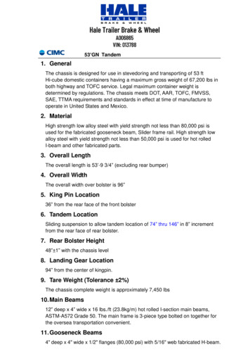
Hale Trailer Brake & WheelA006865VIN: 01378853’GN Tandem1. GeneralThe chassis is designed for use in stevedoring and transporting of 53 ftHi-cube domestic containers having a maximum gross weight of 67,200 lbs inboth highway and TOFC service. Legal maximum container weight isdetermined by regulations. The chassis meets DOT, AAR, TOFC, FMVSS,SAE, TTMA requirements and standards in effect at time of manufacture tooperate in United States and Mexico.2. MaterialHigh strength low alloy steel with yield strength not less than 80,000 psi isused for the fabricated gooseneck beam, Slider frame rail. High strength lowalloy steel with yield strength not less than 50,000 psi is used for hot rolledI-beam and other fabricated parts.3. Overall LengthThe overall length is 53’-9 3/4” (excluding rear bumper)4. Overall WidthThe overall width over bolster is 96”5. King Pin Location36” from the rear face of the front bolster6. Tandem LocationSliding suspension to allow tandem location of 74” thru 146” in 8” incrementfrom the rear face of rear bolster.7. Rear Bolster Height48” 1” with the chassis level8. Landing Gear Location94” from the center of kingpin.9. Tare Weight (Tolerance 2%)The chassis complete weight is approximately 7,450 lbs10. Main Beams12” deep x 4” wide x 16 lbs./ft (23.8kg/m) hot rolled I-section main beams,ASTM-A572 Grade 50. The main frame is 3-piece type bolted on together forthe oversea transportation convenient.11. Gooseneck Beams4" deep x 4" wide x 1/2" flanges (80,000 psi) with 5/16" web fabricated H-beam.
53’GN Tandem120” from the rear face of the front bolster to the end of the gooseneck. 3-1/8”plus 0”, minus 1/16” distance between the top of the main frame and the top ofthe gooseneck.12. Cross Members3/16” (4.5mm) thick x 2 1/2” wide x 9” height.3/16” (4.5mm) thick x 3” wide x 5 1/4” height cross members with integratedtriangular gussets over sliding bogie.1/8” (3mm) fabricated Profiled bar type diagonal brace.13. Upper Coupler Assemblya) 1/4” thick pick up plate will be installed with continuous welding along theentire perimeter.b) The King Pin is of 2” diameter “L” series or Cruciform series, S.A.E.standard J700B and certified per AAR. Forged steel alloy heat treated tosurface hardness of Brinell 380 to 420.c) 2” diameter water drain hole.d) 1/4” thick fabricated wide channel type king pin supporter.e) 3/16” thick gooseneck crossmembers behind the pick up plate.King pin supplier: Holland or JOST.14. Front Bolster7-3/8” wide x 7-3/4” high, 1/4” thick open section is fabricated by hi-tensileminimum Grade 50 steel, it’s rear web shall be tapered forward at the topapproximately 2-3/8” x 45 degrees to provide a container gather in astevedoring operation. Front bolster provides full recessing of lights, air andelectrical connectors, and the connectors will be located in roadside for easyoperation.Two 3/16” thick triangular wing plates are welded on each side between themain rail and front bolster to reinforce the bolster.Front Bolster corner castings are provided at each end.15. Front Locking PinsThe front locking pins are the Schulz FB99HL-JBH-LH/RH.16. Rear Bolster7 1/2” wide x 1/4” thick top plate with 6 4/5” wide x 8” deep x 3/16” thick “U”type bottom channel, assembly with cantilevered twist locks each end at 89”centers. 5/16” x 7/8” high light protector each side. The rear bolster will bebolted on the main frame for easy maintenance. Two reinforcement gussetsare bolted between the main rail and rear bolster on each side.17. Twist LocksRear twist locks are Schulz 905-177-000-45-LP-CS-JBH &
53’GN Tandem905-177-000-45-LP-RS-JBH.18. DOT BumperDrop type meets DOT requirements. 3/16” x 4” x 4” square tube step guardwith taper “H” section vertical member. Drop bumper to be 22” above groundand 94” long with recess for conspicuity treatment. The round corners areprovided at each end of step guard for blow shedding capabilities. The bumperis bolted on the rear bolster.19. Landing GearJOST A400.T18.17, 17” travel landing gear is used. 10 bolt, two speed vertical,tubular legs with low profile shoe and solid axle. Roadside crank handle.20. Landing Gear Support BracketsLanding gear boxes are fabricated of 1/4” thick grade 50 steel and bolted tothe main frame with 5/8” grade 8 Hex head bolts. There are 1/4” thickstiffeners both inside and outside of the landing gear box. Min.1/4” thick anglebrace to support the landing gear. The landing leg is designed to bend orbreak before the landing leg bracket when a force occurs lengthwise to thechassis. 4” channel cross brace at 5 lbs/ft.21. Tandem & SuspensionHolland Z frame (ZFC02-1H000 series), 4 - Pin spring loaded release with2-leaf high arch 324-01 spring (11,000 lb. capacity each). Slider frame will befabricated by CIMC under approval of supplier.Four-pin slider with substantial positive end stops to prevent overextending theslider or separating tandem from chassis frame. The tandem sliding rangeassure that the forward slider setting allows the distance between the centerline of the king pin and center line of the rear axle to be less than 40' (12.2m).The slider positioning holes in the main rail are reinforced on the outside withminimum 1/4" (6mm) thick doubler plates.Slider Handle: The slider handle shall be located in front of the tandem axleand should be mounted in such a fashion to protect the slider handle frombeing damaged during normal operating requirements. The handle in thefully retracted position should extend beyond the chassis main rail by at least 4inches. At no time during the operation of the slider handle should there be aclose clearance between the handle and any other component of the chassis.22. Axles5” round axles with 25,000 lbs capacity, “N” spindle, 77-1/2” track.16-1/2” x 7” FMSI 4515 Q Brake, Crest XL Linings, Stemco B-Lock brake shoe.Stemco Pro-Torq Nut P/N 447-4743.Supplier: Saf-holland
53’GN Tandem23. BearingsA) Cone: HM218248 and HM212049 inner and outer cone.B) Cup: HM218210 and HM212011 inner and outer cup.Supplier: Stemco.24. Slack AdjustersStemco Crewson “Auto Check” 28 spline 6” automatic slack adjuster#MB72106S.25. SealsA) Stemco Guardian HP Seal P/N 307-0743.B) Mobilith SHC 007 Synthetic Semi-Fluid Grease.C) Stemco Sentinel hub cap P/N 358-4009.26. Hub and Drum10-stud hub-piloted, 285.75mm bolt circle, cast steel hub completed with nutsfor ferrous dual disc wheels with 220mm bore. 16 ½” x 7” cast iron outboardmounted brake drums.Maker: KIC lightweight hub and drum assembly.27. Wheels22.5 x 8.25, 10-Hole hub-piloted (color white), 285.75mm Bolt Circle, 26mmbolt hole diameter, 220mm bore, 5 hand holes. Assembly with Standard valveTR572.Maker: Accuride28. Tires11R22.5, 14 ply range (G) tubeless type without customer’s logo.Maker: GT Radial29. Brake Systema)b)c)d)WABCO 2S/1M ABS brake system is used.Two (2) Evolution tanks. (Capacity 1,488 cu-in each)Air line: color coded 3/8” for control line and 1/2” for supply lineBrake chamber: TSE Omnibrake Model 3030TL3 30-30 long strokebrake chambers.e) Gladhand: Phillips 12-49064/084 cast steel gladhand.30. Electrical Systema) 12 volt lighting system with Phillips QCS2 wiring harness, for ABSsystem.Electric harness will be made of three sections. Front section will extend
53’GN Tandemfrom 7-way receptacle and end just ahead of the upper coupler, A 12gauge jumper will be installed. Middle section will extend from the uppercoupler to the rear bolster. Rear section will provide leads for lights in therear bolster. A waterproof plug will be used to connect front harness,middle harness and rear bolster harness. Middle harness will allow forenough extra harness at the rear to allow the plug connection to bestored inside the rear bolster to protect it from damage and moisture.Access to the plug connection must be accessible throughout the taillighthole. A minimum of 10 inches of excess harness will be provided aheadof the king pin area and retained inside the front bolster. Lead wires toABS wheel sensors are to be covered by protective loom. SAE colorcode is used to identify wires.b) 4” Stop/Turn/Tail LED lamp: Optronics STL13RFMB.c) 3/4” Front marker/clearance LED lamp: Optronics MCL11SAKBd) 3/4” Mid marker LED lamp: Optronics MCL11SAKBe) 3/4” Rear marker/clearance LED lamp: Optronics MCL11SRKBf) 3/4” ID LED lamp: Optronics MCL11SRKBg) 3/4” ABS warning LED lamp: Optronics MCL11SAKBh) LED License lamp: Optronics LPL12CKMBi) Receptacle: Phillips 16-7242, with solid pinsj) Reflector: Peterson 489A/R or similar type4” LED lights will be connected to hard shell connectors with locking. Thepigtail is combined into the license light and 3/4” LED clearance lights withmale bullet connectors for harness connection.4” LED lights will be mounted by stainless steel rivets.Mounting of the stop and turn lights should be from inside the bolster toeliminate security ring and theft. Provide bolt on access panel to facilitatechanging lights. Provide drawings prior to start of build.31. HubodometerEach unit shall be equipped with a Hubodometer, to be located on theroadside of rear axle hub.Supplier: Stemco32. Registration HolderThe registration holder is to be mounted a minimum of 60” and a maximum of72” back from the centerline of the landing gear with stainless steel rivets.Registration cover is attached to the base with a cable.Supplier: Optronics DH55Y.
53’GN Tandem33. Mud Flaps24” x 24” "Anti-sail" rubber flap mounted on slider box, with etched UP Shield.No more than 8” ground clearance. Comply with DOT requirements.Maker: New life Transportation Parts34. PaintingAfter surface preparation, surface will be coated with marine paint of thefollowing specifications.E-coat primer (minimum 20μm).Supplier: PPGPowder coating topcoat (minimum 60μm). Color UPRR Yellow.Supplier: Valspar or PPG.The frame painting has 7 years warranty.The spring hanger pipes shall be internally sprayed after assembly withwax-based coating, color: black.35. MarkingComplete Decal package installed by CIMC @ UP design to be furnished.Decals warrant for seven (7) years minimum against peeling, cracking orfading. Decals will be made of durable vinyl material, using inks andadhesives recommended by the supplier of the vinyl material.Marking diagram must be approved prior to start of build.36. Conspicuity TapeInstalled per Federal regulations.DISCLAIMERSpecifications are believed to be correct, but may contain errors and/or omissions. Photographs are the representative of the subject equipment but may not be identical.Equipment availability, prices and specifications are subject to change without notice.
a) 1/4” thick pick up plate will be installed with continuous welding along the entire perimeter. b) The King Pin is of 2” diameter “L” series or Cruciform series, S.A.E. standard J700B and certified per AAR. Forged steel alloy heat treated to surface hardnes