Transcription
Maintenance Manual 5ASingle-Reduction Differential CarriersSingle Rear Drive Axles, Rear-Rear Tandem DriveAxles and Front Drive Steer AxlesRevised 02-18
Service NotesAbout This ManualThis manual provides instructions for the Meritor MX, RS, RT and RFSeries axles and 59000 Series angle drive carrier.Before You Begin1.Read and understand all instructions and procedures beforeyou begin to service components.2.Read and observe all Warning and Caution hazard alertmessages in this publication. They provide information that canhelp prevent serious personal injury, damage to components,or both.3.Follow your company’s maintenance and service, installation,and diagnostics guidelines.4.Use special tools when required to help avoid serious personalinjury and damage to components.If Tools and Supplies are Specified inThis ManualContact Meritor’s Commercial Vehicle Aftermarket at888-725-9355.Hazard Alert Messages and TorqueSymbolsWARNINGA Warning alerts you to an instruction or procedure that youmust follow exactly to avoid serious personal injury anddamage to components.CAUTIONA Caution alerts you to an instruction or procedure that youmust follow exactly to avoid damage to components.@ This symbol alerts you to tighten fasteners to a specified torquevalue.How to Obtain Additional Maintenance,Service and Product InformationVisit Literature on Demand at meritor.com to access and orderadditional information.Contact the Meritor OnTrac Customer Call Center at866-668-7221 (United States and Canada); 001-800-889-1834(Mexico); or email OnTrac@meritor.com.Information contained in this publication was in effect at the time the publication wasapproved for printing and is subject to change without notice or liability. Meritor HeavyVehicle Systems, LLC, reserves the right to revise the information presented or todiscontinue the production of parts described at any time.Meritor Maintenance Manual 5A (Revised 02-18)
Contentspg. 1Section 1: Exploded Viewspg. 26Exploded ViewsSingle-Reduction Differential Carrier5678910121314171821222325Section 2: IntroductionDescriptionStandard Single-Reduction Carriers Without DifferentialLockSingle-Reduction Carriers with Driver-Controlled MainDifferential Lock (DCDL)Axle Models Covered in This ManualStall-Testing Can Damage a Drive AxleUse of Traction ChainsSection 3: Removal and DisassemblyRemovalAxle ShaftsAxle Shaft Removal MethodsAxle Shafts from the Axle HousingDifferential Carrier from the Axle HousingMeasure Ring Gear BacklashDifferential and Ring Gear from the CarrierDisassemblyDifferential and Ring Gear AssemblyRemovalDrive Pinion and Bearing Cage from the CarrierDisassemblyDrive Pinion and Bearing Cage272830323436383941434445Section 4: Prepare Parts for AssemblyClean, Dry and Inspect PartsClean and Inspect YokesClean Ground and Polished PartsClean Rough PartsClean Axle AssembliesDrying Parts After CleaningPrevent Corrosion on Cleaned PartsInspect PartsRepair or Replace PartsWelding on Axle HousingsDo Not Bend or Straighten a Damaged Drive Axle HousingRemoving Fasteners Secured with AdhesiveNew Fasteners with Pre-Applied AdhesiveOriginal or Used FastenersMeritor Specification 2297-T-4180 Adhesive in theDifferential Bearing BoresCarrier-to-Housing Joint Sealing ProcedureGeneral Yoke and U-Joint ReassemblyIdentificationGear Sets474849525356585960646566Section 5: Assembly and InstallationAssemblyDrive Pinion, Bearings and Bearing CageInstallationOne-Piece Spigot Bearing on the Drive Pinion with a SnapRingOne-Piece Spigot Bearing on the Drive Pinion Without aSnap RingTwo-Piece Spigot Bearing on the Drive PinionDrive PinionAdjustmentPinion Bearing PreloadShim Pack Thickness for a New Drive PinionInstallationDrive Pinion, Bearing Cage and Shim Pack into the CarrierTight Fit Yokes and POSE SealAny Type Yoke with a Unitized Pinion Seal (UPS)Clean, Inspect and Install the Yoke After Installing aUnitized Pinion SealAny Type Yoke with a Multiple Lip Seal (MLS)AssemblyMain Differential and Ring Gear AssemblyInspectionDifferential Gears Rotating ResistanceInstallationDifferential and Ring Gear AssemblyAdjustmentDifferential Bearing PreloadRing Gear RunoutRing Gear BacklashGear Set Tooth Contact Patterns (Backlash)InstallationThrust Screw (If Equipped)Differential Carrier into the Axle HousingSection 6: Driver-Controlled MainDifferential LockDescriptionVehicle TowingRemovalDifferential Carrier from the Axle HousingAxle Setup for DCDL DisassemblyDCDL Assembly Manual Engaging MethodsDifferential and Gear AssemblyInstallationDCDL Assembly into the CarrierDifferential Lock Assembly Cover PlatesCarrier into the Axle HousingCheck the Differential Lock
Contentspg. 6768DCDL Driver Caution Alert LabelDriver Instruction Information AvailableSection 7: LubricationSpecifications70Section 8: Specifications71FastenersAmerican Standard FastenersMetric FastenersTorque Specifications7678Section 9: AdjustmentSection 10: Special Tools81SpecificationsCarrier Repair StandHow to Make a Yoke BarUnitized Pinion Seals and Seal DriversMultiple Lip Seals (MLS) and Seal Drivers82Section 11: Vehicle Towing Instructions79869092939495Type of AxleSingle Axle with DCDL — Screw-In (Threaded) ShiftAssembly, or Tandem Axle with DCDL — Screw-In(Threaded) Shift Assembly and with Inter-AxleDifferential (IAD)Single Axle with DCDL — Bolt-On Shift Assembly, orTandem Axle with DCDL — Bolt-On Shift Assembly andwith Inter-Axle Differential (IAD)Single Axle Without DCDL or Tandem Axle Without DCDLand with Inter-Axle Differential (IAD)Section 12: DiagnosticsTroubleshootingVehicle Will Not MoveDifferential Making NoiseOil LeakContaminated Lubricant Found During PreventiveMaintenancepg.
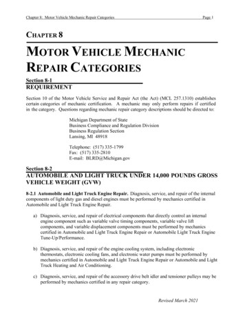
1 Exploded ViewsExploded Views1 Exploded ViewsSingle-Reduction Differential CarrierFigure on1Drive Pinion Nut*32Differential Bearing Cap Capscrews2Drive Pinion Washer*33Washers3Input Yoke or Flange*34Differential Bearing Caps3ADeflector56Differential Bearing Cap Capscrews4POSE Seal57Washers5Triple-Lip or Main Seal58Differential Bearing Cap6Outer Bearing Cone59Carrier7Inner Bearing Cup60Adjusting Ring8Sensor Switch619Sensor Switch LocknutAdjusting Ring Cotter Pin, Spring Pin (Spirol )or Capscrews29Lock Plate Capscrews*62Thrust Screw Jam Nut*30Lock Plate Washers*63Thrust Screw*31Adjusting Ring Lock Plate64Snap RingMeritor Maintenance Manual 5A (Revised 02-18)1
1 Exploded ViewsItemDescription65Spigot Bearing66Drive Pinion67Pinion Inner Bearing Cone68Pinion Inner Bearing Cup69Pinion Bearing Spacer70Shims71Drive Pinion Bearing Cage72Bearing Cage Capscrew73Washer74Clip and Cable Holder* Some Meritor carriers do not have these parts.2Meritor Maintenance Manual 5A (Revised 02-18)
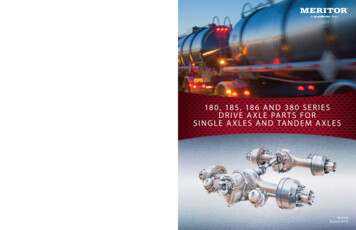
1 Exploded ViewsFigure 1.220 A1918 A1518 B171620141213647811762122287726 2523 ItemDescriptionItemDescription10Plug*15Spring Retaining Pin11Right-Hand Adjusting Ring16Air Cylinder Washer or Silastic*12Shift Fork17Air Cylinder Tube13Shift Shaft Spring18AScrew-In Differential Lock Cylinder14Shift Shaft18BCylinder CoverMeritor Maintenance Manual 5A (Revised 02-18)3
1 Exploded ViewsItemDescriptionItemDescription19Manual Actuation Capscrew76Washer20Cylinder Cover Plug77Bolt20ACover Plug Gasket78Screw-In Cover21Cylinder Cover Capscrews22Cylinder Cover Washers23Cylinder Cover Plug23ACover Plug Gasket24Cylinder Cover Copper Gasket25Piston O-Ring26Piston27Shift Collar28Shift Fork Pins35Differential Side Gears36Differential Pinion Thrust Washers37Differential Pinions38Differential Side Gears39Differential Side Gear Thrust Washers40Differential Bearing Cone41Differential Bearing Cup42Thru Bolt43Differential Case Bolts*44Differential Case Washers45Main Differential Case Assembly46Differential Spider47Ring Gear and Case Half Bolts or Rivets*48Ring Gear49Flange Case Half50Case Half Washers51Case Half Nuts*52Left-Hand Differential Bearing Cone53Left-Hand Differential Bearing Cup54Thru Bolt Washer55Thru Bolt Nut64Snap Ring75Bolt-On Cover4Meritor Maintenance Manual 5A (Revised 02-18)* Some Meritor carriers do not have these parts.
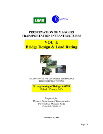
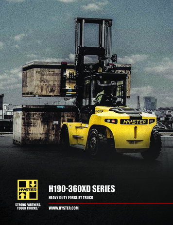
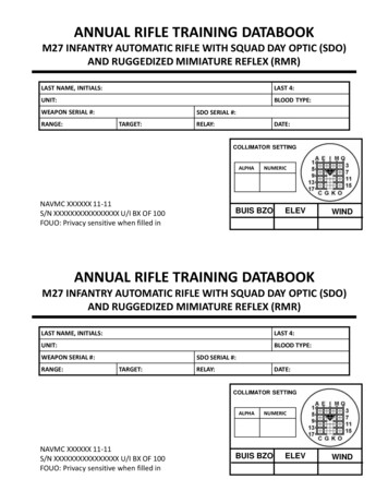
2 IntroductionDescription2 IntroductionStandard Single-Reduction Carriers WithoutDifferential LockMeritor single-reduction standard carriers are used in most Meritorsingle axles, rear of tandem axles and front drive steer axles.Figure 2.1.The single-reduction carriers are front mounted into the axlehousing. These carriers have a hypoid drive pinion and ring gear setand bevel gears in the differential assembly.Single-Reduction Carriers withDriver-Controlled Main Differential Lock(DCDL)Meritor single-reduction carriers with driver-controlled maindifferential lock (DCDL) have the same type of gears and bearings asthe standard-type carriers. Figure 2.2. The differential lock isoperated by an air-actuated shift assembly that is mounted on thecarrier.앫 When the differential lock is activated, the shift collar movesalong the splines of the axle shaft toward the differential case.A straight roller bearing or spigot is mounted on the head of thedrive pinion. All other bearings in the carrier are tapered rollerbearings.앫 When the splines on the collar are engaged with splines on thedifferential case, the axle shafts and differential assembly arelocked together.When the carrier operates, there is normal differential actionbetween the wheels at all times.앫 When the carrier operates with the DCDL in the locked position,there is no differential action between the wheels.Figure 2.1앫 When the carrier is operated in the unlocked position, there isnormal differential action between the wheels at all times.Figure 2.211827234651000982c1002981c1212345678TAPERED ROLLER BEARINGSCARRIERSTRAIGHT ROLLER BEARINGTAPERED ROLLER BEARINGBEVEL DIFFERENTIAL GEARSHOUSINGTAPERED ROLLER BEARINGHYPOID DRIVE PINION AND RING GEARBOLT-IN STYLESCREW-IN OR THREADED STYLESTANDARD CARRIER WITH DIFFERENTIAL LOCK (DCDL)Figure 2.2Figure 2.1Meritor Maintenance Manual 5A (Revised 02-18)5
2 IntroductionAxle Models Covered in This ManualTable D: Front Drive Steer AxlesTable A, Table B, Table C and Table D list the axle models covered inthis manual. For other models (non-MX, RS, RT and RF Series), referto Maintenance Manual 5, Single-Reduction Differential Carriers. Toobtain this publication, refer to the Service Notes page on the frontinside cover of this RF-21-155RF-23-185MX-23-160RF-21-156Table A: RS and MS Series Single Drive -14X(hypoid)Table B: Bus and Coach Application Single Drive 1143Table C: Rear Axle of Tandem MT-44-14X(hypoid)Meritor Maintenance Manual 5A (Revised 02-18)MX-23-160RStall-Testing Can Damage a Drive AxleStall-testing is a procedure used to troubleshoot transmissions,evaluate vehicle performance, and test the service and park brakes.During stall-testing, or any similar procedure, the drive axle inputreceives multiplied torque, which can exceed the specified torquerating. Excessive torque can damage a drive axle, which will affectaxle performance and component life. A drive axle damaged bystall-testing will void Meritor’s warranty.Call the Meritor OnTrac Customer Call Center at 866-668-7221 ifyou have questions regarding stall-testing.Use of Traction ChainsMeritor recommends that if you are using traction chains, youshould install chains on both tires on each side of all drive axles onthe vehicle.
3 Removal and DisassemblyHazard Alert Messages3 Removal and DisassemblyRead and observe all Warning and Caution hazard alert messages inthis publication. They provide information that can help preventserious personal injury, damage to components, or both.WARNINGTo prevent serious eye injury, always wear safe eye protectionwhen you perform vehicle maintenance or service.Park the vehicle on a level surface. Block the wheels toprevent the vehicle from moving. Support the vehicle withsafety stands. Do not work under a vehicle supported only byjacks. Jacks can slip and fall over. Serious personal injury canresult.Use a brass or synthetic mallet for assembly and disassemblyprocedures. Do not hit steel parts with a steel hammer. Piecesof a part can break off. Serious personal injury and damage tocomponents can result.Observe all warnings and cautions provided by the pressmanufacturer to avoid damage to components and seriouspersonal injury.앫 If the tools are not available when you remove the axleshaft: Follow procedures for using the Brass Drift Method or theAir Vibration Method.ToolPart NumberManufacturerAxle ShaftRemoverK-1280Kiene DieselAccessories, Inc.Axle Stud ConePlier7077SPX OTCBrass Drift MethodWARNINGDo not strike the round driving lugs on the flange of an axleshaft. Pieces can break off and cause serious personal injury.1.Hold a 1-1/2-inch diameter brass drift or brass hammeragainst the center of the axle shaft, inside the round drivinglugs. Figure 3.1.Figure 3.1BRASSHAMMERRemovalAxle ShaftsBefore the axle shafts and differential carrier can be removed orinstalled, the driver-controlled differential lock (DCDL), if equipped,must be shifted into and held in the locked or engaged position. Thelocked position gives enough clearance between the shift collar andthe axle housing to permit the removal or installation of the axleshafts and carrier. Refer to Section 6 for service information on theDCDL. If the drive axle is not equipped with DCDL, continue on withaxle shaft removal in this section.DRIVINGLUGS1002707bFigure 3.12.Strike the end of the drift with a large hammer, five to sixpounds, and the axle shaft and tapered dowels will loosen.3.Mark each axle shaft before it is removed from the axleassembly.4.Remove the tapered dowels and separate the axle shafts fromthe main axle hub assembly. Figure 3.2.Axle Shaft Removal MethodsUse Special Tools Recommended by MeritorTo help prevent serious personal injury and damage to componentswhen you remove the axle shaft from the housing, Meritorrecommends that you use the following tools in the table below.Refer to the Service Notes page at the front inside cover of thismanual for information on how to contact the manufacturers toobtain the tools.Meritor Maintenance Manual 5A (Revised 02-18)7
3 Removal and DisassemblyFigure 3.2Figure LESHAFT ORFLANGEROUND HAMMERBIT BETWEEN HUBSTUDSSTUDSHAFTHUBAXLE1002708b1002987cFigure 3.2Figure 3.35.Install a cover over the open end of each axle assembly hubwhere an axle shaft was removed.Air Hammer Vibration Method3.Mark each axle shaft before it is removed from the axleassembly.4.Remove the tapered dowels and separate the axle shaft fromthe main axle hub assembly. Figure 3.2.WARNINGWear safe eye protection when using an air hammer. Whenusing power tools, axle components can loosen and break offcausing serious personal injury.CAUTIONDo not use a chisel or wedge to loosen the axle shaft andtapered dowels. Using a chisel or wedge can result in damageto the axle shaft, the gasket and seal, and the axle hub.1.Use a round hammer bit and an air hammer to loosen thetapered dowels and axle shaft.2.Place the round hammer bit against the axle shaft or flangebetween the hub studs. Operate the air hammer at alternatelocations between the studs to loosen the tapered dowels andaxle shaft from the hub. Figure 3.3.Axle Shafts from the Axle HousingNOTE: If the vehicle is equipped with a driver-controlled maindifferential lock, the DCDL collar must be engaged before removingthe axle shafts. Refer to Section 6.1.Park the vehicle on a level surface. Block the wheels to preventthe vehicle from moving. Figure 3.4.Figure 3.4SAFETYSTANDS1002983bFigure 3.48Meritor Maintenance Manual 5A (Revised 02-18)2.Use a jack or other lifting tool to raise the vehicle so that thewheels to be serviced are off the ground. Support the vehiclewith safety stands. Figure 3.4.3.Place a drain pan under the rear axle.
3 Removal and Disassembly4.Remove the plug from the bottom of the axle housing. Drainthe lubricant from the assembly.6.Remove the capscrews and washers or stud nuts and washers,if equipped, from the flanges of both axle shafts.5.Disconnect the driveline universal joint from the pinion inputyoke or flange on the carrier. Figure 3.5.7.Loosen the tapered dowels, if equipped, in the axle flanges ofboth axle shafts. Refer to the procedures in this section.Differential Carrier from the Axle HousingFigure 3.51TMEASY SERVICE1.Place a hydraulic roller jack under the differential carrier tosupport the assembly. Figure 3.6.29Figure 3.6385467WING 709cFigure 3.615FULL-ROUND2.Remove all but the top two carrier-to-housing capscrews orstud nuts and washers.3.Loosen the top two carrier-to-housing fasteners and leaveattached to the assembly. The fasteners will hold the carrier inthe housing.4.Loosen the differential carrier in the axle housing. Use a leathermallet to hit the mounting flange of the carrier at severalpoints.5.After the carrier is loosened, remove the top two fasteners.1619171825“RPL” 13FULL-ROUND BEARING CUPSEND YOKEYOKE SADDLEWELD YOKEBEARING STRAPCAPSCREWSEASY SERVICE BEARING CUPSU-JOINT CROSSSLIP YOKECAPSCREWSEND YOKEWELD YOKESLIP YOKEFigure 3.5141516171819202122232425U-JOINT CROSSCAPSCREWSEND YOKEWELD YOKESLIP YOKEU-JOINT CROSSCAPSCREWSEND YOKESLIP YOKETUBINGU-JOINT CROSSWELD YOKECAUTIONWhen you use a pry bar, be careful not to damage the carrieror housing flange. Damage to these surfaces will cause oilleaks.6.Use the hydraulic roller jack to remove the carrier from the axlehousing. Use a pry bar that has a round end to help remove thecarrier from the housing.NOTE: A carrier stand is available from SPX Kent-Moore. Refer tothe Service Notes page on the front inside cover of this manual toobtain the stand.Meritor Maintenance Manual 5A (Revised 02-18)9
3 Removal and Disassembly7.Use a lifting tool to lift the differential carrier by the input yokeor flange and place the assembly in a repair stand. Figure 3.7.Do not lift by hand. Refer to Section 10 to make a carrier repairstand.3.Read the dial indicator while you slightly rotate the ring gear inboth directions. When you rotate the ring gear to measure thebacklash, the drive pinion must not move. Record the readingon the dial indicator.4.Repeat the procedure at two more locations on the ring gear.Figure 3.7앫 If the smallest of the three measurements is not0.008-0.018-inch (0.20-0.46 mm) for ring gears with apitch diameter less than 17-inches (431.8 mm) or0.010-0.020-inch (0.25-0.51 mm) for ring gears with apitch diameter greater than 17-inches (431.8 mm):Replace the ring gear and drive pinion as a set.DIFFERENTIALCARRIERREPAIRSTANDDifferential and Ring Gear from the Carrier1.Loosen the jam nut on the thrust screw, if equipped.2.Remove the thrust screw and jam nut, if equipped, from thedifferential carrier. Figure 3.9 and Figure 3.10.1002710eFigure 3.7Measure Ring Gear BacklashFigure 3.9Before the differential carrier is disassembled, inspect the hypoidgear set for damage. If inspection shows no damage, the same gearset can be used again. Use a dial indicator to measure and recordring gear backlash at three locations on the ring gear. This will helpyou to correctly reassemble the ring gear and drive pinion.1.Rotate the carrier in the stand to access the ring gear teeth.2.Install a dial indicator onto the flange of the carrier. Place thetip of the indicator against the drive side of a ring gear tooth.Adjust the dial indicator to ZERO. Figure 3.8.1002807dFigure 3.9Figure 3.8DIALINDICATORFigure 3.10THRUST SCREWAND JAM NUT1002722cFigure 3.81002993eFigure 3.1010Meritor Maintenance Manual 5A (Revised 02-18)
3 Removal and Disassembly3.Rotate the differential carrier in the repair stand until the ringgear is at the top of the assembly.4.Mark one carrier leg and bearing cap to correctly match theparts during carrier assembly. Mark the parts using a centerpunch and hammer. Figure 3.11.Figure 3.13BEARINGCAPFigure 3.11BEARINGCAPCARRIERLEG1002996bFigure 3.137.Remove the bearing caps and bearing adjusting rings from thecarrier. Figure 3.14.Figure 3.14MATCHMARKSBEARINGCAP1002994aFigure 3.115.BEARINGADJUSTINGRINGRemove the capscrews, cotter pins, roll pins or lock plates, ifequipped, that hold the bearing adjusting rings in position. Usea small drift and hammer to remove the pins. Each lock plate isheld in position by two capscrews. Figure 3.12.1002997bFigure 3.12Figure 3.14REMOVINGCOTTER PINREMOVINGLOCKPLATE8.Safely lift the main differential and ring gear assembly from thecarrier. Place the assembly on a workbench. Figure 3.15.Figure 3.151002995cFigure 3.126.Remove the capscrews and washers that hold the two bearingcaps on the carrier. Each cap is held in position by twocapscrews and washers. Figure 3.13.1002998aFigure 3.15Meritor Maintenance Manual 5A (Revised 02-18)11
3 Removal and DisassemblyDisassembly5.Differential and Ring Gear Assembly1.If the match marks on the case halves of the differentialassembly are not visible, mark each case half with a centerpunch and hammer. Figure 3.16.If the ring gear needs to be replaced, remove the bolts, nutsand washers, if equipped, that hold the gear to the flange casehalf.CAUTIONDo not remove the rivets or rivet heads with a chisel andhammer. Using a flat edge tool can cause damage to the flangecase.Figure 3.166.MATCHMARKSMATCHMARKSIf rivets hold the ring gear to the flange case half, remove therivets as follows.A.Carefully center punch each rivet head in the center, onthe ring gear side of the assembly. Do not use a chiseland hammer. Figure 3.18.B.Drill each rivet head on the ring gear side of the assemblyto a depth equal to the thickness of one rivet head. Use adrill bit that is 0.03125-inch (0.79375 mm) smaller thanthe body diameter of the rivets. Figure 3.18.C.Press the rivets through holes in the ring gear and flangecase half. Press from the drilled rivet head.MATCHMARKS1002999dFigure 3.162.Remove the capscrews and washers or bolts, nuts andwashers, if equipped, that hold the case halves together.3.Separate the case halves. If necessary, use a brass, plastic orleather mallet to loosen the parts.4.Remove the differential spider or cross, four pinion gears, twoside gears and six thrust washers from inside the case halves.Figure 3.17.NOTE: There are two different design versions of the pinionsand side gears: the original design and a new version withtooth profile enhancements. If the pinions or side gears mustbe replaced, the replacement part must be of the same designversion as the mating part. Do not mix original design pinionswith new design side gears and vice versa. Refer to Section 4for further information about replacing these parts.Figure 3.17Figure 3.18CORRECT DRILLINGRIVETS FROM HEADWRONG CHISELINGRIVETS FROM HEAD1003001dFigure 3.187.Use a press to separate the case half and ring gear. Supportthe assembly under the ring gear with metal or wood blocks.Press the case half through the gear. Figure 3.19.Figure 3.19THRUSTWASHERSPIDER, PINIONSAND THRUSTWASHERSPRESSPLATECASE HALFSIDEGEARSUPPORTS1003000bFigure 3.1712Meritor Maintenance Manual 5A (Revised 02-18)1003002bFigure 3.19
3 Removal and Disassembly8.If the differential bearings need to be replaced, use a bearingpuller or press to remove the bearing cones from the casehalves. Figure 3.20.4.Remove the yoke or flange from the drive pinion. Do not use ahammer or mallet.앫 If the yoke or flange is tight on the pinion: Use a pullerfor removal. Figure 3.22.Figure 3.20PULLERFigure 3.22YOKE PULLERPRESS1002750bFigure 3.20FLANGE PULLERRemoval1003348cDrive Pinion and Bearing Cage from theCarrier1.Fasten a flange bar to the input yoke or flange. When the nut isremoved, the bar will hold the drive pinion in position.Figure 3.21.Figure 3.225.Remove the capscrews and washers that hold the bearingcage in the carrier. Figure 3.23.Figure 3.23BEARINGCAGEFigure 3.21FLANGEYOKECARRIER1003350aYOKE BAR1003347bFigure 3.23Figure 3.212.Remove the nut and washer, if equipped, from the drive pinion.Figure 3.21.3.Remove the yoke or flange bar.CAUTIONDo not use a pry bar to remove the bearing cage from thecarrier. A pry bar can damage the bearing case, shims andcarrier.6.CAUTIONDo not use a hammer or mallet to loosen and remove the yokeor flange. A hammer or mallet can damage the parts and causedriveline runout or driveline imbalance.Remove the drive pinion, bearing cage and shims from thecarrier. Do not use a pry bar.앫 If the bearing cage is tight in the carrier: Hit the bearingcage at several points around the flange area with a leather,plastic or rubber mallet. Figure 3.24.Meritor Maintenance Manual 5A (Revised 02-18)13
3 Removal and Disassembly3.Figure 3.24DRIVE PINION ANDBEARING CAGEPress the drive pinion through the bearing cage. The innerbearing cone and bearing spacer will remain on the pinionshaft. Figure 3.25.앫 If a press is not available: Use a leather, plastic or rubbermallet to drive the pinion through the bearing cage.CAUTIONSHIMSBe careful when you remove the seal. Do not damage the wallof the bore. Damage to the bore wall can result in oil leaks.4.1003349a앫 If a press is not available: Place a tool with a flat bladeunder the flange to remove the oil seal from the cage.Figure 3.26.Figure 3.247.8.Use a press and a sleeve to remove the triple-lip or unitized oilseal from the bearing cage.If the shims are in good condition, keep the shims together touse when the carrier is assembled.Figure 3.26If shims are to be discarded because of damage, first measurethe total thickness of the pack. Make a note of the dimension.The dimension will be needed to calculate the depth of thedrive pinion in the carrier when the gear set is installed.DisassemblyDrive Pinion and Bearing Cage1.Place the drive pinion and bearing cage in a press. The pinionshaft must be toward the top of the assembly. Figure 3.25.1002437aFigure 3.25PRESSDRIVE PINIONFigure 3.26OIL SEALBEARING CAGESUPPORTSUPPORTSPIGOTBEARING1003009cFigure 3.252.14Support the bearing cage under the flange area with metal orwood blocks. Figure 3.25.Meritor Maintenance Manual 5A (Revised 02-18)5.If the pinion bearings need to be replaced, remove the innerand outer bearing cups from the inside of the cage.Figure 3.27. Use a press and sleeve, bearing puller or a smalldrift hammer. The type of tool used depends on the design ofthe bearing cage. Figure 3.28.When a press is used, support the bearing cage under theflange area with metal or wood blocks.
3 Removal and DisassemblyFigure 3.27DRIVE PINION7.If the spigot bearing needs to be replaced, place the drivepinion in a vise. Install a soft metal cover over each vise jaw toprotect the drive pinion.8.Remove the snap ring, if equipped, from the end of the drivepinion with snap ring pliers that expand. Figure 3.30.OIL SEALOUTER BEARING,CUP AND CONEBEARINGSPACERFigure 3.30SPIGOTBEARINGINNER BEARING,CUP AND CONESNAPRINGSPIGOTBEARING1003008cSNAPRINGFigure 3.271003013cFigure 3.28BEARINGDRIVERFigure 3.30BEARINGPULLER9.Remove the spigot bearing from the drive pinion with a bearingpuller. Figure 3.31. Some spigot bearings are fastened to thedrive pinion with a special peening tool. Figure 3.32.Figure 3.31BEARINGPULLER1003011fFigure 3.286.If the pinion bearings need to be replaced, remove the innerbearing cone from the drive pinion with a press or bearingpuller. The puller must fit under the inner race of the cone toremove the cone correctly without damage. Figure 3.29.SPIGOTBEARING1003015cFigure 3.31Figure 3.29PRESSFigure GPULLER1003014cSUPPORTSFigure 3.291003012eFigure 3.32Meritor Maintenance Manual 5A (Revised 02-18)15
3 Removal and Disassembly10. If the spigot bearings are a two-piece assembly, remove theinner race from the pinion with a bearing puller. Remove theouter race and roller assembly from the carrier with a drift or apress. Figure 3.33.Figure 3.33Remove outer race androller assembly from carrier.Remove innerrace from pinion.Figure 3.3316Meritor Maintenance Manual 5A (Revised 02-18)1003016C
4 Prepare Parts for AssemblyHazard Alert MessagesClean, Dry and Inspect PartsRead and observe all Warning and Caution hazard alert messages inthis publication. They provide information that can help preventserious personal injury, damage to components, or both.Clean and Inspect Yokes4 Prepare Parts for AssemblyWARNINGTo prevent serious eye injury, always wear safe eye protectionwhen you perform vehicle maintenance or service.Solvent cleaners can be flammable, poisonous and causeburns. Examples of solvent cleaners are carbon tetrachloride,and emulsion-type and petroleum-base cleaners. Read themanufacturer’s instructions before using a solvent cleaner,then carefully follow the instructions. Also follow theprocedures below.CAUTIONDo not install a press-on shaft excluder or POSE seal afteryo
single axles, rear of tandem axles and front drive steer axles. Figure 2.1. The single-reduction carriers are front mounted into the axle housing. These carriers have a hypoid drive pinion and ring gear set and bevel gears in the differential assembly. A straight roller bearing or spigot is mounted on the head of the drive pinion.