Transcription
Hida, S.E. "Highway Bridge Loads and Load Distribution."Bridge Engineering Handbook.Ed. Wai-Fah Chen and Lian DuanBoca Raton: CRC Press, 2000
6Highway Bridge Loadsand Load Distribution6.16.26.3IntroductionPermanent LoadsVehicular Live LoadsDesign Vehicular Live Load Permit Vehicles FatigueLoads Load Distribution for SuperstructureDesign Load Distribution for Substructure Design Multiple Presence of Live-Load Lanes DynamicLoad Allowance Horizontal Loads Due toVehicular TrafficSusan E. HidaCalifornia Departmentof Transportation6.46.56.66.7Pedestrian LoadsWind LoadsEffects Due to Superimposed DeformationsExceptions to Code-Specified Design Loads6.1 IntroductionThis chapter deals with highway bridge loads and load distribution as specified in the AASHTOLoad and Resistance Factor Design (LRFD) Specifications [1]. Stream flow, ice loads, vessel collisionloads, loads for barrier design, loads for anchored and mechanically stabilized walls, seismic forces,and loads due to soil–structure interaction will be addressed in subsequent chapters. Load combinations are discussed in Chapter 5.When proceeding from one component to another in bridge design, the controlling load and thecontrolling factored load combination will change. For example, permit vehicles, factored andcombined for one load group, may control girder design for bending in one location. The standarddesign vehicular live load, factored and combined for a different load group, may control girderdesign for shear in another location. Still other loads, such as those due to seismic events, maycontrol column and footing design.Note that in this chapter, superstructure refers to the deck, beams or truss elements, and anyother appurtenances above the bridge soffit. Substructure refers to those components that supportloads from the superstructure and transfer load to the ground, such as bent caps, columns, pierwalls, footings, piles, pile extensions, and caissons. Longitudinal refers to the axis parallel to thedirection of traffic. Transverse refers to the axis perpendicular to the longitudinal axis. 2000 by CRC Press LLC
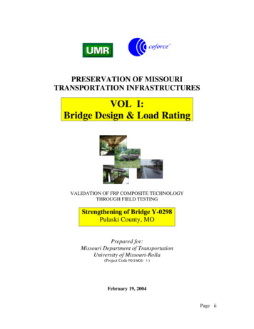
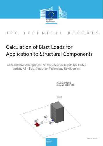
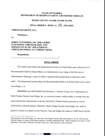
6.2 Permanent LoadsThe LRFD Specification refers to the weights of the following as “permanent loads”: The structureFormwork which becomes part of the structureUtility ducts or casings and contentsSignsConcrete barriersWearing surface and/or potential deck overlay(s)Other elements deemed permanent loads by the design engineer and ownerEarth pressure, earth surcharge, and downdragThe permanent load is distributed to the girders by assigning to each all loads from superstructureelements within half the distance to the adjacent girder. This includes the dead load of the girderitself and the soffit, in the case of box girder structures. The dead loads due to concrete barrier,sidewalks and curbs, and sound walls, however, may be equally distributed to all girders.6.3 Vehicular Live LoadsThe design vehicular live load was replaced in 1993 because of heavier truck configurations on theroad today, and because a statistically representative, notional load was needed to achieve a “consistent level of safety.” The notional load that was found to best represent “exclusion vehicles,” i.e.,trucks with loading configurations greater than allowed but routinely granted permits by agencybridge rating personnel, was adopted by AASHTO and named “Highway Load ’93” or HL93. Themean and standard deviation of truck traffic was determined and used in the calibration of the loadfactors for HL93. It is notional in that it does not represent any specific vehicle [2].The distribution of loads per the LRFD Specification is more complex than in the StandardSpecifications for Highway Bridge Design [3]. This change is warranted because of the complexityin bridges today, increased knowledge of load paths, and technology available to be more rationalin performing design calculations. The end result will be more appropriately designed structures.6.3.1 Design Vehicular Live LoadThe AASHTO “design vehicular live load,” HL93, is a combination of a “design truck” or “designtandem” and a “design lane.” The design truck is the former Highway Semitrailer 20-ton designtruck (HS20-44) adopted by AASHO (now AASHTO) in 1944 and used in the previous StandardSpecification. Similarly, the design lane is the HS20 lane loading from the AASHTO StandardSpecifications. A shorter, but heavier, design tandem is new to AASHTO and is combined with thedesign lane if a worse condition is created than with the design truck. Superstructures with very shortspans, especially those less than 12 m in length, are often controlled by the tandem combination.The AASHTO design truck is shown in Figure 6.1. The variable axle spacing between the 145 kNloads is adjusted to create a critical condition for the design of each location in the structure. Inthe transverse direction, the design truck is 3 m wide and may be placed anywhere in the standard3.6-m-wide lane. The wheel load, however, may not be positioned any closer than 0.6 m from thelane line, or 0.3 m from the face of curb, barrier, or railing.The AASHTO design tandem consists of two 110-kN axles spaced at 1.2 m on center. TheAASHTO design lane loading is equal to 9.3 N/mm and emulates a caravan of trucks. Similar tothe truck loading, the lane load is spread over a 3-m-wide area in the standard 3.6-m lane. The laneloading is not interrupted except when creating an extreme force effect such as in “patch” loadingof alternate spans. Only the axles contributing to the extreme being sought are loaded. 2000 by CRC Press LLC
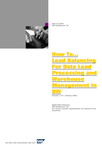
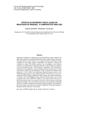
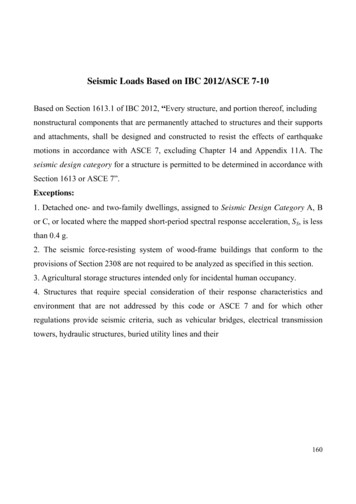
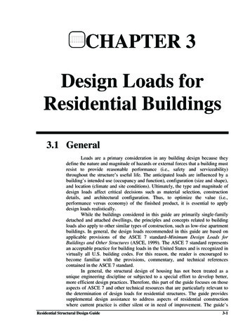
FIGURE 6.1 AASHTO-LRFD design truck. (AASHTO LRFD Bridge Design Specifications 2nd. ed., AmericanAssociation of State Highway and Transportation Officials. Washington, D.C., 1998. With permission.)When checking an extreme reaction at an interior pier or negative moment between points ofcontraflexure in the superstructure, two design trucks with a 4.3-m spacing between the 145-kNaxles are to be placed on the bridge with a minimum of 15 m between the rear axle of the first truckand the lead axle of the second truck. Only 90% of the truck and lane load is used. This procedurediffers from the Standard Specification which used shear and moment riders.6.3.2 Permit VehiclesMost U.S. states have developed their own “Permit Design Vehicle” to account for vehicles routinelygranted permission to travel a given route, despite force effects greater than those due the designtruck, i.e., the old HS20 loading. California uses anywhere from a 5- to 13-axle design vehicle asshown in Figure 6.2 [4]. Some states use an HS25 design truck, the configuration being identicalto the HS20 but axle loads 25% greater.The permit vehicular live load is combined with other loads in the Strength Limit State II asdiscussed in Chapter 5. Early editions of the AASHTO Specifications expect the design permit vehicleto be preceded and proceeded by a lane load. Furthermore, adjacent lanes may be loaded with thenew HL93 load, unless restricted by escort vehicles.6.3.3 Fatigue LoadsFor fatigue loading, the LRFD Specification uses the design truck alone with a constant axle spacingof 9 m. The load is placed to produce extreme force effects. In lieu of more exact information, thefrequency of the fatigue load for a single lane may be determined by multiplying the average dailytruck traffic by p, where p is 1.00 in the case of one lane available to trucks, 0.85 in the case of twolanes available to trucks, and 0.80 in the case of three or more lanes available to trucks. If the averagedaily truck traffic is not known, 20% of the average daily traffic may be used on rural interstatebridges, 15% for other rural and urban interstate bridges, and 10% for bridges in urban areas.6.3.4 Load Distribution for Superstructure DesignFigure 6.3 summarizes load distribution for design of longitudinal superstructure elements. Loaddistribution tables and the “lever rule” are approximate methods and intended for most designs. 2000 by CRC Press LLC
FIGURE 6.2 Caltrans permit truck. (AASHTO LRFD Bridge Design Specifications 2nd. ed., American Associationof State Highway and Transportation Officials. Washington, D.C., 1998. With permission.)The lever rule considers the slab between two girders to be simply supported. The reaction isdetermined by summing the reactions from the slabs on either side of the beam under consideration.“Refined analysis” refers to a three-dimensional consideration of the loads and is to be used onmore complex structures. In other words, classical force and displacement, finite difference, finiteelement, folded plate, finite strip, grillage analogy, series/harmonic, or yield line methods arerequired to obtain load effects for superstructure design.Note that, by definition of the vehicular design live load, no more than one truck can be in onelane simultaneously, except as previously described to generate maximum reactions or negativemoments. After forces have been determined from the longitudinal load distribution and thelongitudinal members have been designed, the designer may commence load distribution in thetransverse direction for deck and substructure design.6.3.4.1 DecksDecks may be designed for vehicular live loads using empirical methods or by distributing loadson to “effective strip widths” and analyzing the strips as continuous or simply supported beams. 2000 by CRC Press LLC
FIGURE 6.3Live-load distribution for superstructure design.Empirical methods rely on transfer of forces by arching of the concrete and shifting of the neutralaxis. Loading is discussed in Chapter 24, Bridge Decks and Approach Slabs.6.3.4.2 Beam–Slab BridgesApproximate methods for load distribution on beam–slab bridges are appropriate for the types ofcross sections shown in Table 4.6.2.2.1-1 of the AASHTO LRFD Specification. Load distribution 2000 by CRC Press LLC
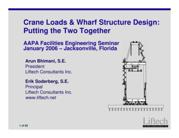
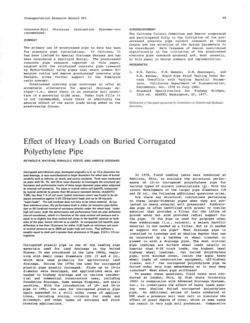
TABLE 6.1Reduction of Load Distribution Factors for Moment in Longitudinal Beams on Skewed SupportsType of SuperstructureConcrete deck, filled grid, orpartially filled grid on steel orconcrete beams, concreteT-beams, or double T-sectionsConcrete deck on concrete spreadbox beams, concrete box beams,and double T-sections used inmultibeam decksApplicableCross Section fromTable 4.6.2.2.1-1a, e, kAny Number ofDesign Lanes Loaded1 c1 (tan θ)1.5i, j, if sufficientlyconnected to act asa unitb, c, f, g0.250.25 K Sc1 0 .25 g3 Lts L if θ 30 , then c1 0if θ 60 , use θ 60 1.05 – 0.25 tan θ 1.0if θ 60 , use θ 60 Range ofApplicability30 θ 60 1100 S 49006000 L 73,000Nb 40 θ 60 Source: AASHTO LRFD Bridge Design Specifications, 2nd. ed., American Association of State Highway andTransportation Officials. Washington, D.C., 1998. With permission.factors, generated from expressions found in AASHTO LRFD Tables 4.6.2.2.2a–f and 4.6.2.2.3a–c,result in a decimal number of lanes and are used for girder design. Three-dimensional effects areaccounted for. These expressions are a function of beam area, beam width, beam depth, overhangwidth, polar moment of inertia, St. Venant’s torsional constant, stiffness, beam span, number ofbeams, number of cells, beam spacing, depth of deck, and deck width. Verification was done usingdetailed bridge deck analysis, simpler grillage analyses, and a data set of approximately 200 bridgesof varying type, geometry, and span length. Limitations on girder spacing, span length, and spandepth reflect the limitations of this data set.The load distribution factors for moment and shear at the obtuse corner are multiplied by skewfactors as shown in Tables 6.1 and 6.2, respectively.6.3.4.3 Slab-Type BridgesCast-in-place concrete slabs or voided slabs, stressed wood decks, and glued/spiked wood panelswith spreader beams are designed for an equivalent width of longitudinal strip per lane for bothshear and moment. That width, E (mm), is determined from the formula:E 250 0.42 L1W1(6.1)E 2100 0.12 L1W1 W N L(6.2)when one lane is loaded, andwhen more than one lane is loaded. L1 is the lesser of the actual span or 18,000 mm, W1 is the lesserof the edge-to-edge width of bridge and 18,000 mm in the case of single-lane loading, and18,000 mm in the case of multilane loading, and NL is the numbr of design lanes.6.3.5 Load Distribution for Substructure DesignBridge substructure includes bent caps, columns, pier walls, pile caps, spread footings, caissons,and piles. These components are designed by placing one or more design vehicular live loads onthe traveled way as previously described for maximum reaction and negative bending moment, notexceeding the maximum number of vehicular lanes permitted on the bridge. This maximum maybe determined by dividing the width of the traveled way by the standard lane width (3.6 m), and“rounding down,” i.e., disregarding any fractional lanes. Note that (1) the traveled way need not be 2000 by CRC Press LLC
TABLE 6.2Correction Factors for Load Distribution Factors for Support Shear of the Obtuse CornerApplicable CrossSection fromTable 4.6.2.2.1-1Type of SuperstructueCorrection Factor0 θ 60 1100 S 49006000 L 73,000Nb 4Concrete deck, filled grid, or partially filled gridon steel or concrete beams, concreteT-beams or double T-sectionsa, e, kMulticell concrete box beams, box sectionsdL 1.0 0.25 tan θ70 d 0 θ 60 1800 S 40006000 L 73000900 d 2700Nb 3Concrete deck on spread concrete box beamsb, c1.0 Ldtan θ6S0 θ 60 1800 S 35006000 L 43,000450 d 1700Nb 3Concrete box beams used in multibeam decksf, g1.0 i, j, if sufficientlyconnected to actas a unit—Range ofApplicability Lt 3 1.0 2.0 s Kg L tan θ90 d0.3tan θ0 θ 60 6000 L 37,000430 d 1500900 b 15005 Nb 20Source: AASHTO LRFD Bridge Design Specifications, 2nd. ed., American Association of State Highway andTransportation Officials. Washington, D.C., 1998. With permission.measured from the edge of deck if curbs
truck (HS20-44) adopted by AASHO (now AASHTO) in 1944 and used in the previous Standard Specification. Similarly, the design lane is the HS20 lane loading from the AASHTO Standard Specifications. A shorter, but heavier, design tandem is new to AASHTO and is combined with the design lane if a worse condition is created than with the design truck. Superstructures with very short