Transcription
Manual ultrasonic inspection of thin metal weldsCapucine Carpentier and John RudlinTWICambridge CB1 6AL, UKTelephone 01223 899000Fax 01223 890689E-mail capucine.carpentier@twi.co.ukAbstractBS EN ISO 17640 contains standard ultrasonic inspection techniques for ferritic steelwelds. The techniques in general include scans with different angles from either side ofthe weld.The minimum thickness noted in this standard is 8mm. However there are an increasingnumber of applications involving smaller thicknesses (e.g., containments) and thesecannot strictly be inspected by these methods.This paper describes a series of experiments of conventional ultrasonic and phased arraytesting on thin butt welded sections with simulated flaws using the procedures describedin BS EN ISO 17640 and BS EN 13588 but allowing the use of high frequency andsmall probes easily available in the market. The results show that the procedures of BSEN ISO 17640 can be adapted in this way for detection scanning and sizing forthicknesses down to 4mm.1.IntroductionThin walled vessels and pipes are increasingly required to be tested non-destructivelywhen they are used to contain substances that can damage a local environment.Examples include some designs of nuclear waste storage vessels, nuclear processingplant, low pressure oil pipes and other fuel systems. Different welding methods forstainless and duplex steel are also under investigation for these areas. Equally there is aneed to determine the actual size of a remaining ligament as this has a significant effecton fracture mechanics analyses.Conventional ultrasonic testing (according to BS EN ISO 17640) (1) limits thicknessesthat can be examined to less than 8mm. Similarly, the draft phased array standard BSEN 13588 (2) goes down to 6mm. Smaller thicknesses are frequently inspected byradiography, this cannot normally give the through thickness information required forfracture mechanics analyses. There is a requirement for non-destructive test methods inthe smaller thickness ranges. Bird (3) reported an experiment comparing manual UT andphased array with thicknesses down to 6mm with good results for good operators usingboth techniques. New or different technologies, such as eddy current arrays or highfrequency ultrasonic phased arrays may be needed for smaller thicknesses. A special
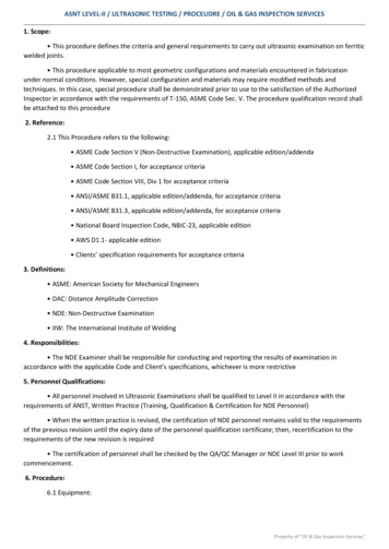
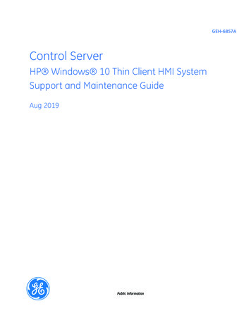
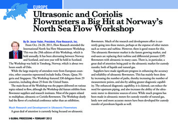
case where ultrasonic methods have been developed for a thin wall has been given byBird et al.(4) Some work on eddy currents is reported in this conference (5). However,from the manufacturers’ point of view it is convenient to refer to a standard whenrequesting items to be made, and to know what the actual limitations are of the currentUT methods.The main purpose of this paper is therefore to examine whether the normal manualultrasonics procedures used in the standard can be applied with minimum modificationto inspect arc welds in thin sections and whether phased array techniques can improveon this. The reason that the 8mm limit applies in most cases is that it is not possible withthinner sections to apply standard UT probes because they cannot approach the weldclose enough nor can the beam be easily defined. The modification to the standardprocedure adopted is to allow the use of high frequency 10MHz angled beam probes.Phased array technology for weld inspection is becoming mature, with a draft standardfor weld inspection BS EN 13588(6), and this standard and technique were also adopted.2.Test SamplesThe test samples specified consisted of plates 3, 4 and 5mm thick in ferritic andstainless steel, each containing 4 flaws. Figure 1 shows the position of these in the 4mmplate, the others were similar. The weld has a 60 preparation and there are threeembedded lack of fusion flaws at the weld cap and one root lack of fusion flaw in eachplate.The flaws have been made with intended dimensions and those supplied by themanufacturer, and these are used in the analysis. However, it should be noted thatmanufacture and measurement of such flaws has some uncertainties so the resultsobtained must be viewed with this in mind.A radiographic inspection of these welds was performed in order to verify the length ofthese flaws (Table1). As expected, the radiography was not able to reliably detect lackof side wall fusion.Carbon steelFlawsDetected?LengthStainless steelFlawsDetected?LengthTable 1. Results of radiographic inspection of welds3mm plate4mm plate5mm plateABCD ABCDABCNYNN NYNYNY Y\12\\\123\12 153mm plate4mm plate5mm plateABCD ABCDABCYYNN NYNNNY N712\\\12\\\12\DN\DY152
Length: 10mmLength: 10mmLength: 5mmLength: 15mmFigure 1 Position of the simulated flaws in the welds3.Manual UT3.1.Standard RequirementsThe international standard for the manual ultrasonic testing of fusion-welded joints inmetallic material BS EN 1714 has been withdrawn in 2010 and replaced by BS EN ISO17640:2010. This standard is specified to be applied for the testing of fusion weldedjoints in metallic material of thickness greater than or equal to 8mm and where both thewelded parent material are ferritic.The probe frequency specified in this standard are to be within the range 2 and 5MHz.However, the standard allows the use of higher frequency for improving rangeresolution if necessary for acceptance criteria based on characterisation of indications. Itis also required that at least one angle beam shall be normal or nearly normal to theweld fusion face.The testing volume is to include the weld body and at least 10mm on each side of theweld to cover the heat affected zone (HAZ).The standard is open to several techniques to set the sensitivity. One of the techniquesspecified in the standard allows the use of reference from a distance-amplitude curve(DAC) for side-drilled holes of diameter 3mm. Reference can also be made on notches3
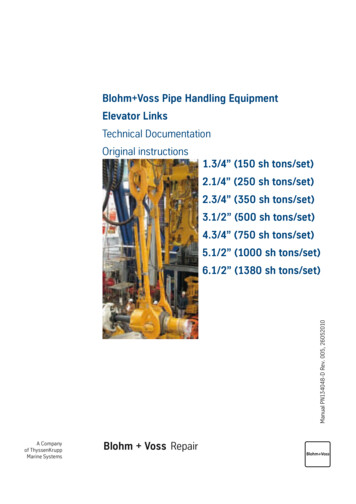
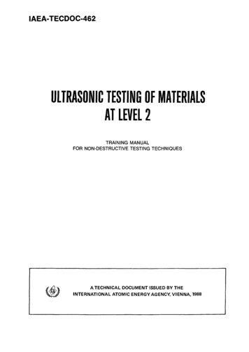
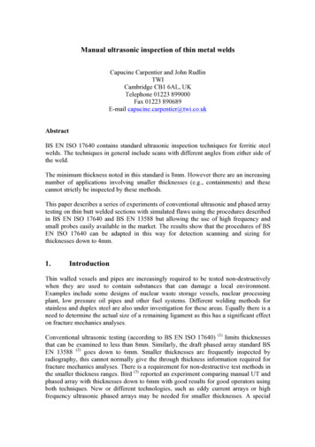
of 1mm wide with a depth of 1mm only for the thickness range between 8 and 15mmand for angle beam angles larger than 70 .BS EN 17640:2010 refers to BS IS 11666:2010 for the definition of the evaluation levelabove which an indication will be investigated. For an acceptance level 2, whichcorresponds to the most common quality level, the level of evaluation is set at -14dBbelow reference level.3.2.Equipment and ProcedureThe equipment used to carry out the manual testing was a Sonatest Masterscan 380Mwith 10MHz transducers 45, 60 and 70 , 6.35mm crystal diameter. The transducers usedfor the testing are shown in Figure 2. The footprints of these transducers were between20 to 30mm and enabled the probe index point to be close to the weld cap and hencereduce the number of ultrasonic skips on the back wall.As has been mentioned above the procedures of BS17604 together with an allowancefor the use of high frequency probes has been used. DAC was used relative to a 3mmSDHs.No attempt was made to have blind trials in this case. The operator had someknowledge of the flaw location and was seeking to identify and use the indication.a)b)c)Figure 2 Pictures of ultrasonic transducer Parametrics A544S 10 by 0.25a) 45 wedgeb) 60 wedgec) 70 wedge4.Phased Array UT4.1.Standard RequirementsThe use of (semi-)automated phased array technology for the inspection of welds iscovered by the draft international standard BS EN ISO 13588 which is currently open topublic comments. This standard specifies the application of the phased array technologyfor fusion welded joints in metallic materials equal to and above 6mm thickness.4
This standard is open to the use of linear scan (E-scan) and sector scan (S-scan) at afixed distance to the weld to generate multi angle beam from a single position of thetransducer. In addition, this standard specifies the use of scanning mechanism thatallows data collection with a scanning increment of no more than 1mm for componentthicknesses up to 10mm.It is also required to perform prior testing sensitivity setting for each beam and focalpoint generated by the phased array probe. The use of angle corrected gain (ACG) andtime corrected gain (TCG) shall be used to display the signals for all beam angles andall distances with the same amplitude. The standard provides recommendation on thetype, size and positions of reference reflector to be used for the sensitivity settings. Fora thickness between 6 and 25mm, a notch of 1mm deep or a 2.5mm diameter SDH canbe used.In addition, there is no specification in this standard regarding a set level for assessmentof indication. This is based in accordance with specified acceptance level andacceptance level applied.4.2.TechniquesThe samples were inspected with ultrasonic phased array using the off the shelvetransducer 10L16 SA00 N60S manufactured by Olympus as shown in Figure 3. Thistransducer generates shear waves at 10MHz using 16 elements. This transducer istraditionally used for aerospace applications and presents the advantages to have arelatively foot print (21mm) which allow to come close to the weld cap.The weld root and fusion face were inspected using a sector scan generating ultrasonicbeams from 45 to 75 with an angular resolution of 0.3 and three linear scans at 45, 60and 70 . The same delay laws were used for 5, 4 and 3mm thick plates. The ultrasonicbeams were focussed at different depths in order to take into account the multipleskipping on the back wall for different beam angles and plate thickness.The welds were examined from both sides and at two index offsets from the centre ofthe weld in order to cover the weld fusion face at different angle of incidence. The indexoffsets were different for each thickness. Figure 4 shows the ray tracing of the beamsgenerated by the sector and linear scans for a weld 5mm thick and at the two indexposition from the weld centre. The aim was to choose the right index offset in order toensure that the weld fusion face, cap and root were covered by at least two differentangles.As required in most codes and standards for phased array testing, the wedge attenuationand delay compensation was carried out using the 25mm radius of the V2 calibrationblock in both carbon and stainless steel. For each delay law, an ACG was set based on3mm SDH at a depth of 10mm in both carbon and stainless steel.A TCG was applied on each delay law in order to compensate the attenuation lossthroughout the range of the sound path. The TCG curves were generated using a seriesof 3mm diameter SDH at a depth of 5, 10 and 20mm. The plates were then scanned5
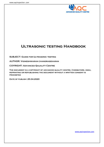
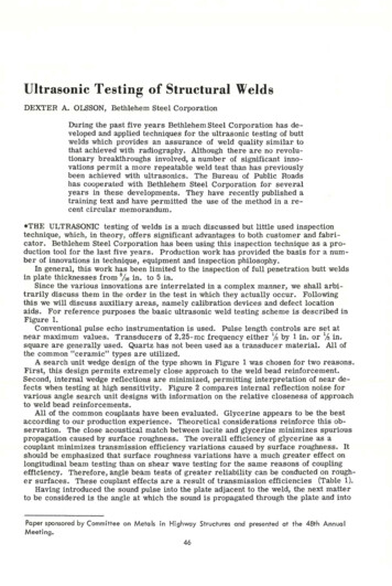
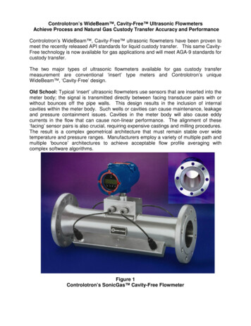
using a sensitivity set at TCG 6dB and TCG 12dB. The sensitivity level was alsochecked on notch with a depth equal to 10% of the thickness of the plate tested for thewelds in stainless steel. It was noted that the sensitivity on the notches was equivalent tothe sensitivity set on the SDHs within 10% FSH.Data were recorded using the Omniscan MX with a string encoder at a scanningresolution of 0.5mm.Figure 3 Picture of phased array transducer 10L16 SA00 N60S manufactured byOlympus and used in the study,a)b)Figure 4 Scan plan for the inspection of the 5mm thick plate (green lines 70 beam, red lines 60 , blue line 45 , pink line sector scan)a) Index offset at 7mmb) Index offset at 11mm6
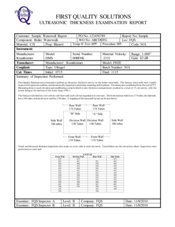
5.ModellingIn order to evaluate the length sizing resolution or lateral resolution of the inspectionand compare beam profile between the conventional and phased array testing, theultrasonic beams generated were modelled using the modelling platform CIVA v10.1.The ultrasonic beam size was extracted from the cross section of the ultrasonic beamsound pressure at a depth corresponding to the range where the weld is examined.Figure 5a shows the model configuration for a beam generated by the phased arraytransducer at 45 focussed at 7.5mm in depth and the ultrasonic beam modelled in 3D.The ultrasonic beam profile was also displayed along three cross section planes (X;Y),(Y;Z) and (X;Z) as shown in Figure 5b,5c and 5d. The maximum energy is displayed inblue. The projected 6dB beam width along the Y and X axis was exacted to evaluate thelateral resolution of the inspections and compare the performance of the techniques forthrough wall sizing.Table 2 summarises the beam width along the Y axis of the ultrasonic beams at 45, 60and 70 generated by the phased array techniques using sector and linear scans and bythe conventional method at the range for which the welds in the 3, 4 5mm plate areexamined. For the phased array techniques the beam size predicted was averaged for thestand-offs at 7 and 11mm.Along the 45 beam, and for the three thicknesses, the sector scan generates a smallerbeam of about 1mm smaller compared with the linear scan in the conventional method.Along the 60 beam, the sector and linear scans are equivalent but there is a slightincrease within 1mm of the beam width for the conventional method. Along the 70 beam, the phased array using the linear technique generates a smaller beam incomparison with the sectorial technique and the conventional method. In overall, thelinear techniques and conventional method provide a more regular beam width over thethree angle beams. The lateral resolution with a beam generated with the sectorialtechnique is better for the small angle beam but increase significantly at higher angle.Overall, the length sizing resolution generated with the methods used in this study isanticipated to be in average equal to 3mm.Table 2 Prediction of the 6dB ultrasonic beam width along the Y axis generated byphased array (PA) and conventional techniques at 45, 60 and 70 angle beams:Plate thickness Techniques45deg60deg70deg5mmPA Secto2.32.84.3PA Linear3.32.83.3Conv.3.43.73.84mmPA Secto2.12.14PA Linear3.22.82.1Conv.3.43.73.83mmPA Secto1.81.84PA Linear3.122.1Conv3.43.73.87
Table 3 summarises the beam width along the X axis of ultrasonic beams at 45, 60 and70 generated by the phased array techniques using sectorial scan and linear scan and bythe conventional method at the range for which the welds in the 3, 4 and 5mm plates areexamined. For the phased array techniques, the beam size predicted was averaged forthe stand-off at 7 and 11mm. Through wall sizing resolution is predicted by evaluatingthe beam dimension in the X/Z plane. The beam width given in Table 3 with modellingis the projected dimension of the beam width along the X axis. The projection of thebeam width along X axis was compared for all inspection techniques in order toevaluate the sizing capability.For the weld in the 5mm plate, the through wall resolution are equivalent for the threetechniques. As expected, the beam width increases with the angle of propagation.For the welds in the 4mm and 3mm plates, beam width for through wall resolution areequivalent along the 45 beam for the three techniques. Along the 60 beam, there is asignificant difference in the beam width between the sectorial scan and the linear scanwith the sectorial scan generating a smaller beam. The conventional testing providesequivalent performance as the linear scans. Along the 70 , there is a significant increasein the beam width for the three techniques. The largest increase and the largest beamwidth are generated by the sectorial scan.In conclusion, the sectorial scan provides a better beam characteristic at low anglecompare with the linear and conventional methods. However the performance with thesector scan decreased significantly and become less beneficial than the linear andconventional methods at high angle.Table 3 Prediction of the 6dB ultrasonic beam width along the X axis generated byphased array (PA) and conventional (Conv.) techniques at 45, 60 and 70 anglebeams:Plate thickness Technique45deg 60deg70deg5mmPA Secto2.73.97.8PA Linear3.23.85.8Conv.3.24.47.14mmPA Secto2.62.69.3PA Linear3.346.1Conv.3.24.47.13mmPA Secto2.62.69.3PA Linear3.44.26.1Conv3.24.47.18
a)b)c)d)Figure 5 Prediction of the ultrasonic beam profile generated at 45 with thephased array transducera) 3D modellingb) Beam cross section along (Y;Z) planec) Beam cross section along (X;Y) planed) Beam cross section along (X;Z) plane6.Results6.1.Manual UTTables 4 and 5 summarise the inspection results of the conventional ultrasonic testingon the weld sample for carbon steel and stainless steel respectively. Some of the flawswere not detected either because no signal has been discriminated from the noise orbecause the signal amplitude was below the -14dB evaluation level but identified fromthe noise. The latest case is identified in the tables when the amplitude is 14.Most of the flaws in the 5 and 4mm thick plates were detected. Not all the flaws in the3mm welds were detected. It can be noted that the level of detection of flaws in carbonsteel and stainless steel are equivalent. For these small thicknesses, the anisotropic andattenuative property of the stainless steel does not seem to have a particular effect on theperformance of the ultrasonic testing.It was not possible to measure the through wall size of the flaws. The operator was notable to identify the edge of the flaw either with the 6dB drop technique or max9
amplitude. The spatial and temporal resolution was not good enough for through wallsizing.Table 4 Inspection results for the conventional ultrasonic testing of welds incarbon steel:3mm plate4mm plate5mm plateFlawsABCD ABCDABCDetected?YYNN YYNYNY YBeam angle707070/ 45 4570604570 45dB from DAC -12 -14 14 / -4 -12 14 -8 14-5 -8Ligament///////////Through wall///////////Length45// 618/3/16 6DY45-7//16Table 5 Inspection result for the conventional ultrasonic testing of welds instainless steelFlawsDetected?Beam angledB from DACLigamentThrough wallLength6.2.AN/////3mm plateBCDYNY45/60-14/-7//////3/6AY60-2//114mm plateBCDYNY70/45-11/ 1.5//////5/55mm plateABCYYY7060 600.5-54//////1287DY704//7Phased ArrayTables 6 and 7 summarise the inspection results of the phased array testing on the weldsamples for respectively carbon steel and stainless steel.Figures 6 to 8 show some example of the plane view (C-scan) of the data collected withthe phased array from both side of the weld (skew 270 and 90 ). The blue axis providesthe position and length of the flaws. On the green axis the position of the flaws withregard to the weld centreline (at zero) is shown.The phased array inspection provided a good detection for the welds 5 and 4 mm thick.From the plane view, in the 5mm thick weld in carbon steel and in the 4mm thick weldin stainless steel, the four flaws were clearly identified from the data. The data on thestainless steel was fairly clear and did not show a strong signal from the root as shownin Figure 7.In the 3mm thick weld in carbon steel and stainless steel (Figure 8), strong indicationsare noted along the weld coming from multi-reflection from the cap and the root whichmask the reflection from the flaws. In addition, signals from the flaws in the welds 3mmthick are not expected to be high amplitude. Gain was then increased which made the10
inspection on the stainless steel worst as the noise level from the weld were higher thanthe flaws signals.Figure 9 shows the data from the flaw B in the 5mm thick weld in stainless steel. Theflaw B is intended to be vertical lying at the weld root. The data shows effectively anindication from the corner and the tip of the flaws from which the flaw through wallheight was measured.Flaw C shown in Figure 10 for the 5mm thick weld in stainless steel is lying along theweld fusion face, specular to the ultrasonic beam. Assuming that the flaw was biggerthan the beam width, the through wall sizing was possible using 6dB drop on either sideof the flaw edge.Table 6 Inspection result for the phased array testing of welds in carbon steel3mm plate4mm plate5mm plateFlawsAB C D ABCDABCDDetectedYN N N YNYYYYYY?Techniqu SectoSectSect Linea Linea Linea Linea Linea/ / //erororrrrrrBeam48/ / /48/606045704545angle84%Amplitud 100 10030% / / / 80% / (3dB 52%76%75%e%%)Ligament0/ / / -0.6/-2.5-2.2-0.3-3.3-1.8-1Through0.6/ / / 1.6/2.02.01.21.70.32.8wallLength9/ / / 11.5 /5611.513.5615Table 7 Inspection result for the phased array testing of welds in stainless steel:3mm plate4mm plate5mm plateFlawsA B C DABCDABCDetected N N N YYYYYYYY?Techniqu / / / Secto Secto Secto Secto Secto Secto Secto SectoerrrrrrrrBeam/ / /6551765070495352angleAmplitud / / / 100 55%70% 100% 55%80%41% 100e%(3dB) (3dB)%Ligament / / / 1.4-1-2.9-1.7-1.1-0.3-3.2-1.5Through / / / 1.41.61.11.72.81.70.82.8wallLength / / /1948.58.58111010DYSector52 100%-3.13.01711
a)b)Figure 6 Plane view of the data collected with phased array on the 5mm platein carbon steel at sensitivity TCG 12dB froma) sector scan at 11mm stand off at skew 270 b) sector scan at 7mm stand off at skew 90 a)12
b)Figure 7 Plane view of the data collected with phased array on the 4mm platein stainless steel at sensitivity froma) sector scan at 7mm stand off, TCG 3dB, at skew 270 b) sector scan at 7mm stand off, TCG 6dB, at skew 90 a)b)Figure 8 Plane view of the data collected with phased array on the 3mm platein carbon steel at sensitivity froma) sector scan at 11mm stand off, TCG 12dB, at skew 270 b) sector scan at 11mm stand off, TCG 12dB, at skew 90 13
a)b)Figure 9 Flaw B phased array data on sample 5mm in stainless steela) sector scan, stand-off 7mm, 6dB, skew 90 b) detail of Flaw B, sector scan, stand-off 7mm, 6dB, skew 90 14
Figure 10 Flaw C phased array data on sample 5mm in stainless steel , sectorscan, stand-off 11mm, 3dB, skew 90 7.DiscussionIt can be noted that the level of detection between the conventional method and phasedarray techniques is similar for the plate 4 and 5mm. For the 3mm plate, the conventionalmethod gives detection of more flaws. This could be because in conventional testing theoperator can skew the probe and hence discriminate the signal from a flaw to othergeometry features such the root and geometry which are very close together in time forweld in small thickness.Phased array testing provides, by displaying the data in plane and cross section views,the advantage to ease the interpretation of the signals and hence allows in some casesthrough wall sizing using tip diffraction for vertical flaw and specular reflection for flawsuch as LOF. In addition, length sizing seems to be closer with phased array to theintended flaw size and also the result from the radiography.8.1.ConclusionsBS EN standards for the use of conventional ultrasonic and phased array testing forwelds is today limited for the examination of thickness larger than 8mm for theconventional method and 6mm for the phased array. From this study, it has beenshown that this standard could be extended to weld larger than 4mm thick in thecondition that a small foot print and high frequency transducer is used (higher than10MHz) and the sensitivity settings is set on reference target representative to thesize of flaws to be found in small thickness ie use of small diameter SDHs ornotches.15
2.The phased array method has the advantage of a display which gives easierinterpretation of signals and hence better sizing and characterisation of flaws.However, at the smallest thickness, it has been shown that allowing the probe to bemoved freely in all direction along the weld as used with the conventional testinghelped detection of flaws in comparison with the rigid scan from a fixed distancefrom the weld used with phased array. Therefore, for this thickness below 4mm, afree manual scan using phased array techniques could be recommended for thedetection of flaws. This could then be followed by encoded scans in the areapresented indications to be investigated.AcknowledgementsThe work was funded by TWI’s Core Research Programme. Full reports are available tomember companies of TWI.References1.BS EN ISO 17640:2010, “Non-destructive testing of welds – Ultrasonic testing– Techniques, testing levels, and assessment.”2. & 6. Draft BS EN ISO 13588, “Non-destructive testing of welds – Ultrasonic testing– Use of (semi) automated phased array technology.”3.Schneider C R A and Bird C R, “Reliability of manually applied phased arrayinspection”, 4th European-American Workshop on Reliability of NDE, Berlin,June 2009, rd C R and Pettigrew I, “Qualification of a phased array inspection of thinweld.” 18th World Conference on Non-destructive Testing, Durban, April 2012.5.Majidnia S and Rudlin J, “Depth of Penetration Effects in Eddy CurrentTesting”, 51st Annual Conference of The British Institute of Non-DestructiveTesting, Daventry, September 2012.16
The international standard for the manual ultrasonic testing of fusion-welded joints in metallic material BS EN 1714 has been withdrawn in 2010 and replaced by BS EN ISO 17640:2010. This standard is specified to be applied for the testing of fusion welded joints in metallic material of