Transcription
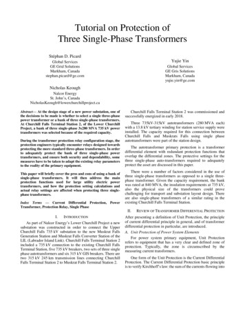
Tutorial on Protection ofThree Single-Phase TransformersStéphan D. PicardYujie YinGlobal ServicesGE Grid SolutionsMarkham, Canadastephan.picard@ge.comGlobal ServicesGE Gris SolutionsMarkham, Canadayujie.yin@ge.comNicholas KeoughNalcor EnergySt. John’s, act— At the design stage of a new power substation, one ofthe decisions to be made is whether to select a single three-phasepower transformer or a bank of three single-phase transformers.At Churchill Falls Terminal Station 2, of the Lower ChurchillProject, a bank of three single-phase 3x280 MVA 735 kV powertransformers was selected because of the required capacity.During the transformer protection relay configuration stage, theprotection engineers typically encounter relays designed towardsprotecting the more standard three-phase transformers. In orderto adequately protect the bank of three single-phase powertransformers, and ensure both security and dependability, somemeasures have to be taken to adapt the existing relay parametersto the reality of the primary equipment.This paper will briefly cover the pros and cons of using a bank ofsingle-phase transformers. It will then address the mainprotection functions used for large utility electric powertransformers, and how the protection setting calculations andactual relay settings are affected when protecting three singlephase transformers.Index Terms — Current Differential Protection, PowerTransformer, Protection Relay, Single PhaseChurchill Falls Terminal Station 2 was commissioned andsuccessfully energized in early 2018.Three 735kV-315kV autotransformers (280 MVA each)with a 13.8 kV tertiary winding for station service supply wereinstalled. The capacity required for this connection betweenChurchill Falls and Muskrats Falls using single phaseautotransformers were part of the station design.The autotransformer primary protection is a transformerdifferential element with redundant protection functions thatoverlap the differential zones. The protective settings for thethree single-phase auto-transformers required to adequatelyprotect the asset are discussed in this paper.There were a number of factors considered in the use ofthree single-phase transformers as opposed to a single threephase transformer. Given the capacity requirement, the bankwas rated at 840 MVA, the insulation requirements at 735 kV,also the physical size of the transformers could provechallenging for transport and substation layout design. Thereare also single-phase transformers of a similar rating in theexisting Churchill Falls Terminal Station.II.I.INTRODUCTIONAs part of Nalcor Energy’s Lower Churchill Project a newsubstation was constructed in order to connect the UpperChurchill Falls 735 kV substation to the new Muskrat FallsGeneration Station and Muskrat Falls Converter Station of theLIL (Labrador Island Link). Churchill Falls Terminal Station 2included a 735 kV connection to the existing Churchill FallsTerminal Station, five 735 kV breakers, two sets of three singlephase autotransformers and six 315 kV GIS breakers. There aretwo 315 kV 245 km transmission lines connecting ChurchillFalls Terminal Station 2 to Muskrat Falls Terminal Station 2.REVIEW OF TRANSFORMER DIFFERENTIAL PROTECTIONAfter presenting a definition of Unit Protection, the principleof current differential principle in general, and of transformerdifferential protection in particular, are introduced.A. Unit Protection of Power System ElementsFor power system primary equipment, Unit Protectionrefers to equipment that has a very clear and defined zone ofprotection. Typically, the zone is circumscribed by themeasuring current transformers.One form of the Unit Protection is the Current DifferentialProtection. The Current Differential Protection basic principleis to verify Kirchhoff’s law: the sum of the currents flowing into
a node must equal the sum of the currents flowing out of thatnode. Whether the equipment is a busbar, a transmission line ora feeder; the sum of entering and leaving current must alwaysbe validated. When this is not true, typically a deviation ofcurrent to ground or to other parts of the power system isoccurring in manners that are abnormal, and this situation mustbe stopped.For most power system equipment, a simple phasorsummation of the currents can be performed and the result mustideally be zero – practically it is not exactly zero due tomeasurement errors. The power transformer is a special case.Its primary function is to operate at different voltage levelswhich means that the current is proportionally different. Thus,strictly applying a phasor summation to the transformercurrents would translate to non-zero results, incorrectlyindicating a current deviation. Some measures need to be takenand they will be explained in the next Section.Another phenomenon specific to power transformers is theireffect on voltage and current phase results from theirconstruction. In some instances, the outgoing transformercurrent is phase shifted with respect to the incoming current,resulting in an additional “error” when performing a simplephasor summation.B. Power Transformer Differential Protection1) Basics of Current Differential ProtectionThe relay performing Current Differential Protection on apower transformer must perform magnitude and phasecompensation in order to provide adequate safety and security.In order to ease the process for the end users, modern electronicrelays integrate widely accepted and simple method consistingin entering the power transformer parameters (MVA, windingconnections, winding voltages) as well as the currenttransformer ratios. With this information, the relay canautomatically determine a reference winding and calculate themagnitude and phase compensation factors in addition to thezero-sequence compensation (when applicable). Shall the userencounter a non-typical scenario, all of these compensationscan be entered manually by the protection engineer.To reduce the complexity of the compensations performed,a simple case is presented below. Considering a powertransformer of 100 MVA, 115 kV - 34.5 kV connected in YY0,the relay would perform the following steps. (To ease theunderstanding of the magnitude compensation, this exampleconsiders identical high-side and low-side CTs with a ratio of1800:5). An actual real scenario is presented later on inSection III.Step 1 – Calculate the rated current of each winding �� 3 𝑉𝑛𝑜𝑚which is:𝐼𝑟𝑎𝑡𝑒𝑑𝐻𝑖𝑔ℎ 𝐼𝑟𝑎𝑡𝑒𝑑𝐿𝑜𝑤100 𝑀𝑉𝐴 502.0 𝐴 3 115 𝑘𝑉100 𝑀𝑉𝐴 1673.4 𝐴 3 34.5 𝑘𝑉Step 2 – Select the reference winding, based on the CTmargin, as the winding that has the CT that is most likely tosaturate. The margin for each winding is calculated as:𝐼𝑚𝑎𝑟𝑔𝑖𝑛 CT Primary CurrentNominal Current1800 3.585021800 � 𝐼𝑚𝑎𝑟𝑔𝑖𝑛𝐿𝑜𝑤The winding with the lowest CT margin is selected as thereference winding.Step 3 – Calculate a magnitude compensation factor as:𝑘𝑤𝑖𝑛𝑑𝑖𝑛𝑔 𝐼𝑤𝑖𝑛𝑑𝑖𝑛𝑔 ��𝑒𝑓𝑒𝑟𝑒𝑛𝑐𝑒 ��which, for each winding, is𝑘𝐻𝑖𝑔ℎ 1800 115 3.331800 34.51800 34.5 1.01800 34.5Given the construction of the YY0 transformer in thisexample, phase compensation is not necessary. Similarly, zerosequence compensation is not required.𝑘𝐿𝑜𝑤 Step 4 – The differential protection operates with themagnitude-, phase- and zero sequence-compensated signals. Inthe simplified example above, the compensated currents arecalculated as:𝐼𝐴𝑐𝐼𝐵𝑐𝐼𝐶𝑐 𝑘𝑤𝑖𝑛𝑑𝑖𝑛𝑔 𝐼𝐴 𝑘𝑤𝑖𝑛𝑑𝑖𝑛𝑔 𝐼𝐵 𝑘𝑤𝑖𝑛𝑑𝑖𝑛𝑔 𝐼𝑐In the example above, the compensated high-side nominalcurrents would be (for phase A only at nominal load)𝐼𝐴𝑐ℎ𝑖𝑔ℎ 3.33 502 1671.6While the low-side would be𝐼𝐴𝑐𝑙𝑜𝑤 1.0 1673.4 1673.4It becomes clear that the compensated currents can now becompared, or vectorially summed, as for a more standarddifferential protection.Using the compensated currents, the protection relay cancalculate the differential and restraint currents. While there arevariations among relay manufacturers, the basic principle is thesame. A differential current provides an indication of how manyamperes are not flowing through the primary or secondarywinding of the transformer and is obtained by a vector sum ofall currents, on a phase-by phase basis.
The restraint current provides an estimation of themagnitude of the currents flowing through or in the transformerand is used to adjust the relay sensitivity through the use of apercent differential characteristic, as shown in the Fig. 1 below.As can be seen, the beginning of the percent differentialcharacteristic is flat, to account for measurement error (andpossibly tap changer) when the transformer is lightly loaded.C. Considerations when Configuring a Transformer Relayfor Three Single-Phase TransformersMost commercially available current differential relays forpower transformer protection were designed to protect threewinding transformers. The relay transformer parameters aredesigned as such and, as seen above, are used to compute thecompensation factors.It is important to fully understand the specific model of agiven relay manufacturer. This is also true when it comes toconfiguring the transformer differential relay. For instance,manufacturer M1 uses the nominal power of the transformersimply to determine the winding that will be used as a reference.The current compensation factor is then calculated based on theCT ratios and nominal voltages. On the other hand,manufacturer M2 makes direct use of the nominal power tocalculate the compensation factor. The methodology used hasto be considered when configuring the relay.Continuing with the case of the simple YY0 transformerpresented above, the compensation factor was alreadycalculated for a relay from manufacturer M1.Fig. 1. Transformer Percent Differential CharacteristicObserving how a relay from manufacturer M2 operates, thecompensation is calculated as:It should be noted that each relay manufacturer introduces itsown peculiarity and, as such, it is crucial to have a thoroughunderstanding for a given relay model of a given manufacturer.The relay instruction manual is the first reference that should bereviewed (some examples can be found at [2]-[4]).2) A Note on Phase and Zero-Sequence Compensation,and Harmonic Restraint.The simplified example above demonstrated the basicprinciple of transformer current differential protection. Inaddition to the magnitude compensation shown above, there aretransformer configurations where phase compensation and/orzero-sequence compensation are required.If the windings do not align in terms of phase, and only themagnitude compensation is performed, then a false differentialcurrent will appear, even during normal conditions. This is theresult of the sum done with vectors that have a phase separation.This phase separation needs to be compensated for.Additionally, if a winding does not allow the circulation ofzero-sequence current (e.g., a delta-connected winding), then aground fault would allow the zero-sequence current to appearon one side of the transformer but not on the other side. Thiswould also present a false differential current to the relay, evenin the case of external faults. As such, the zero-sequence currentmust also be compensated for.Further explanation on these two compensations are outsidethe scope of this article and the reader is referred to otherreferences for more details [1].Also outside of the scope of this document is the harmonicrestraint. It is possible to detect transformer energization bymeasuring the 2nd harmonic of current, as well as overexcitationby measuring the 5th harmonic.𝑘𝑤𝑖𝑛𝑑𝑖𝑛𝑔 1000 𝑆𝑟𝑎𝑡𝑒𝑑 3 𝑉𝑛𝑜𝑚 𝐶𝑇𝑅whereSrated Transformer maximum MVA (MVA)Vnom Terminal line-to-line voltage of the winding (kV)When calculating the compensation factor, the followingresults are obtained.Table 1 Compensation FactorsWindingRelay M11-ph or 3-phHighLow3.331.0Relay M2Relay M31-ph 3-ph 1-ph 3-ph0.81 1.39 6.21 3.592.68 4.64 1.86 1.08For comparison purpose, the Table above also displays theresults for a relay from manufacturer M3, although the paperwill not go into the calculation details.This difference is important between 1-phase form and 3phase form when it comes to the setting calculation since it iseffectively expanding the axis of the differential characteristicgraph.As can be seen from these two sample relays, one relaywould be affected by whether the transformer parameters areentered as a three-phase transformer or as three single-phasetransformers, while the other relay would not be affected. Bothrelays will protect the asset adequately as long as the protectionengineer is aware of the differences and account for them.
III.SOLUTION PROPOSALTertiary CT Ratio (CTRTV)In the solutions proposed below, the simple transformerexample from above is left aside in order to present the real caseof the Churchill Falls Terminal Station 2 auto-transformers.A. Transformer Protection – Three-line AC DiagramFigure 2 shows the three-single phase transformers that areto be protected with transformer differential relays at ChurchillFalls Terminal Station 2.735 kVA B CNeutral CT Ratio (CTRN)Neutral CT Ratio (CTRN-GR)HV Rated Current (IRHV)LV Rated Current (IRLV)Tertiary Rated Current (IRTV)2000-1000:5(Interposing CT5:1 for 87TA relayonly)2000-1000:1 A600:5 A660 A1540 A725 AC. Two Possible SolutionsBelow are presented two methods to treat the transformer. Foreach method, the relay setting calculation are detailed.87TABC13.8 kVSingle PhaseAutotransformerT1, 3x280MVAABC1) Solution 1 – Treat as a Three-Phase TransformerSince the auto-transformer is connected with YNa0-D11,but the tertiary CTs are inside the Delta connection, set the CTconnection compensation to be 0/0/0 or 12/12/12 for terminalCT1, 2 and 3 respectively.315 kVFig. 2. Transformer Three-line Diagram for Differential ProtectionPlease note the tertiary CTs are inside the Delta. If thetertiary CTs are outside the tertiary, then the transformer can beprotected in the same manner as more standard three-phases,three-winding transformer. There will be magnitude and anglecompensation by the 87T, with straight-forward settings.However, the solution below is to address the tertiary CTs thatare located inside the Delta. Some relay settings need to betricked to ensure the 87T will provide adequate protection forthe transformer.B. Transformer ParametersTable 2 below lists the transformer parameters that are usedto calculate the transformer differential settings. Thetransformers are protected with redundant differential relaysfrom different manufacturers. To simplify the discussion, onlythe setting calculation for manufacturer M3 is discussed.Table 2 Single-Phase Power Transformer ParametersTransformer Rated MVA at ONAF2840 MVA(3x 280 MVA)HV Rated Voltage (VHV)LV Rated Voltage (VLV)Tertiary Rated Voltage(TLV)Transformer Winding ConnectionHV CT Ratio (CTRHV)LV CT Ratio (CTRLV)735 kV315 kV13.8 kVYNa0-D112000-1000:1 A4000-2000:1 A(87TA CT uses2000:1 TAP)Calculate the Magnitude Compensation ValuesThe protection relay from manufacturer M3 will calculatethe magnitude compensation factor (Kwinding) valuesautomatically using the MVA, winding voltage and CT ratio perthe following formula when the CT connection is wye. Pleasenote the Kwinging has to be calculated based on the three-phasetransformer parameters. (ST REF 840MVA; VHV 735kV,VLV 315kV, VTV 3*13.8 23.9kV). In the specific case of theNalcor single-phase autotransformers, the tertiary CT is locatedinside the Delta winding connection. Thus, there is no anglecompensation required and the tertiary voltage has to be set likea wye-connected transformer, which means the L-L voltage forthe relay setting will be 23.9kV.The HV CT ratio is selected as 2000:1, LV CT ratio set to4000:1, tertiary CT ratio set to 2000:5 and then the calculatedKwinding values as below:𝐾𝑤𝑖𝑛𝑑𝑖𝑛𝑔 𝑛𝐼𝑛𝑜𝑟𝑚 𝑐𝑡𝑝 𝑆𝑇 𝑅𝐸𝐹 1000 3 𝑉𝑚𝐾𝐻𝑉 3.031𝐾𝐿𝑉 2.597𝐾𝑇𝑉 0.0990.05 𝐾𝑤𝑖𝑛𝑑𝑖𝑛𝑔 15The KTV is very close to 0.05, but still in the settable range.Changing the CT ratio may not be necessary.Calculate the Differential Pickup ValueSince there is no tap-changer, tap error is not considered.Therefore, set the 87 pickup higher than the maximum errorcaused by the steady-state CT error and transformer excitationcurrent. Therefore, set the 87 pickup to 0.15 pu.Calculate the Slope Values (K1 and K2)
Set the K1 30% for maximum error caused by CT and relaymeasuring errors during a through fault condition and K2 80%for possible CT saturation for a higher current through fault.Calculate the Hi Set Instantaneous Differential ValueThe unrestrained differential element must be set to higherthan the large inrush current peak value (1750 A as obtainedfrom the transformer manufacturer), which is 2.7 times thetransformer HV rated current. Set to 6 pu.Therefore, set:87 pickup to 0.15 pu87 Slope 1 to 30%Is2 1.0 pu87 Slope 2 to 80 %87 Hi Set pickup 6 pu2) Solution 2 – Treat as Single-Phase Transformersprotection elements contained in the same multi-function relay,should be used to complement the differential, such as theoverexcitation (or V/Hz) and restricted earth fault protections.A. OverexcitationBecause transformers are typically operated near theinflexion of the iron saturation curve, relatively small increasesin voltages can result in large exciting currents in thetransformer which can lead to damage to the asset. Given thatthe voltage divided by the frequency is proportional to the fluxin the transformer, the ideal protection element against suchdamage is the volts per hertz function.Considering the IEEE Std C57.12.00 [5] which allows thetransformer to be operated up to 10% above the rated secondaryvoltage, this becomes a good criterion to set the overexcitationprotection element [6].Figure 3 below shows the overflux limit curve for thetransformer as well as the Overexcitation protection elementcurve protecting adequately the transformer.Calculate the Magnitude Compensation ValuesTo protect single-phase transformers, the parameters haveto be entered differently. The relay from manufacturer M3 cancalculate the Kwinging values automatically using the MVA,winding voltage and CT ratio per the following formula whenthe CT connection is wye. Please note the Kwinging has to becalculated based on the single-phase transformer parameters(STREF 280 MVA;VHV 424.4 kV,VLV 181.9 kV,VTV 13.8 kV) due to the tertiary CT being located inside thetransformer delta connection. The protection relay is designedfor a three-phase transformer. Therefore, when calculating theKwinding, 3 is included in the formula below.𝐾𝑤𝑖𝑛𝑑𝑖𝑛𝑔 𝑛𝐼𝑛𝑜𝑟𝑚 𝑐𝑡𝑝 𝑆𝑇 𝑅𝐸𝐹 1000Fig. 3. Transformer V/Hz Protection Curve 3 𝑉𝑚𝐾𝐻𝑉 5.242𝐾𝐿𝑉 4.5𝐾𝑇𝑉 0.1710.05 𝐾𝑤𝑖𝑛𝑑𝑖𝑛𝑔 15The KTV is very close to 0.05, but still in the settable range.Changing the CT ratio may not be necessary. The remainingparameters can be set the same as in Solution 1.As seen from the calculations in Solutions 1 and 2, when theCT is located inside of delta of the tertiary winding, the nominalvoltage used to calculate the Kwinding must be input into the relay 3 times the voltage (as if treated like a three-phasetransformer, which is 23.9kV and 13.8 kV respectively.) It canbe selected depending on the protection engineer’s preference.IV.OTHER PROTECTION FUNCTIONSIn the previous sections, the focus was mainly on thetransformer current differential function, which is the functionthat presents the biggest challenges for adequately protectingthe three single-phase transformers. Additionally, otherB. Restricted Earth FaultA ground fault occurring near the neutral point of a wyeconnected winding can result in fault current below the pickuplevel of overcurrent or differential elements. Such a fault candegenerate and lead to more serious ground faults or phase-tophase faults if not detected and cleared on time.The restricted earth fault element can mitigate this lowsensitivity by comparing the winding phase current with thecurrent circulating through the winding grounding impedance.While the current differential element provides protectiontypically for the top 70% of the winding, the restricted earthfault can cover the bottom 35% of that winding.The operating signal is typically of the form𝐼𝑜𝑝 𝐼𝐺 𝐼𝑁 𝐼𝐺 (𝐼𝐴 𝐼𝐵 𝐼𝐶 ) and to ensure the safety of the operation in front of CTsaturation conditions, this operating signal is compared to arestraint signal defined in order to prevent misoperations duringexternal ground or external phase-to-phase faults. An exampleof restraint signal from manufacturer M1 is
𝐼𝑟𝑒𝑠𝑡 𝑚𝑎𝑥{𝐼𝑅0 , 𝐼𝑅1 , 𝐼𝑅2 }where𝐼𝑅0 𝐼𝐺 𝐼𝑁 𝐼𝐺 (𝐼𝐴 𝐼𝐵 𝐼𝐶 ) and IR1, IR2 are respectively the positive- and negative-sequencecurrents.The operation of the protection element occurs when theoperating current is larger than the restraint current multipliedby a slope factor.V.CONCLUSIONWhen the specific application encountered by the protectionengineer does not match exactly the typical scenario envisionedand documented by the relay manufacturer, a thoroughunderstanding of basic principles and specifics of theequipment is required. In protecting three single-phasetransformers, settings for the transformer current differentialhave to be entered carefully to adapt to protection relaysdesigned to protect three-phase transformers. It can beaccomplished in more than one ways, but it first must be wellunderstood.Multi-function protection relays are able to protect thetransformer from conditions not easily detected by a currentonly protection element. For instance, from overvoltage thatcould cause heating and insulation damage, which can bedetected with an overexcitation function. Also from lowmagnitude ground fault current that could easily trip thetransformer in case of a ground fault near its neutral point.REFERENCESBooks:[1][2][3][4]J.L. Blackburn, T.J. Domin, Protective Relaying Principles andApplication Third Edition, Boca Raton, CRC Press, 2007.GE Grid Solutions, T60 Transformer Protection System InstructionManual for version 7.6x, 2017.Alstom, MiCOM P40 Agile P64x – Technical Manual – TransformerProtection IED, 2015.Schweitzer Engineering Laboratories, SEL-487E-3, -4 Relay – CurrentDifferential and Voltage Protection – Instruction Manual, Nov. 2016.Standards:[5][6]IEEE Standard for General Requirements for Liquid-ImmersedDistribution, Power, and Regulating Transformers, IEEE Std.C57.12.00-2010, Sep. 2010.IEEE Recommended practice for Protection and Coordination ofIndustrial and Commercial Power Systems, IEEE Std. 242-2001, June2001.[7]IEEE Guide for Protective Relay Applications to Power Transformers,IEEE C37.91-2000, Oct. 2000.Stéphan D. Picard (M’02) was born in Québec, Canada. Hereceived the B.Ing. degree in electrical engineering from theUniversity of Sherbrooke, Canada in 1997 and the technicalM.Eng. degree in electrical engineering from CarletonUniversity, Canada in 2001.Since 2002, he has been with General Electric Grid Solutions(Multilin) and is currently based in Montréal, Qc, Canada. Hiscurrent position is Senior P&C Application Engineer focusingon Phasor Measurement Unit, Power System Studies andRemedial Action Systems. Stéphan D. Picard is a registeredProfessional Engineer in the Province of Québec, Canada.Yujie Yin is a Senior Application Engineer in GE DigitalEnergy’s Technical Expertise team, where he is working onmany projects from North America utilities. He has over 20years of electric utility experience from initial studies todetailed substation design, construction and commissioning. Inthe last five years, he was especially focused on multi-vendorIEC61850 system integration activities, Remedial ActionSchemes (RAS) and Wide Area Measurement Protection andControl (WAMPC).He is a senior member of IEEE, CIGRE B5 WG and a licensedProfessional Engineer in the Province of Ontario and Alberta.He received his Bachelor of Computer Science and Master ofElectrical Engineering from Western University, Canada, andalso holds a Bachelor of Electrical Engineering degree fromHFUT, China.Nicholas Keough is from Botwood, Newfoundland andLabrador. He received his B.Eng. degree from MemorialUniversity of Newfoundland.Since 2013 Nicholas has been a Protection and ControlEngineer for Nalcor Energy working on the Lower ChurchillProject. His work has included design, installation andcommissioning of protection and control equipment for threeAC substations and HVDC link. Prior to working on LCP,Nicholas worked with Nalcor’s utility – Newfoundland andLabrador Hydro at the Holyrood Generating Station as PlantElectrical Engineer as well as with Maritime Electric inCharlottetown, PE as Electrical Engineer.Nicholas is a registered Professional Engineer in the Provinceof Newfoundland and Labrador.
three single-phase auto-transformers required to adequately protect the asset are discussed in this paper. There were a number of factors considered in the use of three single-phase transformers as opposed to a single three-phase transformer. Given the capacity requirement, the bank was