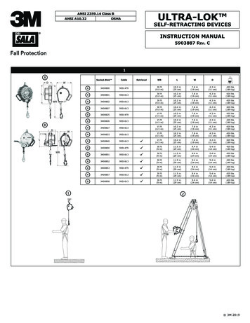
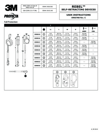
Transcription
Voltage RelayProduct Guide -ANSI versionREU 610
Voltage RelayREU 6101MRS 756026Issued: 01.02.2006Status: NewVersion: AData subject to change without noticeFeatures Overvoltage protection with definite-time orIDMT characteristic, low-set element Overvoltage protection with definite-time orIDMT characteristic, high-set element- Based on phase-to-phase voltage measurement or negative phasesequence(NPS) voltage Non-volatile memory for:- Up to 100 event codes with time stamp- Setting values- Disturbance recorder data- Recorded data of the five last eventswith time stamp Undervoltage protection with definite-timeor IDMT characteristic, lowset element- Number of pickups for protection elements- Can also be used as alarm element- Operation target messages and LEDsshowing the status at the moment ofpower failure Undervoltage protection with definite-timeor IDMT characteristic, highset element- Based on phase-to-phase voltage measurement or positive phasesequence(PPS) voltage Residual overvoltage protection with definite-time characteristic, low-set element Residual overvoltage protection with definite-time characteristic, high-set element HMI with an alphanumeric LCD and navigation buttons Eight programmable LEDs Multi-language support User-selectable password protection forthe HMI Display of primary voltage values Circuit-breaker failure protection All settings can be modified with a PC Trip counters for circuit-breaker conditionmonitoring Optical front communication connection:wirelessly or via cable Trip-circuit supervision with possibility toroute the warning signal to a non-trip output Optional rear communication module withplastic fibre-optic, combined fibre-optic(plastic and glass) or RS-485 connectionfor system communication using the SPAbus, IEC 60870-5-103 or Modbus (RTUand ASCII) communication protocol Trip lockout function Four accurate voltage inputs- User-selectable rated voltage100/110/115/120 V User-selectable rated frequency 50/60 Hz Three normally open trip contacts Two change-over (form c) non-trip contactsand three additional changeover (form c)non-trip contacts on the optional I/O module Output contact functions freely configurable for wanted operation Two galvanically isolated digital inputs andthree additional galvanically isolated digitalinputs on the optional I/O module Optional DNP 3.0 rear communicationmodule with RS-485 connection for systemcommunication using the DNP 3.0 communication protocol Battery back-up for real-time clock Time synchronization via a digital input Battery charge supervision Continuous self-supervision of electronicsand software- At an internal relay fault, all protectionelements and outputs are locked Detachable plug-in unit Disturbance recorder:- Recording time up to 80 seconds- Triggering by one or several internal ordigital input signals- Records four analog channels and up toeight user-selectable digital channels- Adjustable sampling rate3
Voltage RelayREU 6101MRS 756026ApplicationDesignREU 610 is a versatile multifunction voltagerelay which is used in general voltage supervision applications. It complements the rangeof feeder protection relay REF 610 and motorprotection relay REM 610 in industrial outgoing feeder and motor feeder applications. Therelay can also be used as back-up protectionfor industrial as well as utility applications.The large number of integrated protectionfunctions, including two overcurrent protection elements, two undervoltage protectionelements and two residual overvoltage protection elements, makes the relay a completeprotection against various voltage fault conditions.REU 610 is based on a microprocessor environment. A self-supervision system continuously monitors the operation of the relay.Auxiliary voltageThe HMI includes a Liquid Crystal Display(LCD) which makes the local use of the relaysafe and easy.Local control of the relay via serial communication can be carried out with a computerconnected to the front communication port.Remote control can be carried out via the rearconnector connected to the control and monitoring system through the serial communication bus.ProtectionfunctionsThe large number of digital inputs and outputcontacts allows a wide range of applications.REU 610 requires a secured auxiliary voltagesupply to operate. The internal power supplyof the relay forms the voltages required bythe relay electronics. The power supply is agalvanically isolated (flyback-type) DC/DCconverter. When the auxiliary voltage is connected, the green indicator LED (ready) onthe front panel will be on. For detailed information on power supply, refer to table 2.The primary side of the power supply is protected with a fuse located on the PCB of therelay.symbols and ANSI device numbersFunction description4IEC symbolIEEE device numberOvervoltage protection, low-set stageU 59P-1Overvoltage protection, high-set stageU 59P-2Negative phase-sequence overvoltage protectionU2 47Undervoltage protection, low-set stageU 27P-1Undervoltage protection, lhigh-set stageU 27P-2Positive phase-sequence undervoltage protectionU1 27DResidual overvoltage protection, low-set stageU0 59N-1Residual overvoltage protection, high-set stageU0 59N-2Circuit-breaker failure protectionCBFPCBFAILLockout relay-86
Voltage RelayREU 6101MRS 756026Technical dataTable 1: DimensionsWidthframe 177 mm, case 164 mmHeightframe 177 mm (4U), case 160 mmDepthcase 149.3 mmWeight of the relay 3.5 kgWeight of the spare unit 1.8 kg164160149.3180.1Fig. 130.8Dimensions of the relayDimensions a177 (4U)177.Table 2: Power supplyType:REU 610xxxHxxxREU 610xxxLxxxUaux ratedUr 100/110/120/220/240 VacUr 110/125/220/250 V dcUr 24/48/60 VUaux variation85.110% x Ur (ac)80.120% x Ur80.120% x Ur (dc) 9 W/13 WBurden of auxiliary voltage supply underquiescent (Pq)/operating conditionRipple in the dc auxiliary voltageInterruption time in the auxiliary dc voltage without resetting the relayMax 12% of the dc value 50 ms at Uaux ratedTime to trip from switching on the auxiliaryvoltage (trip of elements 59P-2 and 59N-1) 350 msInternal over temperature limit 100 CFuse typeT2A/250 VTable 3: Energizing inputsRated frequency50/60 Hz 5 HzRated voltage, Un (VT)100/110/115/120 VThermal withstand capability: continuously for 10 s2 x Un (VT) (240 V)3 x Un (VT) (360 V)Burden at rated voltage 0.5 VA5
Voltage RelayREU 6101MRS 756026Technical data (cont d)Table 4: Measuring rangeMeasured phase-to-phase voltages Uab, Ubc and Ucaas multiples of the rated voltages of the energizinginputs0.2 x Un (VT)Measured residual voltage Un as a multiple of therated voltage of the energizing input0.2 x Un (VT)Table 5: Digital inputsOperating range 20% of the rated voltageRated voltage DI1.DI2 REU 610xxxHxxx110/125/220/250 V dc DI1.DI2 REU 610xxxLxxx24/48/60/110/125/220/250 V dc DI3.DI5 (optional) REU 610xxxxxHx110/125/220/250 V dc DI3.DI5 (optional) REU 610xxxxxLx24/48/60/110/125/220/250 V dcCurrent drain2.18 mAPower consumption/input 0.9 WTable 6: Signal outputs SO1, optional outputs SO4 and SO5Rated voltage250 V ac/dcContinuous carry5AMake and carry for 3.0 s15 AMake and carry for 0.5 s30 ABreaking capacity when the control-circuit time constant L/R 40 ms, at 48/110/220 V dc1 A/0.25 A/0.15 A5 A/3 A/1 A for series connection ofSO4 and SO5Minimum contact load100 mA at 24 V ac/dcTable 7: Signal outputs SO2, optional SO3 and self-supervision (IRF) outputRated voltage250 V ac/dcContinuous carry5AMake and carry for 3.0 s10 AMake and carry for 0.5 s15 ABreaking capacity when the control-circuit time constant L/R 40 ms, at 48/110/220 V dc1 A/0.25 A/0.15 AMinimum contact load100 mA at 24 V ac/dcTable 8: Power outputs PO1, PO2 and PO36Rated voltage250 V ac/dcContinuous carry5AMake and carry for 3.0 s15 AMake and carry for 0.5 s30 ABreaking capacity when the control-circuit time constant L/R 40 ms, at 48/110/220 V dc (PO1 with bothcontacts connected in series)5 A/3 A/1 AMinimum contact load100 mA at 24 V ac/dcTrip circuit supervision (TCS) Control voltage range20.265 V ac/dc Current drain through the supervision circuit 1.5 mA Minimum voltage over a contact20 V ac/dc (15.20 V)
Voltage RelayREU 6101MRS 756026Technical data (cont d)Table 9: Enclosure class of the flush-mounted relayFront sideIP 54Top of the relayIP 40Rear side, connection terminalsIP 20Table 10: Environmental tests and conditionsRecommended service temperature range(continuous)-10. 55 CLimit temperature range (short-term)-40. 70 CTransport and storage temperature range-40. 85 C according toIEC 60068-2-48Dry heat testAccording to IEC 60068-2-2Dry cold testAccording to IEC 60068-2-1Damp heat test, cyclicAccording to IEC 60068-2-30Table 11: Electromagnetic compatibility testsEMC immunity test level meets the requirements listed below1 MHz burst disturbance test, class III Common modeAccording to IEC 60255-22-1 Differential mode1.0 kVElectrostatic discharge test, class IVAccording to IEC 61000-4-2,IEC 60255-22-2 andANSI C37.90.3-2001 For contact discharge8 kV For air discharge15 kVRadio frequency interference tests Conducted, common mode2.5 kVAccording to IEC 61000-4-6 andIEC 60255-22-6 (2000)10 V (rms), f 150 kHz.80 MHz Radiated, amplitude-modulatedAccording to IEC 61000-4-3 andIEC 60255-22-3 (2000)10 V/m (rms), f 80.1000 MHz Radiated, pulse-modulatedAccording to the ENV 50204 andIEC 60255-22-3 (2000)10 V/m, f 900 MHzFast transient disturbance testsAccording to IEC 60255-22-4, andIEC 61000-4-4 Power outputs, enegizing inputs, power supply4 kV I/O ports2 kVSurge immunity test Power outputs, energizing inputs, power supplyAccording to IEC 61000-4-54 kV, line-to-earth2 kV, line-to-line I/O ports2 kV, line-to-earth1 kV, line-to-linePower frequency (50 Hz) magnetic fieldIEC 61000-4-8300 A/m continuousVoltage dips and short interruptionsAccording to IEC 61000-4-1130%/10 ms60%/100 ms60%/1000 ms 95%/5000 ms7
Voltage RelayREU 6101MRS 756026Technical data (cont d)Table 11: Electromagnetic compatibility testsElectromagnetic emission tests Conducted, RF-emission (Mains terminal)According to the EN 55011 Radiated RF-emissionEN 55011, class A, IEC 60255-25CE approvalComplies with the EMC directive89/336/EEC and the LV directive73/23/EECEN 55011, class A, IEC 60255-25Table 12: Standard testsInsulation testsDielectric tests Test voltageAccording to IEC 60255-5Impulse voltage test Test voltageAccording to IEC 60255-5Insulation resistance measurements Isolation resistanceAccording to IEC 60255-52 kV, 50 Hz, 1 min5 kV, unipolar impulses, waveform1.2/50 µs, source energy 0.5 J 100 MΩ, 500 V dcMechanical testsVibration tests (sinusoidal)According to IEC 60255-21-1, class IShock and bump testAccording to IEC 60255-21-2, class ITable 13: Data communicationRear interface, connector X5.3, X5.4, X5.5 or X5.8 Fibre-optic or RS-485 connection SPA bus, IEC 60870-5-103 DNP3.0 or Modbus protocol 9.6 or 4.8 kbps (additionally 2.4, 1.2 or 0.3 kbps for Modbus)Front interface Optical connection (infrared): wirelessly or via the front communication cable (1MRS050698) SPA bus protocol 9.6 or 4.8 kbps (9.6 kbps with front communication cable)8
Fig. 2X2.178 12 3dn4 1415896712345SGB3DI32 3457128961514131211111210SGB123 2410SGB221 221(DC/AC)2SGF1.SGF5SGL1.SGL8Targets clearedOutput contacts unlatchedMemorized values clearedSetting group selectionTime syncExternal TriggeringCBFAILExternal TriggeringResetExternal tripTrip lockoutBlocking59N-2Blocking59N-1Blocking27P-2 / 27DBlocking27P-1Blocking59P-2 / 47Blocking59P-1Self-supervisionUauxIRFTripTrip lockoutExternal TripPickupTripWarningIRF3 4 412SGR312 133412SGR49 10 113412SGR56 7 8 13111291078563412SGR214 15PO2-13111291078563412SGR116 17 18 19-SO513111291078563412SGR8Optional16 17 1852TCPO113111291078563412SGR719 20 21SO4T52 CSC52a CSCLOSE52b SO313111291078563412SGR622 23 24 X3.1Connection diagramOptionalX3.1NAABCVoltage Relay1MRS 756026REU 610Example connection9
Voltage RelayREU 6101MRS 756026OrderingWhen ordering voltage relays and/or accessories, please specify the following: Order number HMI language set number QuantityThe order number identifies the voltage relaytype and hardware as described in the figuresbelow and is labelled on the marking stripunder the lower handle of the relay.Use the ordering key in Fig. 3 to generate theorder number when ordering complete voltage relays:REU610AVVHCNP 01Language set:01 (IEC) English, Svenska, Suomi02 (IEC) English, Deutsch, Francais, Italiano, Español11 (ANSI) English, Español, PortugeseCommunication module:P plastic fiberG plastic and glass fiberR RS-485D RS-485 including DNP 3.0 protocolN noneI/O extension module:H 3xSO and 3xDI (110/125/220/250 V DC)L 3xSO and 3xDI (24/48/60/110/125/220/250 V DC)N nonePower supply:H 100-240 V AC/110-250 V DC,2xDI (110/125/220/250 V DC),3xPO2xSOL 24-60 V DC,2xDI (24/48/60/110/125/220/250 V DC),3xPO,2xSOResidual voltage input:V rated voltages (100/110/115/120 V)Phase-to-phase voltage inputs:V rated voltages 100/110/115/120 VRevisionFig. 3Ordering key for complete relaysUse the ordering key in Fig. 4 to generate theorder number when ordering spare units:REU610AVVHSNS 01Language set:01 (IEC) English, Svenska, Suomi02 (IEC) English, Deutsch, Francais, Italiano, Español11 (ANSI) English, Español, PortugeseI/O extension module:H 3xSO and 3xDI (110/125/220/250 V DC)L 3xSO and 3xDI (24/48/60/110/125/220/250 V DC)N nonePower supply:H 100-240 V AC/110-250 V DC,2xDI (110/125/220/250 V DC),3xPO2xSOL 24-60 V DC,2xDI (24/48/60/110/125/220/250 V DC),3xPO,2xSOResidual voltage input:V rated voltages (100/110/115/120 V)Phase-to-phase voltage inputs:V rated voltages 100/110/115/120 VFig. 410Ordering key for spare units
Voltage RelayREU 6101MRS 756
functions symbols and ANSI device numbers Function description IEC symbol IEEE device number Overvoltage protection, low-set stage U 59P-1 Overvoltage protection, high-set stage U 59P-2 Negative phase-sequence overvoltage protection U2 47 Undervoltage protection, low-set stage U 27P-1 Undervoltage protection, lhigh-set stage U 27P-2 Positive phase-sequence undervoltage