Transcription
Distributed GenerationProtection & ControlIncluding IEEE 1547, Green Energy and MicrogridsMay 29, 2014
Author Biography and Contact InformationWayne HartmannProtection and Smart Grid Solution ManagerBeckwith Electric 844Wayne Hartmann is a Protection and Smart Grid Solution Manager for BeckwithElectric. He provides customer and industry linkage to Beckwith Electric’ssolutions, as well as contributing expertise for application engineering, trainingand product development.Before joining Beckwith Electric, Wayne performed in application, sales andmarketing management capacities with PowerSecure, General Electric, SiemensPower T&D and Alstom T&D. During the course of Wayne's participation in theindustry, his focus has been on the application of protection and control systemsfor electrical generation, transmission, distribution, and distributed energyresources.Wayne is very active in IEEE as a Senior Member serving as a Main CommitteeMember of the IEEE Power System Relaying Committee for 25 years. His IEEEtenure includes having chaired the Rotating Machinery Protection Subcommittee(’07‐’10), contributing to numerous standards, guides, transactions, reports andtutorials, and teaching at the T&D Conference and various local PES and IASchapters. He has authored and presented numerous technical papers andcontributed to McGraw‐Hill's “Standard Handbook of Power Plant Engineering,2nd Ed.”6190‐118th Avenue NorthLargo, FL 33773‐3724(727) 544‐2326www.beckwithelectric.com
DG Interconnection ProtectionPresentation Objectives- Define Distributed Generation (DG)?- Explore Types of DGs- Why DG?- Utility and Facility Drivers for DG- Mission Critical Power and Conversion to DG- Rates and DG Operational Sequences- Industry Concerns- IEEE 1547: Industry DG Guide- Sample Utility DG Interconnection Guide1DG Interconnection ProtectionPresentation Objectives Interconnection Protection: “The Five Food Groups” Interconnection Transformer Impacts Generator Types and Impacts Synchronous Induction Asynchronous (Inverter Based) Example Protection ApplicationsDistribution Protection Coordination IssuesSmart Grid / Microgrid and DGImpact of IEEE 1547AA Word on System Control with DGSummary and Q&A21
DG Interconnection ProtectionWhat is DG? Generation of electricity from small energy sources Typically 10MW May be based at facilities, including industrial, commercialand residential, as well as utility based For this exploration, connected into distribution Distributed Generation (DG) allows collection of energyfrom many sources and may provide lower environmentalimpacts and improved security of supply3DG Interconnection ProtectionWhat is DG? Also called: Distributed Electric Resource (DER) Distributed Resource (DR) Dispersed Generation (DG) Embedded Generation Decentralized Generation Dispersed Storage & Generation (DSP) Decentralized Energy Distributed Energy Independent Power Producer (IPP) Non-Utility Generator (NUG)42
DG Interconnection ProtectionTypes of DG: Sorted by Utility Connection Prime Power Emergency Power On-site generation powers loadsNo connection to a Utility gridDoes not require DG interconnection protectionThings change if Utility power is brought out to siteNormally power from the Utility; in the event of Utility power failure on-sitegeneration is usedMomentary parallel connection of on-site power to Utility grid allowed( 100mS)Does not require DG interconnection protectionGrid Paralleled (Emergency Power Grid Paralleled Operation) Power from Utility, on-site power or combination of Utility and on-site powerin long term parallel operationUses circuit breakers to control and allow parallel operationUtility DG interconnection protection is required5DG Interconnection ProtectionDG: Green or Conventional by Energy Source Conventional (Not Green )- Burn conventional fuel Diesel, oil, gasoline Natural Gas (although natural gas being seen as “greener”) Green (Renewable)- Use renewable sources to reduce reliance of fossil fuels: Hydro Solar (PV) Solar (thermal to steam generation) Wind Biogas (methane from decomposition) Biomass (direct burn or gasification) Biodiesel (instead of refined diesel) Tidal Storage (battery)63
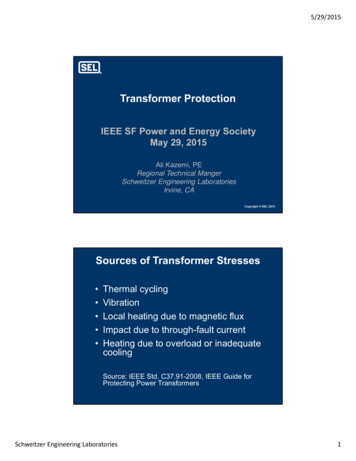
DG Interconnection ProtectionConventional DGIndustrial Gas TurbineReciprocating DieselReciprocating Gaseous FuelMicroturbine Gaseous FuelReciprocating aka: Internal Combustion Engine (ICE)7DG Interconnection ProtectionConventional DGFuel Cell84
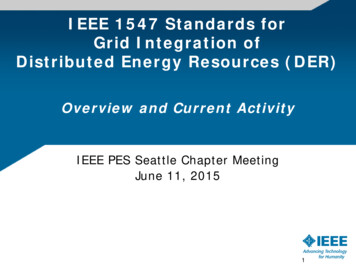
DG Interconnection ProtectionRenewable DGSolar (Thermal)Solar (PV)Small Hydro9DG Interconnection ProtectionRenewable DGWind May be induction orsynchronousgenerator outputMay be mixture ofgenerator andinverter outputBiogasBiomass105
DG Interconnection ProtectionRenewable DGBiodieselTidal11DG Interconnection ProtectionRenewable DGStorage Battery126
DG Interconnection ProtectionWhy Green Power ?(aka: Renewable Energy) Federal and State Governments Push for Renewable Resources“Green Power Is In.” Two Basic Penetration Drivers:1. PUC mandates that a percentage of generation is green by a givendate. This typically fosters installation of large blocks of green energyinstallation such as wind farms and large scale PV connected to transmissionsystems2. Increase the buy back rate and let market forces install greengeneration. This typically fosters smaller generators connected to distributionsystems. Technological advances have reduced green power costs13DG Interconnection ProtectionWhy DG: Utility Drivers T&D Issues– Decrease losses DG at the point of use is not subject to transport loss T&D losses range 3-7%– Demand Response (“Turn On Local DG to Turn Off Load to System”) No prebound/rebound effects in callable application Allows larger critical process C&I Customers to participate indemand response programs aka: Peak Reduction– Transmission decongestion– Distribution decongestion– Distribution build-out deferral147
DG Interconnection ProtectionReality of Grid Load Dynamics (Peak Demand)THIS IS THE MOST EXPENSIVE, INEFFICIENT, ANDENVIRONMENTALLY-DAMAGING POWER PER KWH OFELECTRICITY ACTUALLY CONSUMED Accumulated Annual Demand of Highest 5% occursabout 400 Hrs/Year100s of Billions of of equipment and capacity idle formost of the time15DG Interconnection ProtectionDG in a Demand Response Role Without DGDG With DG168
DG Interconnection ProtectionSustainability & Losses:Conventional Power Delivery525 kVABulk ssesDistributionLosses500 kVALoad Losses typically 3-7% 5% used in this example17DG Interconnection ProtectionSustainability & Losses:Use of DG at Load Heat rates (efficiency) of modern engine/gensets applied in DG systems are as good if not better thancombustion turbines (CTs) [1,2]. DG capacity has a heat rate of 9,800 btu/kWh saving approximately 2,200 btu/kWh of fuel input compared to theoverall peak power generation portfolio published by eGrid [3].[1] California Energy ent/reciprocating engines/reciprocating engines.html[2] California Energy Commission; ion turbines/combustion turbines.html[3] rid/index.html189
DG Interconnection ProtectionNon-Signaled Passive Demand Response:Rebound EffectRebound LoadCurtailed LoadTime of Day19DG Interconnection ProtectionSignaled Passive Demand Response:Prebound-Rebound Effect2010
DG Interconnection ProtectionSignaled DG-based Demand Response:No Prebound-Rebound Effects21DG Interconnection ProtectionWhy DG: Utility Drivers T&D Issues (con’t)– Grid Support Ancillary Serviceso Voltage regulation (1547A)o VAR Support (1547A)– Firming of Green Power Green power has intermittency issues Can be answered with fast syncing DGo Conventional DGo Storage– Ready and Standby Reserves Fast syncing prime movers Storage– Spinning Reserves Storage (as it is synchronized)2211
Why DG: Consumer DriversDG Interconnection Protection Rate Incentives Demand Reduction Interruptible Rates Load Curtailment Rates Energy Reduction (if power produced is less expensive thanUtility) Using renewable to offset energy costs Increase in CHP for greater fuel-to-power efficacy ( 90%possible)– CHP: Combined Cooling, Heating and Power Also called “TriGen” Uses cheap natural gas and heat recovery Power Security– Emergency Power Systems 1st rule of power quality, “you gotta have some” Emergency Power Systems cab be repurposed and usedfor demand rate reduction incentives23DG Interconnection ProtectionThe first rule of power qualityis you have to have it! Provide constant power through redundancy and faultelimination Redundancy is obtained by fault tolerant design Fault elimination attempts to design a “fault proof” system Emergency power systems used when the process oroperation cannot be interrupted Emergency power systems are designed for “MissionCritical Facilities” Mission Critical Facilities with Emergency Power Systemsare often planned or retrofit for operation in parallel withthe Utility for demand deduction2412
DG Interconnection ProtectionFault Tolerance:Utility Outages Employs redundant feeds from utility Still susceptible to outage from complete utility failure25DG Interconnection ProtectionFault Tolerance:Utility Outages Employ utility feed(s) and on-site power On-site power functional even in the event of totalutility failure1326
DG Interconnection ProtectionCritical Power Systems:Where Applied? Critical Service Sectors Network CenteredSectors Electric PowerIT and CommsBanking & FinanceOil and gasRail and AirWaterGovernmentLaw EnforcementEmergency ServicesHealth ServicesMunicipal ServicesNot a coincidence this is where much of the Utility Interconnected DG is installed27DG Interconnection ProtectionOn-Site Generation:Sustainability Times For outages greater than3 hours, fuel burning onsite generation isgenerally applied Short time outages maybe handled by electricalstorage, chemicalstorage or stored energy Reciprocating enginesare used most widely toprovide sustainable onsite power2814
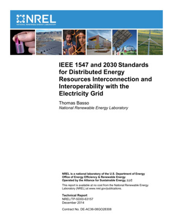
DG Interconnection ProtectionATS vs. Circuit BreakersUTILITYUTILITYMGGGLOADLOADATS Circuit BreakersATS does not protectATS cannot long-term parallelCircuit Breakers cost more than an ATS, but provideprotection and operational flexibility29DG Interconnection ProtectionConversion of ATS-based emergency system todual purpose emergency and “bumpless” peakshaving systemUTILITYUTILITYMGGGLOADExisting FacilityLOADFacility Retrofit with Switchgear/Protection/Controls for Grid ParalleledGenerator Operation3015
DG Interconnection ProtectionGreenfield dual-purpose emergency and“bumpless” peak shaving system31DG Interconnection ProtectionComplex Application:Dual Fed Facility Main-Tie-Main3216
DG Interconnection ProtectionPrime Power (No Utility Connection) On-Site Generation is supplying the Facility without any connection to theUtility. Off-Grid Power Emergency Power (Standby)Generation is controlled to maintain a constant speed (frequency) and voltage.As the isolated Facility’s load changes, the generator must alter its output forboth the real load (watts) and reactive load (VARs). The control system willaccomplish this to the limits of the generation. As real power demand (watts) increases, the governor is signaled to increase thefuel to the generation to maintain rated frequency output. As real power demand (watts) decreases, the governor is signaled to decreasethe fuel to the generation to maintain rated Hz frequency output. As reactive power demand (VARs) increases, the voltage regulator is signaled toincrease the field current, thereby increasing VAR output to maintain rated voltage. As reactive power demand (VARs) decreases, the voltage regulator is signaled todecrease the field current, thereby decreasing VAR output to maintain ratedvoltage.33DG Interconnection ProtectionParalleled Operation (Interconnected to Utility) On-Site Generation and Utility are operating in parallel to supply the FacilityOff-Grid Power Load Management (Peak Shaving) Transfer Transition (Short or Long Term)Generation is controlled to maintain real power and reactive power outputper watt and power factor setpoints respectively.As the Utility interconnected Facility’s load changes, the generator mustalter its output for both the real load (watts) and reactive load (VARs). As real power demand (watts) increases, the governor is signaled toincrease the fuel to the generator per the watt output setpoint. As real power demand (watts) decreases, the governor is signaled todecrease the fuel to the generator per the watt output setpoint. As reactive power demand (VARs) increases, the voltage regulator issignaled to increase the field current, thereby increasing VAR outputto maintain power factor per the setpoint. As reactive power demand (VARs) decreases, the voltage regulator issignaled to decrease the field current, thereby decreasing VAR outputto maintain power factor per the setpoint.1734
DG Interconnection ProtectionMonthly Demand: Facility and Supplying UtilityUtility Demand10,000MW on 7/27@ 6-7 PM10,000Facility DemandLimited to 700kW1,0005,000MWkWFacility LoadUsing Generator500123456789Utility Total System LoadNon-Coincident Peak(NCP) Rate Cost Saving11 13 15 17 19 21 23 25 27 29 3110 12 14 16 18 20 22 24 26 28 30July35DG Interconnection ProtectionMWUtility’s Energy Total System LoadkWFacility LoadMonthly Demand: Facility and Supplying Utility3618
DG Interconnection ProtectionConsumer Demand Reduction StrategiesNo electrical export to Utility37DG Interconnection ProtectionConsumer Demand Reduction StrategiesNo electrical export to Utility1938
DG Interconnection ProtectionOperational Sequence Details Emergency PowerLoad IsolationLoad FollowingExport To know how DG is contr
- IEEE 1547: Industry DG Guide - Sample Utility DG Interconnection Guide DG Interconnection Protection 1 Presentation Objectives Interconnection Protection: “The Five Food Groups” Interconnection Transformer Impacts Generator Types and Impacts Synchronous Induction Asynchronous (Inverter Based) Example Protection Applications Distribution Protection Coordination Issues Smart .