Transcription
LAPPEENRANTA UNIVERSITY OF TECHNOLOGYFaculty of TechnologyLUT EnergyHEAT EXCHANGERDIMENSIONINGJussi Saari1
TABLE OF CONTENTS1INTRODUCTION .72GENERAL BACKGROUND.82.12.23BASIC ISSUES OF HEAT EXCHANGER DESIGN .8HEAT EXCHANGER DESIGN PROCESS .9TYPES OF HEAT EXCHANGERS.123.1 FLOW ARRANGEMENTS .123.1.1Basic single-pass arrangements .123.1.2Multipass arrangements.143.2 COMMON TYPES OF PHYSICAL CONSTRUCTION .163.2.1Tubular –double-pipe .173.2.2Tubular –shell and tube .173.2.3Plate heat exchangers.213.2.4Spiral heat exchanger .253.2.5Compact heat exchangers .253.3 SELECTION OF APPROPRIATE HEAT EXCHANGER TYPE .273.3.1Fluid pressures and temperatures .273.3.2Fouling.283.3.3Material choices.293.3.4Cost.304METHODS OF HEAT EXCHANGER CALCULATION .314.1 QUICK ESTIMATES .344.2 LOGARITHMIC MEAN TEMPERATURE DIFFERENCE (LMTD) METHOD .354.2.1Definition of LMTD .354.2.2Complex flow arrangements.384.2.3Special Cases .414.2.4Summary .414.3 ε-NTU -METHOD .424.3.1Dimensionless parameters: ε, C* and NTU .424.3.2Effectiveness –NTU relationships.444.3.3Summary .504.4 P-NTU -METHOD .535OVERALL HEAT TRANSFER COEFFICIENT .555.15.26DEFINITION .55U-VALUE OF EXTENDED-SURFACE HEAT EXCHANGERS .57HEAT TRANSFER AND PRESSURE DROP CORRELATIONS .606.1 A BRIEF INTRODUCTION ON CONVECTION HEAT TRANSFER .606.1.1Dimensionless parameters .616.1.2Analogy of friction and heat transfer: practical consequences .636.2 SOLVING CONVECTION HEAT TRANSFER COEFFICIENT FROM EMPIRICAL CORRELATIONS .646.3 INTERNAL FLOW IN A PIPE .666.3.1Fully developed turbulent flow.686.3.2Fully developed laminar flow.706.3.3Entry length.716.4 FLOW ACROSS TUBE BUNDLES .726.4.1Plain tubes .736.4.2Finned tube banks.756.4.3Shell-side flow in a shell-and-tube exchanger.776.5 PLATE HEAT EXCHANGER SURFACES .806.5.1Gasketed plate heat exchangers .802
6.5.2Spiral heat exchangers.816.6 COMPACT HEAT EXCHANGER SURFACES .817PRESSURE DROP.837.1 PRESSURE DROP CALCULATION –GENERAL PRINCIPLE .847.1.1Core entrance pressure drop.847.1.2Core pressure drop.857.1.3Core exit pressure drop .877.1.4Total pressure drop .877.2 PRESSURE DROP IN SPECIFIC TYPES OF HEAT EXCHANGER .887.2.1Tubular heat exchangers, outside flow .887.2.2Gasketed plate heat exchangers .928FOULING.948.1 FOULING PROCESS .948.1.1Rate of fouling.958.1.2Effects of operating parameters on fouling .968.2 ACCOUNTING FOR THE EFFECTS OF FOULING .973
NOMENCLATURESYMBOLSRomanABcC tarea [ m2 ]width [ m ]specific heat [ J / kgK ]heat capacity rate [ W / K ]ratio of heat capacity rates in ε-NTU method. [-]Fanning friction factor (coefficient of friction) [ - ]diameter [ m ]hydraulic diameter [ m ]surface roughness [ m ]Darcy (Moody) friction factor [ - ]correction factor in logarithmic mean temperature difference method [-]1. mass velocity [ kg / m2s ]2. conductance [ W / K ]convection heat transfer coefficient [ W / m2 K ]Colburn j-factor, St Pr2/3 [ - ]thermal conductivity [ W / mK ]unit resistance [ - ]length [ m ]mass [ kg ]mass flow rate [ kg / s ]Number of Transfer Units, (dimensionless conductance), [ - ]Nusselt number [ - ]pressure [ Pa ]1. temperature effectiveness [ - ]2. power [ W ]Prandtl number [ - ]heat transfer rate [ W ]heat flux [ W / m2 ]volume flow rate [ m3 / s ]radius [ m ]1. (thermal) resistance [ K / W ]2. ratio of heat capacity rates in logarithmic mean temperature differencemethod or P-NTU method. [-](thermal) resistance per area [ m2 K / W ]1. R”tc contact resistance per area [ m2 K / W ]2. R”f fouling resistance per area [ m2K / W ]Reynolds number [ - ]1. wall thickness [ m ]2. fin spacing [ m ]spacing [m]Stanton number [ - ]thickness [ m ]4
TUvwtemperature [ K ]overall heat transfer coefficient [ W / m2K ]specific volume [ m3 / kg ]flow velocity [ m / s ]Greekαβδερηfηoηpµντthermal diffusivity, α k / ρcp [m2 / s ]heat transfer area per volume [m2 / m3]gap between the plates of a plate or spiral heat exchanger [ m ]heat exchanger effectiveness [ - ]density [ kg / m3 ]fin efficiency [ - ]overall surface efficiency [ - ]pump/fan efficiency [ - ]dynamic viscosity [ Pa s ]kinematic viscosity [ m2 / s ]shear stress [N / m2]SUPERSCRIPTS’’’’’’*per lengthper areaper age1. cold side of heat exchanger2. core of the heat exchangerdiagonalentry to heat exchanger core1. fouling2. fin3. fluidfree-flowfrontalhot side of heat exchanger1. inlet2. insidelongitudinallogarithmic mean1. mass2. mean3. modified5
maxminopradstTtbwmaximumminimum1. outlet2. HETEMABaffle CutCross-CorrugatedCross-WavyHeating, Ventilating and Air ConditioningHeat ExchangerLogarithmic Mean Temperature DifferenceMean Temperature DifferenceNumber of Transfer UnitsPlate Heat ExchangerTubular Exchanger Manufacturer’s Association6
1 INTRODUCTIONThe purpose of this design guide is to give the reader a general idea of the problem fieldof heat exchanger design, sizing and optimizing. Emphasis is on thermo-hydraulicdesign of the heat exchanger; mechanical design and system optimization are beyondthe scope of this guide.Only recuperators, or heat exchangers where two fluids are separated by the heattransfer surface that normally has no moving parts, are covered. This restriction ofscope leaves out regenerators – heat exchangers where the heat transfer is performedthrough a material that is alternately brought to contact with hot and cold streams,storing energy from the hot stream and releasing it into the cold one. Boilers andcondensers are also left outside of the scope of the guide.7
2 GENERAL BACKGROUNDAn overview of heat exchanger design problems, a summary of key issues to cover inthe design process, and a design methodology of heat exchangers is presented in thischapter.2.1 BASIC ISSUES OF HEAT EXCHANGER DESIGNApplications of heat exchangers present two distinct categories of design problems(Sarkomaa 1994):1. Design and optimization of mass-produced heat exchangers, e.g. automobileradiators, heat exchangers of HVAC equipment, oil cooling heat exchangersfor machinery, etc.2. Design and optimization of heat exchangers manufactured as one-off, or atmost in small series, for a specific application.As the production runs of first group of heat exchangers are often measured inthousands or more, a very careful and detailed optimization of their technical andeconomical characteristics can be worthwhile if even only very small improvementscan be achieved. Heat exchangers in the second problem category, on the other hand,must often be designed to be functional and economical in their intended use on thebasis of sometimes rough or incomplete data, which makes overly detailed and carefuloptimization procedures impractical.The following chapters are written mostly with the second types of design andoptimization problems in mind. Typical characteristics for these cases include poorknowledge of the exact types of fluid flows and their properties and foulingcharacteristics, and that those characteristics as well as the mass flow rates mayfluctuate depending on changes in the production and process environment.At least the following issues should usually be considered when designing a heatexchanger (Sarkomaa 1994):1. Fouling: The heat exchanger must fulfil process requirements after fouling. Ifpossible, the heat exchanger should be designed to be self-cleaning, in otherwords so that the growth rate of fouling layer will slow down and eventuallystop at a certain level. Whether this is possible or not, fouling must beconsidered so that at the end of a period of use when maintenance isperformed, the heat exchanger still achieves the required heat duty.Sometimes determining sufficient excess heat transfer area or additional heatexchangers to take into account the effects of rapid fouling processes canmake up a significant part of the whole heat exchanger design problem.8
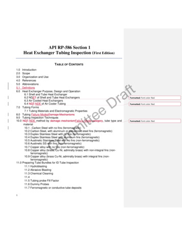
2. Environment of use: The heat exchanger must be designed in accordance tothe environment where it will be used, so that in addition to the mechanicaland thermal stresses of normal use, the heat exchanger is also designed againstdamage that could result from issues related to transportation, installation,process start-up and run-down as well as likely misuse or accident scenarios.3. Maintenance: The heat exchanger should be easily maintainable. In practicalterms this means ease of cleaning, easy removal of especially those partslikely subjected to significant fouling, erosion, corrosion, vibrations, creep, orother forms of damage or decay. Maintainability is also connected to theenvironment of use, for example in space requirements around the heatexchanger for maintenance and possibly accessibility for and proximity oflifting and moving equipment at the site.4. Flexibility: Sometimes, for example if the mass flow rates of the fluids canvary greatly, it may be necessary to allow for considerable adjustments in useof the heat exchanger,. This can sometimes require the heat transfer area to bedivided between parallel heat exchangers separated with valves.5. Limitations of mass and dimensions: The dimensions and mass of the heatexchanger may be limited not only by the usage environment, but alsoequipment and locations related to manufacture, transportation, moving,lifting or maintenance.6. Minimizing the cost: The goal of heat exchanger selection and design isalways to minimize the cost. The main cost-related parameter is often the totalheat transfer area. To minimize the heat transfer area typically meansmaximizing the fluid velocities within the limitations set by pressure drop,erosion and vibrations. Additional cost-related issues include pumping cost tocounter the pressure drops, maintenance costs, and production losses due tomaintenance or unreliability.2.2 HEAT EXCHANGER DESIGN PROCESSThe process of heat exchanger design is in most sources (Taborek 1983a, Sarkomaa1994, Sekuli 2003) described to follow through roughly the following steps:1.2.3.4.5.Problem definition: design specificationsSelection of heat exchanger typeThermo-hydraulic designMechanical designManufacturing, cost and process optimization considerations.The steps are rarely entirely sequential; results from various steps frequently haveinfluence on choices made previously, and typically several iterations must be madebefore a final acceptable design is completed. The influences and feedbacks between9
different steps are clearly seen in Figure 2.1 (adapted and simplified from Sarkomaa1994 and Sekuli 2003).1. Problem definitionConsidering2. Selection of heat exchanger type3. Assume values for initial design parameters4. Determine the heat transfer area A required (Ch.4)9. Evaluation of the pressure drops of both streamsAcceptable?NoYes10. Evaluation of the heat exchanger against othercriteria (for example mechanical rigidity, erosion,vibrations, dimensions and weight, cost, fouling )Acceptable?NoYesFinishFigure 2.1 Process of heat exchanger design, adapted and simplified from (Sarkomaa 1994) and (Shah2003).10
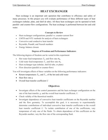
The emphasis in the following chapters will be on the second and particularly the thirdsteps. Issues related to heat exchanger type selection will be discussed in chapter 3.3,after the basic heat exchanger types have been covered.Similar stages must usually be considered even if the requirement for a heat exchangercan be fulfilled by simply finding a suitable mass-produced heat exchanger fromvendors’ catalogues. This is often the case if the requirement is for a small heatexchanger manufactured of stainless or carbon steel. These are typically mass producedin very large quantities, and due to mass produced quantities costs are typically low anddelivery times short.From the purchasers point of view the relevant thermo-hydraulic design problem is thenthat of rating problem, that is, where from input data of exact flow arrangements,dimensions, geometry, surface and material properties, and fluid flow data (inlettemperatures, mass flow rates and property and fouling data) one calculates the fluidoutlet temperatures, total heat transfer rate, and pressure drop characteristics of the heatexchanger in the expected situations where the heat exchanger may be needed.If the heat exchanger requirement is for a larger heat exchanger of 10.20 m2 or moreheat transfer area, and particularly if the requirement includes special characteristics, aheat exchanger may need to be designed specifically for such requirements. In suchcases one faces a sizing problem, described in Fig. 2.2.Input DataFluid mass flow ratesInlet pressuresInlet temperaturesFluid propertiesFouling characteristicsHeat exchanger type and flowarrangementsDesign CalculationsBasic heat exchangerdesign methodHeat transfer correlationsOutput DataOutlet temperaturesOutlet pressuresTotal heat transfer ratePressure drop correlationsFigure 2.2. Input and output data for heat exchanger thermo-hydraulic sizing problem; adapted from(Sarkomaa 1994).Sizing can be performed in various levels of detail, typically starting from a roughestimation for the magnitude of required heat transfer area, and followed by either asizing calculation with some of the more detailed design methods for thermo-hydrauliccalculation of heat transfer performance, and/or or with numerical computational fluiddynamic (CFD) software.The emphasis in the following chapters is in presenting methods for reasonablyaccurate design of heat exchangers that can be applied either by hand or utilized incomputer programs.11
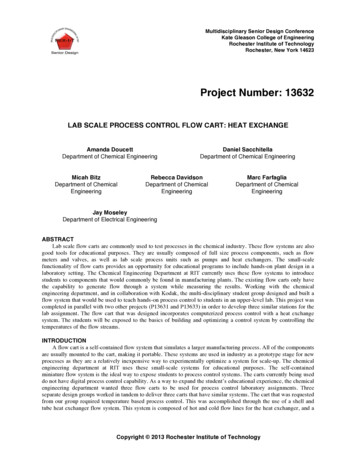
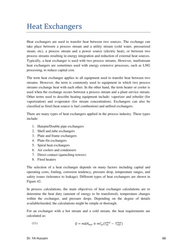
3 TYPES OF HEAT EXCHANGERSHeat exchangers can be designed to accomplish numerous flow arrangements and withcountless construction methods and geometries. A few basic types make up theoverwhelming majority of heat exchanger market, however, and only the mostcommonly used configurations will be covered in the following chapters.Chapter 3.1 explains the basic flow arrangements and the concept of multi-passing.Chapter 3.2 deals with the most common types of heat exchanger construction, and alsocover the specific details and peculiarities of flow arrangement pertinent to each type ofheat exchanger. Finally Chapter 3.3 will give a set of very general guidelines onselecting an appropriate type of heat exchanger and suitable material given the specificsof the application.3.1 FLOW ARRANGEMENTSThe arrangement of hot and cold fluid flows relative to each is important for howefficiently the heat transfer area of the heat exchanger can be used to transfer therequired heat load. Besides the efficient usage of heat transfer area, other considerationsin the selection of flow arrangement include for example pressure drop considerations,header design, allowable thermal stresses on the heat exchanger materials, and issuesrelated to the end use location and plumbing.3.1.1Basic single-pass arrangementsThe two simplest flow arrangements possible in heat exchangers are counter-flow, andparallel-flow. These and the resulting hot- and cold-fluid temperature profiles in asimple double-tube heat exchanger with tube length L are demonstrated in Figure 3.1.As is evident from the temperature profiles, the counter-flow arrangement will enablemore heat transfer with given inlet temperatures, and also enables moderate heattransfer rates to be achieved at smaller area due to avoiding the problem of diminishingtemperature difference in the parallel-flow arrangement. Besides problem ofdiminishing temperature difference at the outlet end, an additional disadvantage of theparallel-flow arrangement is the very large temperature difference at the inlet end,which may create problematically high thermal stresses in some situations.12
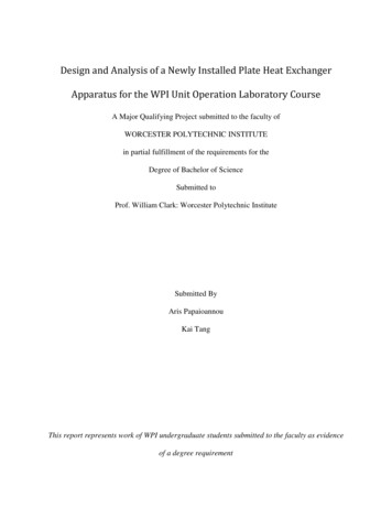
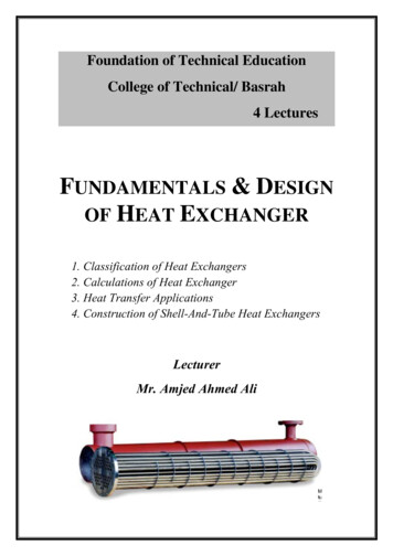
Figure 3.1. Basic double-tube heat exchanger in counter-flow (left) and parallel-flow (right)configurations.The advantages of parallel-flow arrangement are few, but in some cases important. Themain advantage is the typically more uniform heat transfer surface temperaturedistribution. This can be advantageous if both fluids are fairly hot, where parallel-flowarrangement provides lower maximum temperature of heat transfer surface. If thisallows a cheaper material to be used, it may outweigh the disadvantage of needing moreheat transfer area than other flow arrangements would.The higher minimum temperature may also sometimes be advantageous, for example toprevent the freezing of the warmer fluid if it is a liquid near it’s freezing point, or toprevent the condensation of acid vapours at the surface if the warmer fluid is a gas thatcontains acids. Issues such as convenient plumbing of inlet and outlet flows at theinstallation site may also sometimes outweigh the importance of efficient heat transferarea usage. Particularly if the required heat transfer rate is much less than maximumpossible rate allowed by the fluid flow rates and temperatures, this disadvantage ofparallel-flow arrangement becomes small.The third basic flow arrangement possibility is cross flow. In a cross-flow arrangementit is also significant whether the flows are mixed or unmixed; that is, if the fluid is ableto mix freely in direction transverse to the flow direction, or if it’s movement ischannelled by the heat exchanger design in a way that prevents such mixing. This isdemonstrated in Figure 3.2.In the left-side example of Figure 3.2 the fluid flowing across the tube bundle isconsidered mixed, but the fluid in the tubes is prevented from mixing because of thetubes. Usually if there are at least four or five rows of tubes in the flow direction of thefluid moving across the tube bundle, the tube-side fluid can be considered completelyunmixed (Shah 2003,pp.61). On the other hand, if there were only one row of tubes,then clearly the fluid in tubes should be considered mixed, and cases in between (fromtwo up to four or five rows) the tube-side fluid should be considered to be partiallymixed.13
Figure 3.2. Cross-flow arrangements: one fluid mixed, one unmixed (left) and with both fluids unmixed(right).Temperature distributions of inlet and outlet fluid flows for mixed-unmixed andunmixed-unmixed cross-flow heat exchangers are demonstrated in Fig. 3.3. The coldflow is assumed unmixed in both cases; hot fluid is unmixed in the left, mixed in theright-side example.Figure 3.3. Temperature profiles at inlet and outlet of unmixed-unmixed and mixed-unmixed cross-flowheat exchangers.Cross-flow arrangement does not provide quite as efficient use of heat transfer area ascounter-flow does, but unless a very high heat transfer rate (near the maximum possiblewithin the boundaries of 2nd law of thermodynamics) is required, it’s performance is notmuch worse. It is frequently much easier to design uncomplicated headers that producean even flow distribution for a cross-flow than for a counter-flow arrangement. Due toheader design issues plate-type counter-flow heat exchangers frequently have sectionsof cross-flow pattern at the inlet and outlet headers.3.1.2Multipass arrangementsSometimes it is useful to arrange one or both fluids to pass through the heat exchangermore than once. From thermal performance point of view, one of the fluid flowspassing through the exchanger more than once doesn’t yet necessarily mean that theheat exchanger should be considered a multi-pass one, however: a true multi-passconfiguration exists only if it is not possible to “fold”the heat exchanger into a single-14
pass one. This is demonstrated in Figure 3.4, where the left-side example is a truemulti-pass heat exchanger (two-pass cross-counterflow), but the one on the right side isin fact a one-pass cross-flow heat exchanger.Figure 3.4. Multipassing: a two-pass cross-counterflow heat exchanger (left), and one-pass cross-flowheat exchanger.The reason why the right-side example cannot be considered a true multi-pass heatexchanger is obvious, if one imagines what would happen if the heat exchanger was cutin half between the downwards- and upwards-going flows demonstrated by the thickgray arrows. If the right-side half would be swung down and to the left along animaginary hinge in the bottom, it is clear that the flow patterns of the two fluids relativeto each other would not change, but the geometry would become a clear one-passarrangement. With the left-side example no such cut-and-swing that would make theheat exchanger into a single-pass one is possible; therefore it represents a true multipass heat exchanger.It is also evident from the figure that when the fluid represented by thick gray arrowsre-enters the heat exchanger on the left side example, the fluid flow across it will be at adifferent temperature than it was in the first pass, which is not the case in the right-sideexample – another sign that shows that only the left-side example can be considered amulti-pass unit.Arranging a one-pass heat exchanger as in the right-side example of Fig 3.4 cansometimes be necessary for example in order to fit the heat exchanger to the space andshape requirements of an installation site. With true multipassing on the other hand it ispossible to change the nature of a single-pass cross-flow heat exchanger a towardscounter-flow or parallel-flow arrangements.Particularly if a very high heat transfer rate (relative to the maximum possible with theavailable temperature differences and flow rates) is required, a choice of cross-flowinstead of counter-flow may demand a significant increase of heat transfer area, but atthe same time pure counter-flow heat exchanger is sometimes problematic to designheaders for; in such a case a multi-pass cross-counterflow arrangement will provide alower heat transfer area requirement than a single-pass crossflow would, but still allows15
the designer to take advantage of the easy header design of crossflow exchangers.Likewise cross-parallelflow may allow a convenient balance of the more efficient usageof heat transfer area of cross-flow geometry with the advantages that sometimes maymake a parallel-flow design desirable.If the flow arrangement corresponds to a cross-counterflow or cross-parallelflowarrangement, then the heat exchanger will need to be analyzed in stages; a two-passcross-counterflow arrangement of Figure 3.4 for example could be presented as acombination of two heat exchangers in series (Figure 3.5 a). If the number of passes nis greater than two (Fig 3.5 b), the performance of the series of cross-flow exchangersapproaches that of a single counterflow exchanger as n approaches infinity.(a)(c)(b)Figure 3.5. Splitting multi-pass heat exchanger into multiple 1-1 –single-pass heat exchangers foranalysis: a) 1-2, b) 1-n and c) 2-2 –heat exchangers.Finally it is naturally also possible to pass both fluids several times through a heatexchanger; an example of a 2-2 –heat exchanger broken up into a network of fourindividual heat exchangers is given in Fig. 3.5 c.3.2 COMMON TYPES OF PHYSICAL CONSTRUCTIONThe most critical decision when designing a heat exchanger is the selection of the basictype of heat exchanger to design. Various criteria dictate the selection of the suitabledesign, and some constructions (particularly the shell-and-tube) may be designed toadequately serve in a wide variety of situations. The tubular heat exchanger types areoften tempting choices not only for their suitability for a given task, but also for theease of design: the double-tube heat exchanger is probably the simplest possibleconstruction, while the shell-and-tube exchanger has had a number of tried and testeddesign methods developed for it due to it being the most common heat exchanger typein process industry. The cost of finding the easiest route may be considerable however;16
in those situations where other types of heat exchangers would cope, they often wouldprovide considerably smaller and cheaper options to the tubular exchangers.3.2.1Tubular –double-pipeA double-pipe heat exchanger (Figure 3.6) is perhaps the simplest type of heatexchanger possible, consisting of just two concentric tubes, and appropriate end fittingsto move the fluids from one section of the exchanger to the next. If one or the otherfluid has much lower heat transfer coefficient, the inner tube can be equipped withlongitudinal fins on inner or, more commonly, external surface.Figure 3.6. Double-pi
The purpose of this design guide is to give the reader a general idea of the problem field of heat exchanger design, sizing and optimizing. Emphasis is on thermo-hydraulic design of the heat exchanger; mechanical design and system optimiza