Transcription
Foundation of Technical EducationCollege of Technical/ Basrah4 LecturesFUNDAMENTALS & DESIGNOF HEAT EXCHANGER1. Classification of Heat Exchangers2. Calculations of Heat Exchanger3. Heat Transfer Applications4. Construction of Shell-And-Tube Heat ExchangersLecturerMr. Amjed Ahmed Ali
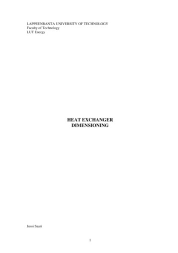
Heat ExchangerCollege of TechnicalHEAT EXCHANGER1 PREFACEA Heat Exchanger: heat energy is transferred from one body or fluid stream toanother. heat transfer equations are applied to calculate this transfer of energy so as tocarry it out efficiently and under controlled conditions. The equipment goes undermany names, such as boilers, pasteurizers, jacketed pans, freezers, air heaters,cookers, ovens and so on. The purpose of the heat exchanger is :1. To heat or cool a stream flowering from equipment to another.2. To vaporize a liquid stream3. To condensate a vapor stream.2 CLASSIFICATION OF HEAT EXCHANGERS:2.1. TYPES OF APPLICATIONa. Boilers and Steam Generatorsb. Condensersc. Radiatorsd. Evaporatorse. Cooling towers (direct contact)f. Regenerators (periodic heat flow hot and cold fluid alternately occupythe space of the heat exchanger)g. Recuperates (continuous heat flow hot and cold fluid are separated bya wall–shell and tube heat exchangers)2.2 FLUID FLOW ARRANGEMENTa) Co-current or parallel flow : The fluids can flow in the same directionthrough the equipmentb) Countercurrent flow: The fluids can flow in the opposite directionsthrough the equipmentc) Cross flow: they can flow at right angles to each other.Mr. Amjed Ahmed2
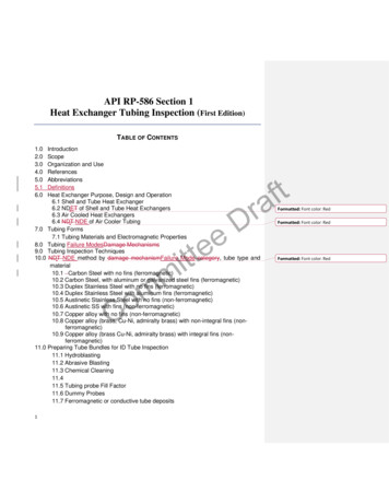
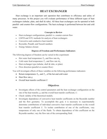
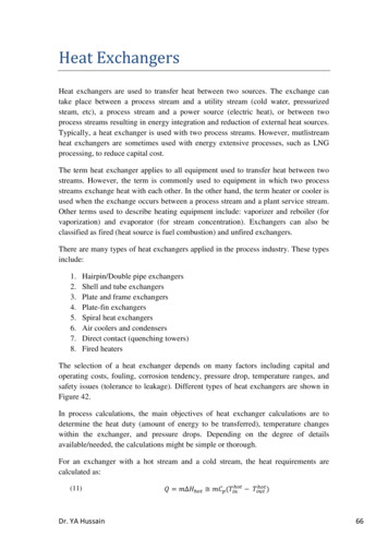
Heat ExchangerCollege of TechnicalFig.(1) Double Pipe Heat Exchanger2.3 Mixed and Unmixed fluid:a. Both fluids unmixedb. One fluid mixed another unmixedc. Both fluids mixedFig.(2) Mixed and Unmixed fluid3 CONTINUOUS-FLOW HEAT EXCHANGERSIt is very often convenient to use heat exchangers in which one or both of thematerials that are exchanging heat are fluids, One of the fluids is usually passedthrough pipes or tubes, and the other fluid stream is passed round or across these.Most actual heat exchangers of this type have a mixed flow pattern, but it is oftenpossible to treat them from the point of view of the predominant flow pattern.3.1 DOUBLE-PIPE HEAT EXCHANGERA double-pipe heat exchanger is constructed from two pipes, one inside theother. First fluid flows inside the inner pipe while the second fluid flows in theannular space between the two pipes. To obtain larger heat exchange area, severalpipes are arranged side-by-side and fittings are attached to allow the fluids to contactthe pipes in series.Fig.(3) Double-Pipe Heat exchanger3.2 SHELL-AND-TUBE HEAT EXCHANGERIf very large heat exchange areas are required. Shown below is a bundle ofsmall-diameter tubes which are arranged parallel to each other and reside inside amuch larger-diameter tube called the "shell", much like strands of uncooked Spagetticome in a tube-shaped container. The tubes are all manifolded together at either endso1-1 Heat Exchanger that the "tube fluid" enters the left side and is distributedequally among all the tubes. At the right side, the fluid exits from each tube, is mixedtogether in a second manifold, then leaves as a single stream. The second fluid flowsin the space in between the outside of tubes. Baffle plates inside the shell force theshell fluid to flow across the tubes repeatedly as the fluid moves along the length ofthe shell.1-2 Heat Exchanger Half of the tubes have flow from left to right while theMr. Amjed Ahmed3
Heat ExchangerCollege of Technicalother half have flow in the opposite direction.1 pass of shell-1 pass of tubes1 pass of shell-2 pass of tubes2 pass of shell-4 pass of tubesFig.(4) Different type of shell and tube Heat exchangerMr. Amjed Ahmed4
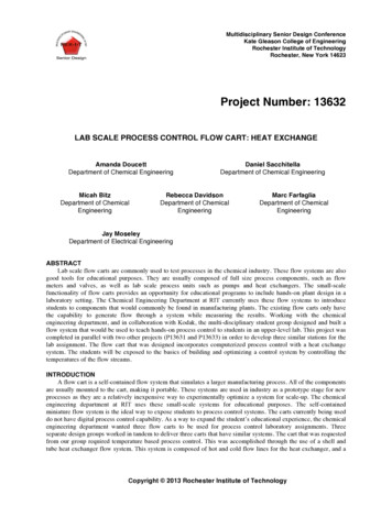
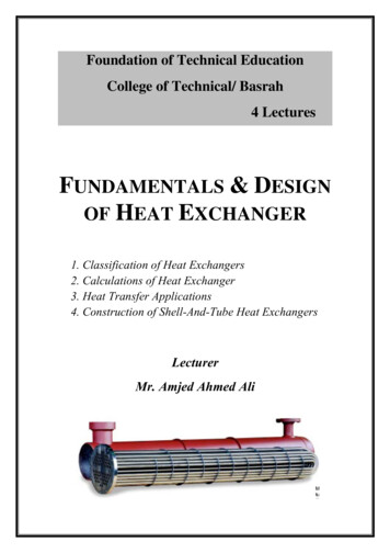
Heat Exchanger4 TYPESCollege of TechnicalOF HEATING ANDCOOLING CURVES:Th inTh outTc outTc inTh outTh inTh inTc outTh outTc inTc out(c) Ch Cc or a condensing vaporTh inCondensingTc outEvaporatingTc in(d) Ch Cc or an evaporating liquidDesuperheatingSubcoolingTh out Th inTc in Tc out(e) Hot and cold fluid Changing phaseCoolingTh outHeating(g) cold fluid Changing phasePartialTc outEvaporatingTc inTc inCondensingTc outSuperheatingHeatingTh out(f) Hot fluid Changing phaseTh inTh inCondensingHeatingTh outTc in(h) condensable and noncondensablecomponentsFig(11) Temperature distribution for a different counter current heat exchanger.Mr. Amjed Ahmed5
Heat ExchangerCollege of Technical4 HEAT TRANSFER CALCULATIONSThe primary objective in the thermal design of heat exchangers is to determinethe necessary surface area required to transfer heat at a given rate for given fluidtemperatures and flow rates. the fundamental heat transfer relationq UA T(1)the overall heat transfer coefficient U is proportional to the reciprocal of thesum of the thermal resistances. For the common configurations which we shallencounter; cylindrical wall:Uo 11 ro ro ro 1 ln ho k ri ri hi1 ri 1 ri ro 1 ln ro ho k ri hiUA UoAo UiAiUi (2)(3)where subscripts i and o represent the inside and outside surfaces of the wall,respectively, the overall heat transfer coefficient and the surface area must becompatible, i.e.,q UoAo T UiAi T(1)Table(1) gives approximate values of U for some commonly encountered fluids.The wide range of values cited results:1. A diversity of heat exchanger materials (of different k value)2. A flow conditions (influencing the film coefficients, h),3. Geometric configuration.Mr. Amjed Ahmed6
Heat ExchangerCollege of TechnicalTable(1) Overall Heat Transfer CoefficientFouling ResistanceThe performance of heat exchangers depends upon the heat transfer surfacesbeing clean and uncorrected. Should surface deposits be present, thermal resistanceincreases, resulting in decreased performance. This added resistance is usuallyaccounted for by a fouling factor (Fouling Resistance, Rf) which must be includedalong with other thermal resistances when calculating the overall heat transfercoefficient.1 r 1r r r 1 R fo o ln o o R fi o hok ri ri ri hi1Ui ri 1 ri r r 1 R fo i ln o R fi k ri hi ro ho ro Uo (4)(5)Typical values of R, (m2.K/W) range from 0.00009 for clean vapors to 0.0002for hot river water.1. Material deposits on hot surfacesMr. Amjed Ahmed7
Heat ExchangerCollege of Technical2. Rust impurities3. Strong effect when boiling occursRfoRfiCleanAfter some timeFig.(5) fouling resistance in double pipe heat exchanger5 LOG-MEAN TEMPERATURE DIFFERENCE(LMTD METHOD)5.1 DOUBLE-PIPE HEAT EXCHANGERA parallel-flow flat-plate exchanger, whose temperature profiles are shown inFig.(2) We shall assume that:1. U is constant2. heat exchange takes place only between the two fluids3. the temperatures of both fluids are constant over a given cross-section4. the specific heats of the fluids are constant T1 T2dAFig.(6) The T1 and T2 expressions in parallel-flow and counter-flow heatexchangerMr. Amjed Ahmed8
Heat ExchangerCollege of Technicalthe heat transfer between the hot and cold fluids for a differential length dx isdq UdA(Th-Tc)(6)since dA is the product of length dx and a constant width. The energygained by the cold fluid is equal to that given up by the hot fluid,dq mcCcdTc -mhChdTh(7)where m is the mass flow rate and C is the specific heat. Solving for thetemperature differentials from equation (7),dTc dqmcCcdTh dqmhChTaking Their difference, we get;dTh dTc dq(11) mh C h mc Cc(8)Eliminating dq between (6) and (8) yieldsd (Th Tc ) UA(Th Tc )(11) m h C h mc C c(9)2d (Th Tc )11) UA( (Th Tc )m h C h mc C c1 which integrates to give(10)where the T terms are as shown in Fig. (5). And From an energy balance oneach fluid,and substitution of these expressions into (10) givesor, in terms of the differences in end temperatures,(11)Upon comparing this result with eq.(1) , we see that T Mr. Amjed Ahmed T2 T1 Tlmln( T2 / T1 )9
Heat ExchangerCollege of TechnicalThis average effective temperature difference is called the log-meantemperature difference (LMTD). It can easily be shown that the subscripts 1 and 2may be interchanged without changing the value of Tlm.5.2 MULTIPASS AND CROSS-FLOW HEAT EXCHANGERSFor more complex heat exchangers, such as those involving multiple tubes,several shell passes, or cross flow, determination of the average effective temperaturedifference is so difficult that the usual practice is to modify (1) by a correction factor,givingq UAF Tlm(1.3)Correction factors F for several common configurations are given in Fig.(6). Inthese figures the notation (T1,T2 , t1, t2 ) to denote the temperatures of the two fluidstreams has been introduced, since it is immaterial whether the hot fluid flows throughthe shell or the tubes.It is normally correlated as a function of two dimensionless temperature ratios:Mr. Amjed Ahmed10
Heat ExchangerMr. Amjed AhmedCollege of Technical11
Heat ExchangerMr. Amjed AhmedCollege of Technical12
Heat ExchangerCollege of TechnicalEXAMPLE 1In a counter flow heat exchanger, water is being chilled by a sodium chloridebrine. If the rate of flow of the brine is 1.8 kg/s and that of the water is 1.05 kg/s ,estimate the temperature to which the water is cooled if the brine enters at -8 C andleaves at 10 C, and if the water enters the exchanger at 32 C. If the area of the heattransfer surface of this exchanger is 55 m2, what is the overall heat-transfercoefficient? Take the specific heats to be 3.38 and 4.18 kJ/kg C for the brine and thewater respectively.SolutionBy heat balance,heat loss in brine heat gain in water1.8 x 3.38 x [10 - (-8)] 1.05 x 4.18 x (32 - Tw2)Tw2 7 C.for counterflowTherefore T1 [32 - 10] 22 C and T2 [7 - (-8)] 15 C. Tm (22 - 15)/ln(22/15) 18.3 C.q UA Tm3.38 x 1.8 x 18 U x 55 x 18.3U 0.11 kJ/m2 CEXAMPLE 2Determine the heat transfer surface area and length required for a heatexchanger constructed from a 0.0254m OD tube to cool 6.93 kg/s of a 95% ethylalcohol solution (cp 3810 J/kg K) from 65.6 C to 39.4 C, using 6.30 kg/s ofwater available at 10 C (cp 4187 J/kg K). Assume that the overall coefficientof heat transfer based on the outer-tube area is 568 W/m2 K and consider each ofthe following arrangements:(a) Parallel-flow tube and shell(b) Counterflow tube and shell(c) Counterflow exchanger with 2 shell passes and 72 tube passes, thealcohol flowing through the shell and the water flowing through the tubes(d) Cross-flow, with one tube pass and one shell pass, shell-side fluid mixedSOLUTION(a) Writing the energy balance asmh cph (Th,in - Th out) mccpc (Tc,out – Tc, in)we obtain(6.93)(3810)(65.6 - 39.4) (6.30)(4187)(Tc,out - 10)Tc, out 36.2 CThe rate of heat flow from the alcohol to the water isq mhcph (Th,in – Th,out)q (6.93 kg/s)(3810 J/kg K)(65.6 - 39.4)(K)q 691,800 W T2 T1 Tlm ln( T2 / T1 )From the heat transfer surface area isMr. Amjed Ahmed13
Heat ExchangerCollege of Technical0.0254m OD tubeL A/πD 830 m(b) For the counterflow arrangement, LMTD 65.6-36.2 29.4 C, becausemccpc mhcph. The required area iswhich is about 40% less than the area necessary for parallel flow.(c) For the counterflow arrangement, we determine the appropriatemean temperature difference by applying the correction factor found fromFig.12.20 to the mean temperature for counterflow:and the heat capacity rate ratio isFrom the chart of Fig. 14, F 0.97 and the heat transfer area isThe length of the exchanger for seventy-two 0.0254 m OD tubes in parallelwould be(d) For the cross-flow arrangement Fig.(2)b , the correction factor is found fromthe chart of Fig. 8.15 to be 0.88. The required surface area is thus 47.0 m2, about10% larger than that for the reversed-current exchanger.Mr. Amjed Ahmed14
Heat ExchangerCollege of Technical6 HEAT EXCHANGER EFFECTIVENESS (NTU METHOD)Another approach introduces a definition of heat exchanger effectiveness ε :ε q(13)qmaxWhere: 0 ε 1 andε 0 (evaporation & condensation)q : Actual heat transferqmax: maximum possible heat transfer is that which would result if one fluidunderwent a temperature change equal to the maximum temperature difference (Thi Tci)This method uses the effectiveness ε to eliminate the unknown dischargetemperature and gives a solution for effectiveness in terms of other known parameters(m, C, A, and U). Letting C mc,q Ch(Thi-Tho) Cc(Tco-Tci)(15)The maximum possible heat transfer occurs when the fluid of smaller Cundergoes the maximum temperature difference available,qmax Cmin( Thi - Tci)(16)This transfer would be attained in a counterflow exchanger of infinite area.Combining (14) and (16),we get the basic equation for determining the heat transfer inheat exchangers with unknown discharge temperatures:qactual ε Cmim (Thi - Tci)(17)6.1 PARALLEL-FLOW HEAT EXCHANGERConsider the simple parallel-flow heat exchanger of Fig.(5) under the sameassumptions used in Section 5.1 to determine the log-mean temperature difference.Combining (13), (14) and (I5) , we get two expressions for effectiveness,C (T - T )C (T - T )ε h hi ho c co ci(18)Cmin (Thi - Tci ) Cmin (Thi - Tci )Since either the hot or the cold fluid may have the minimum value of C, thereare two possible values of effectiveness:T -TC h Cc evaporationε h hi ho(19)Thi - TciTco - Tci(20)Thi - Tciwhere subscripts on ε designate the fluid which has the minimum C. Returningto (9), it may be written in terms of the Cs to giveC h Cc condensationεc UA Ch Tho Tco 1 exp Thi - TciCh Cc From the energy balance equation (15),Tco Tci Ch /Cc (Thi-Tho)(22)Substituting this relation in to eq. (21) after adding and subtracting Thi givesMr. Amjed Ahmed15
Heat ExchangerCollege of Technical UA Ch Tho Thi Thi (Tci Ch /Cc (Thi -Tho )) 1 exp Thi -Tci Ch Cc Which simplified to: UA Ch Thi -Tci Thi Tho Ch /Cc (Thi -Tho ) 1 exp Thi -TciThi -Tci C h Cc UA Ch (Thi Tho ) Ch /Cc (Thi -Tho ) 1 1 exp Thi -Tci Ch Cc UA Ch 1 1 exp C(Thi Tho )h Cc (1 Ch /Cc )Thi -TciSubstituting this relation in to equation (19)(23)similarity in to eq.(20) we get,(24)Equations (23) and (24) may both be expressed as(25)It should be noted that (25) contains only the overall heat transfer coefficient,area, fluid properties, and flow rates.Giving the effectiveness for a parallel-flow heat exchanger in terms of twodimensionless ratios (UA/Cmin) and (Cmin/Cmax), a UA/Cmin, is called the Number ofTransfer Units may be considered as a heat exchanger size factor,NTU UA/Cmin(26)Mr. Amjed AhmedD16
Heat ExchangerCollege of TechnicalTh inTh inTc out Th ThTh out TcTc outTc in(mCp)hot (mCp)coldCmin (mCp)cold Tc ThTh in Tc outTh outTc in Tc(mCp)cold (mCp)hotCmin (mCp)hot Th TcA Th inTh outTc outTc in Th outTc inA q (mCp)cold (Thi-Tci)Mr. Amjed AhmedA q (mCp)hot (Thi-Tci)17
Heat ExchangerCollege of TechnicalTable (2) Expressions for the effectiveness of other configurations whereC Cmin/CmaxNote that for an evaporator or condenser C 0, because one fluid remains at aconstant temperature, making its effective specific heat infinite.Mr. Amjed Ahmed18
Heat ExchangerCollege of TechnicalFig.( 7)Mr. Amjed Ahmed19
Heat ExchangerCollege of TechnicalExample 4From a performance test on a well-baffled single-shell, two-tube-pass heatexchanger, the following data are available: oil (cp 2100 J/kg K) in turbulentflow inside the tubes entered at 340 K. at the rate of 1.00 kg/s and left at 310 K;water flowing on the shell side entered at 290 K and left at 300 K.A change in service conditions requires the cooling of a similar oil from aninitial temperature of 370 K but at three fourths of the flow rate used in theperformance test. Estimate the outlet temperature of the oil for the same water flowrate and inlet temperature as before.Solutionqh qcCh(Thi-Tho) Cc(Tco-Tci)C c 6300 W/Kand the temperature ratio P is, from Eq. (8.19),S 0.6R 0.33From Fig. 8.13. F 0.94the overall conductance isSince the thermal resistant on the oil side is controlling, a decrease in velocity to 75% ofthe original value will increase (he thermal resistance by roughly the velocity ratio raised to the0.8 power.Under the new conditions, the conductance, the NTU, and the heat capacity rate ratio willtherefore be approximatelyUA (2325)(0.75)0.8 1850 W/KNTU UA/C oil 1.17Cmin Coil 0.75 1.00 kg/s)(2100 J/kg K)Cmax Cwater 6300 W/KCmin/ Cmax 0.25from Fig. 8.19 the effectiveness is equal to 0.61. HenceToil out Toil in – ε Tmax. 370 - [0.61(370 - 290)] 321.2 K.Mr. Amjed Ahmed20
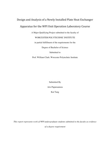
Heat ExchangerCollege of Technical7 OTHER HEAT TRANSFER APPLICATIONS7.1 JACKETED PANSIn a jacketed pan, the liquid to be heated is contained in a vessel, which mayalso be provided with an agitator to keep the liquid on the move across the heattransfer surface, as shown in Fig.3(a).The source of heat is commonly steam condensing in the vessel jacket. Practicalconsiderations of importance are:1. There is the minimum of air with the steam in the jacket.2. The steam is not superheated as part of the surface must then be used as a desuperheater over which low gas heat-transfer coefficients apply rather than highcondensing coefficients.3. Steam trapping to remove condensate and air is adequate.Some overall heat transfer coefficients are shown in Table 3. Save for boilingwater, which agitates itself, mechanical agitation is assumed. Where there is noagitation, coefficients may be halved.Table(3) Some Overall Heat Transfer Coefficients In Jacketed PansCondensing fluidHeated fluidPan materialU (J/m2 s C)SteamThin liquidCast-iron1800SteamThick liquidCast-iron900SteamPasteStainless steel300SteamWater, boilingCopper18007.2 HEATING COILS IMMERSED IN LIQUIDSIn some processes, quick heating is required in the pan, a helical coil may befitted inside the pan and steam admitted to the coil as shown in Fig.3(b). This can givegreater heat transfer rates than jacketed pans, because there can be a greater heattransfer surface and also the heat transfer coefficients are higher for coils than for thepan walls.SteamCondensate(a) Jacketed pans(b) Heating CoilFig.(8) Heat exchange equipmentMr. Amjed Ahmed21
Heat ExchangerCollege of TechnicalExample (3)Milk is flowing into a pipe cooler and passes through a tube of 2.5 cm internaldiameter at a rate of 0.4 kg/s. Its initial temperature is 49 C and it is wished to cool itto 18 C using a stirred bath of constant 10 C water round the pipe. What length ofpipe would be required? Assume an overall coefficient of heat transfer from the bathto the milk of 900 J/m2s C, and that the specific heat of milk is 3890 J/kg C.SolutionAlsoThereforebutNowq m Cp (T1 -T2)q 3890 x 0.4 x (49 - 18) 48240 J/sq UA Tm Tm [(49 - 10) - (18 10)] / ln[(49 -10)1(18 - 10)] Tm 19.6 C.48,240 900 x A x l9.6A 2.73 m2A πDLD 0.025 m.L 2.73/(π x 0.025) 34.8 mExample (4)Steam required to heat soup in jacketed pan Estimate the steam requirement asyou start to heat 50 kg of soup in a jacketed pan, if the initial temperature of the soupis 18 C and the steam used is at 100 kPa gauge. The pan has a heating surface of 1 m2and the overall heat transfer coefficient is assumed to be 300 J/m2s C.SolutionFrom steam tables, saturation temperature of steam at 100 kPa gauge 120 Cand latent heat λ 2202 kJ/kg.q UA T 300 x 1 x (120 - 18) 3.06 x 10⁴ J/sTherefore amount of steam q/λ (3.06 x 10⁴)/(2.202 x 106) 1.4 x 10⁻² kg/s 1.4 x 10-2 x 3.6 x 103 50 kg/h.Mr. Amjed Ahmed22
Heat ExchangerCollege of Technical7.3 SCRAPED SURFACE HEAT EXCHANGERSThe processing industry particularly for products of higher viscosity, consists ofa jacketed cylinder with an internal cylinder concentric to the first and fitted withscraper blades, as illustrated in Fig.(9). The blades rotate, causing the fluid to flowthrough the annular space between the cylinders with the outer heat transfer surfaceconstantly scraped. Coefficients of heat transfer vary with speeds of rotation but theyare of the order of 900-4000 J/m2s C. These machines are used in the freezing of icecream and in the cooling of fats during margarine manufacture.Fig.(9) Heat exchange equipment7.4 PLATE HEAT EXCHANGERSA popular heat exchanger for fluids of low viscosity, is the plate heat exchanger,where heating and cooling fluids flow through alternate tortuous passages betweenvertical plates as illustrated in Fig.(10). The plates are clamped together, separated byspacing gaskets, and the heating and cooling fluids are arranged so that they flowbetween alternate plates. Suitable gaskets and channels control the flow and allowparallel or counter current flow in any desired number of passes. A substantialadvantage of this type of heat exchanger is that it offers a large transfer surface that isreadily accessible for cleaning. The banks of plates are arranged so that they may betaken apart easily. Overall heat transfer coefficients are of the order of 2400-6000J/m2s C.Mr. Amjed Ahmed23
Heat ExchangerCollege of TechnicalFig.(10) Plate Heat exchangeMr. Amjed Ahmed24
Heat Exchanger DesignCollege Of Technical8 A DESIGN METHODOLOGY1. Heat Exchanger Sizing Choose a typical value for U based on the type ofservice, then determined the outlet temperatures based on the performancespecifications (number of tube, baffle spacing, etc) and the energy balance Qalso calculate heat transfer area from Q UAF Tlm.2. Heat Exchanger Rating is the computational process in which the inlet flowrate and temperatures, the fluid properties and the heat exchanger parameter aretaken as input. And the outlet temperatures and thermal duty Q (if the heatexchanger length is specified) on the required length is calculated as output elsepressure drop of each stream. (U and A are known)3. Heat Exchanger Design Is the process that determine the heat exchangerspecifications such as (length and diameter of tube, shell thickness, spacing andcut baffle.) Determine heat transfer area based on sizing calculation Determine number of tube and pass Check the velocity if below acceptable range, choose suitable number of pass. Calculate overall heat transfer coefficient and estimate the fouling resistance. Check Uassume -Ucalculate 0.001 Check the pressure drop for shell and tube sides , then determine the pumpingpower requirements for shell and tubes sides.1. Kern MethodKern Method is used to estimate the size of the heat exchanger for a givenspecification (Sizing Method), its restricted to a fixed baffecut (25%) andcannet adequately account for baffle-shell and tube-to-baffle leakagesInput (know)TciThiTcomhmcOutput (unknown)ThoQdido2. Bell Delaware's MethodIt's a rating analysis and give more satisfactory predications of the heat transfercoefficient and pressure drop than Kern Method, and it is takes into account theeffects of leakage and passing.Data of Kern Method Æ Data of Bell MethodMr. Amjed Ahmed25
Heat Exchanger DesignCollege Of Technical3. NTU MethodIt the heat duty is not known because only the inlet temperatures are given whilethe outlet temperatures are not. On the other hand the heat exchanger length is fixedand the outlet temperatures and pressure drops are to be calculated.Input (know)TciThiLmhmcOutput (unknown)ThoTcodido Ptubes PshellQ4. F-MethodWhen all of the terminal temperatures are known, than;Q UAF TlmMr. Amjed Ahmed26
Heat Exchanger DesignCollege Of Technical9. HEAT EXCHANGER DESIGN BY KERN METHODStartT1, T2, t1, Cph , Cpc . 1q mCp(Tin -Tout)orq mλCalculate: t2 from Energy Balance . 2 T2Calculate Tlm ( T2 T1 ) / ln() T1Choose Shell and Tube Passes . 3 .4From Chart estimate: S,R Æ CorrectionFactorSelectionAnother TypeSelect the type of flowCo-current ,Counter-current & Cross-flow . 5Estimate No. of Bundle PassNoF 0.852YesEstimate: UAssume from Table(12.1)6Calculate: A q/UAssume F T .lmA 20 ft220 A 500 ft2A 500 ft2Select Coil TypeSelect Double Pipe H.E. TypeSelect Shell & Tube H.E. Type3 . 7Selection Tube Diameter(di, do) 3/8", .1/2", 1/4"8Selection Tube Length (L) 8,10, 12, 16,20 ftAo πdoLNo. of Tubes Np Aoπ/DL or N . .p A/Ao9Selection another10Velocity fluid inside Tube V .tdi, doVt 2 m/s1Mr. Amjed Ahmed27
Heat Exchanger DesignCollege Of Technical1Selection tubes arrangement . . 11Triangular or Square Pitch . 12Shell Diameter Ds 8" 120" Baffle type & Space .lB13ho, hiU calculate 2 . 141 r 1r r .r 115 R fo o ln o o R fi o hok ri ri ri hiUassume UcalculateNo U assume –U calculate 0.05 . 16Yes P Tube3No . 17 Ptube 10 PsiYesPumping Power of Tube .(PPtube)18 Pshell3No . 19 Pshell 3 7.3 PsiYesPumping Power of Shell .(PPshell)20 .21Number of baffles Nb (L/lB)-1EndMr. Amjed Ahmed28
Heat Exchanger DesignCollege Of TechnicalStep 7. Choose tube type di and doAssuming tube length (L) (6, 8, 12, 16) ftAo πdoLNumber of tube Nt A/AoStep 12. Calculate the shell diameter DsKa.πDO2 N t ( PR) 2Ds 0.637CTwhere K is the Tube layout constantK 1for 90o and 45oK 0.87for 30o and 60oCT is the tube count constantCT 0.93one tube passCT 0.90Two tube passCT 0.85Three tube passPR is the tube Pitch ratio Pt/doPt is the tube Pitch[]Fig(13) Tube patternsBundle Diameter DsDs Db ClearanceDb do(Nt/K1)(1/n1)Where K1 and n1 are constant from Table 12.4b.Mr. Amjed Ahmed29
Heat Exchanger DesignCollege Of Technicaland clearance between bundle and the shell estimate from fig. (12.10)Step 13. Baffle type & Space lBlB Ds5orl B (0.3 0.5) DsMr. Amjed Ahmed30
Heat Exchanger DesignCollege Of TechnicalStep 14. Calculate heat transfer coefficient for inside tube hi µhidiNu j h Re Pr 0.33 Kf µw 0.34jh : heat transfer factor from fig.(12.23)Kf Thermal conductivity of the tube side fluidµw : Viscosity of the fluid at wall temperature TwT T 1 T TTw ci co hi ho 2 22 Mr. Amjed Ahmed31
Heat Exchanger DesignCollege Of TechnicalStep 14. Calculate heat transfer coefficient for outside tube hoho 0.36k h 0.55 1/ 3Re shell PrDeWhere De is the equivalent diameter1.27 22( Pt 0.785d o )do1.10 22De ( Pt 0.917 d o )domDRe Shell h eAs µ hDe for square Pitchfor Triangular PitchAs is the shell cross flow areaAs ( Pt d o ) DslBPtStep 17. Calculate tube side pressure drop 4 f i LN p Vc2 Ptube 4N p ρc2 di fi (1.58 ln(Retube ) 3.28) 2Step 18. The pumping power (PPt) for tube sidePPt mc Ptρ cη pWhere ηp is the pump efficiencyη p 0.8Mr. Amjed Ahmed32
Heat Exchanger DesignCollege Of TechnicalStep 19. Calculate shell side pressure drop Pshell2 Ds L ρV µ 8 jf de l B 2 µ w 0.14Where jf is the fraction factor from fig.(12.30)Step 20. The pumping power (PPshell) for shell sidePPshell mh Pshellρ hη pStep 21. Calculate the number of bafflesNb Mr. Amjed AhmedL 1lB33
Heat Exchanger College of Technical Mr. Amjed Ahmed 13 EXAMPLE 1 In a counter flow heat exchanger, water is being chilled by a sodium chloride brine. If the rate of flow of