Transcription
No. 26, Spring 2014EESy SolutionsEngineering Equation Solver NewsletterInside this issue:Welcome1The Compact Heat Exchanger1Organization3Heat Exchanger Example4Air-Side Calculations5Tube-Side Calculations7Fouling8Heat Exchanger Calculations9Plotting in Dual Units10Additional Changes to EES12WelcomeThis is the 26th issue of EESy Solutions, a newsletter thatprovides news, tips, and other updates to users of the Engineering Equation Solver software. This issue is dedicated tothe use of EES to solve Heat Exchanger problems.EES has been a commercial software for more than twodecades. If you have missed any of the previous issues ofEESy Solutions, they can be downloaded fromwww.fchart.com.The Compact Heat Exchanger LibrarySince it was first published in 1955, the book Compact Heat Exchangers by Kays andLondon has been considered the best reference for the performance of the surfacesused in compact heat exchangers. In most applications, the gas-side (typically airside) heat transfer coefficient is quite small (usually one or more orders of magnitudeless than a liquid-side heat transfer coefficient). Therefore it is almost always necessary to enhance the gas-side surface so that it has a high “area-density”. This type ofheat exchanger is referred to as a compact heat exchanger. Some examples includefinned tubes and plate fin type heat exchangers.The Compact Heat Exchanger Library in EES arranges the data presented in CompactHeat Exchangers in a functional form in order to facilitate simulating heat exchangercores that have these common geometries.F-Chart Software http://fchart.com
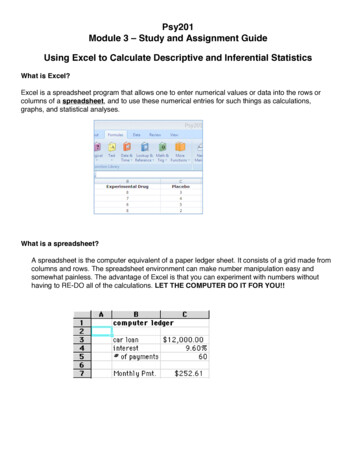
No. 26, Spring 2014Page 2The Compact Heat Exchanger LibraryExperimental data for a specific compact heat exchanger core are typically presented in terms of thedimensionless Colburn jH factor and friction factor, f, as a function of the Reynolds number, Re. TheColburn jH factor is related to the heat transfer coefficient and the friction factor is related to the pressuredrop. The plot below shows the relation for one type of heat exchanger.There are a large number of core geometriesdiscussed in the Compact Heat Exchanger bookand these data are very useful because the airflow through the finned side of a compact heatexchanger is a complex combination of internalflow in passages and external flow over tubesand other obstructions. The internal and external flow heat transfer correlations that havebeen developed for simple geometries are notapplicable for compact heat exchangers.However, it is challenging to decipher the dimensionless data presented in the CompactHeat Exchanger book in order to provide usefulengineering quantities like heat transfer coefficient and pressure drop. The Compact HeatExchanger library in EES simplifies this process.The Compact Heat Exchanger Library is accessed from the Function Information dialog byselecting the Heat Transfer radio button andthen selecting Compact HX from the drop downmenu.F-Chart Software http://fchart.com
No. 26, Spring 2014Organization of the Compact Heat Exchanger LibraryPage 3When the drop down menu associated with the Compact Heat Exchanger Library is selected, the userwill see four categories of functions labeled Non-dimensional, Geometry, Coefficient of Heat Transfer,and Pressure Drop. Under each category there is a list of different types of cores. Selecting a certaintype of core allows the user to scroll through the various specific geometries for which data are available.Non-Dimensional FunctionsNon-Dimensional functions provide the dimensionless parameters (jH and f) as a function of Reynoldsnumber; that is, they provide exactly the same information that could be obtained directly from thecharts in the Compact Heat Exchanger book.Geometry FunctionsGeometry functions provide the core-level geometric details of the core. These geometric parametersare summarized below.Coefficient of Heat Transfer FunctionsCoefficient of Heat Transfer functions require the operating conditions on the gas-side. These includethe fluid name, mass flow rate, temperature and pressure, as well as the frontal area of the heat exchanger. These functions return the air-side heat transfer coefficient for the core of interest.Pressure Drop FunctionsPressure Drop functions require the operating conditions including the fluid name, mass flow rate, inletand exit temperatures, and pressure, as well as the frontal area and length of the heat exchanger.These functions return the air-side pressure drop for the core of interest.F-Chart Software http://fchart.com
No. 26, Spring 2014Page 4Heat Exchanger ExampleA finned tube cross-flow heat exchanger is used to transfer energy from a hot ethylene-glycol/watersolution to a cold air flow. The frontal area of the heat exchanger is W 30 inch by H 24 inch andthe length of the heat exchanger is L 6 inch. The liquid flows within the tubes while the air flowsthrough across the tubes.top viewW 30 inchL 6 inchethylene-glycolsolutionairH 24 inchfront viewside viewThe finned-tube geometry is consistent with compact heat exchanger core fc tubes sCF-77558T.The ethylene-glycol solution has 1 20% concentration and enters at 80ºC with flow rate 25 gal/min. The liquid side is manifolded as shown. The air enters at 20ºC with flow rate 1920 ft3/min. Boththe air and the ethylene-glycol are near ambient pressure.The unit system is specified using the UnitSystem directive and the inputs are entered in EES. Notice that the inputs have been converted to base SI units.F-Chart Software http://fchart.com
No. 26, Spring 2014Page 5Heat Exchanger ExampleAir-Side CalculationsThe geometric details are obtained from theappropriate geometry procedure in the Compact Heat Exchanger Library. The procedureCHX geom finned tube returns the geometricdetails associated with the specific compactheat exchanger core that is being simulated.These parameters include the outer diameter ofthe tube (D o), the fin pitch (fin pitch), the hydraulic diameter on the air-side (D h), the finthickness (fin thk), the ratio of free flow tofrontal flow area (sigma), the specific surfacearea (alpha, the surface area on the air side pervolume of heat exchanger core), and the ratioof the fin surface area to total surface area(A fin\A).The most important of these parameters is thespecific surface area. In this example we willassume that the fin efficiency is 100%. The parameter A fin\A and fin thk coupled with information about the fin material would allow us to compute a fin efficiency for a more detailed analysis, butis is normally greater than 90%.In most compact heat exchangers, the gas-side (typically air-side) resistance dominates and thereforeit is often sufficient to compute the heat transfer coefficient on the gas-side for the simulation. In thisanalysis we will determine the resistance on both the air-side and fluid-side and also estimate the resistance associated with fouling on the liquid side.The air properties should be calculated at the average temperature of the air (i.e., the average of the airinlet and air exit temperatures). Because the air exit temperature is an output of the calculation, it isnecessary to assume a reasonable value. One way to do this is to enter a temporary equation thatsets the variable to a guess value (as shown in the highlighted EES code below) and proceed with thecalculations. Eventually, the guessed value will be removed and replaced with the actual calculatedvalue.F-Chart Software http://fchart.com
No. 26, Spring 2014Heat Exchanger ExamplePage 6The appropriate heat transfer coefficient procedure is selected from the Compact Heat Exchanger Library. The function CHX h finned tube requires the heat exchanger core geometry, the mass flowrate, the frontal area, the fluid, the temperature at which to compute properties, and the pressure. Thefunction returns the heat transfer coefficient on the air-side (h C)In order to compute the thermal resistance on the air-side it is necessary to determine the total air-sideheat transfer area. This is the product of the total heat exchanger volume and the specific surface area.The pressure drop on the air-side is obtained using the appropriate pressure drop procedure in theCompact Heat Exchanger Library. The CHX DELTAp finned tube procedure requires the core geometry, mass flow rate, frontal area, length in the flow direction, fluid, and inlet and outlet temperatures.Note that the entrance and exiteffects are included in the pressure drop returned by the procedure (DELTAP C). Solve andselect the variable DELTAP Cin the Solutions Window. Specify inH2O in the alternate unitsbox in order to display the valueof the pressure drop in both primary (Pa) and alternate (inH2O)units as shown.F-Chart Software http://fchart.com
No. 26, Spring 2014Heat Exchanger ExamplePage 7Tube-Side CalculationsThe ethylene-glycol solution properties should be calculated at the average temperature of the liquid.The liquid exit temperature is an output of the calculation and therefore it is again necessary to assumea reasonable value (highlighted in the EES code below) to proceed with the calculations.The tube-side geometry (i.e., the horizontal and vertical distance between tubes and the tube wall thickness) is entered based on the dimensions of the compact heat exchanger core. The number of tubes inthe vertical and horizontal directions are computed and used to compute the total length of a singlepass. The internal flow convection library is used to determine the heat transfer coefficient on the tubeside and the frictional pressure drop on the tube side. Note that the pressure input corresponds to concentration when the specified fluid is a brine.F-Chart Software http://fchart.com
No. 26, Spring 2014Heat Exchanger ExamplePage 8In addition to the frictional loss in the tubes there are minor losses associated with each 180º tube bendin the pass as well as the tube inlet and outlet. The Minor Losses library is used to determine the losscoefficient associated with these flow obstructions. The total pressure drop and tube-side thermal resistance is determined.FoulingFouling may be important in any heat exchanger. There is a library of empirical fouling factors built intothe Heat Transfer library in EES that are useful for estimating the impact of fouling. Select Fouling Factors from the drop-down menu and then scroll down to the fluid of interest (Ethylene glycol solution).The resulting fouling factor is used to estimate the fouling resistance on the tube-side. Air-side foulingis neglected in this analysis.F-Chart Software http://fchart.com
No. 26, Spring 2014Heat Exchanger ExamplePage 9Heat Exchanger CalculationsThe total thermal resistance is computed andused to determine the conductance of theheat exchanger. The capacitance rates ofthe two fluids are obtained and used to determine the number of transfer units associatedwith the device. The heat exchanger is modeled as a cross-flow heat exchanger in whichboth fluids are unmixed. The effectiveness isobtained using the effectiveness-NTU function in the Heat Transfer library. The maximum possible and actual rates of heat transfer are computed using the effectiveness.At this point the solution is complete. However, it is based on assumed values of the outlet temperatures. Update the guess values used by EES so that the most recent solution is used as the startingpoint for the iteration. Comment out the assumed values of outlet temperature.Compute the outlet temperatures using energy balances.F-Chart Software http://fchart.com
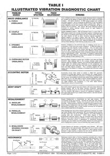
No. 26, Spring 2014Page 10Heat Exchanger ExamplePlotting in Dual UnitsThe simulation can be used to predict the performance of the heat exchanger over a range of conditions. For example, comment out the flow rate of the ethylene glycol and create a Parametric Tablethat includes the liquid flow rate and liquid outlet temperature. Vary the flow rate from 10 gpm to 30gpm and run the table.348Liquid outlet temperature (K)3473463453443433423413403393381015202530Liquid flow rate (gpm)To change the units used to create the plot, simply right-click on theT H out column and specify the alternate unit F. Click the box labeled Show values in alternate units.F-Chart Software http://fchart.com
No. 26, Spring 2014Page 11Heat Exchanger ExampleSelect New Plot Window and X-Y Plot from the Plots menu and notice that you can now select T H outin either the primary (K) or alternate (F) units as the data to be plotted.166Liquid outlet temperature ( 2530Liquid flow rate (gpm)This example is included as one of the example EES programs accessible from the Examples menuwithin EES (starting with version 9.652).F-Chart Software http://fchart.com
Some Additional Changes to EESF-Chart SoftwarePO Box 44042Madison, WI, 53744Phone/FAX: 608-274-4262Internet: http://fchart.comE-mail: info@fchart.comhttp://fchart.com Thermodynamic property data are available for the fluidsSES36, R236ea, n-Undecane, and cyclopentane Both the text color and background color of radio buttongroups and check boxes can be programmatically changedin the Diagram Window Alternate units can now be used in tables and also to create plots Tables can be saved in a Excel (.xls) file format Side-by-side bar plots can be created Text and graphics items in the Plot and Diagram Windowscan be moved using the arrow keys Deuterium properties are computed using the correlationdeveloped by Richardson et al. (2014) External functions and procedures can return warningmessages that are displayed in the Warning Window The Beep # command can be used in internal functionsand procedures to create an audible sound The Residuals and Computational Flow Windows displaythe total accumulated computational time required to solveeach equation The partial derivatives and fractional uncertainties used tocompute uncertainties can be accessed with the Uncert.ParDif and Uncert.Percent functions Unit checking has been enabled for external functions andprocedures.Instant Update ServiceEES uses a different model for updating than most other programs. Eachtime that there is a change in the EES program, either to correct a problem orto add a new feature, the version number is incremented by 0.001 and thelatest version of EES is placed on our website. Although the program hasbecome very robust and stable, there have been many new versions of EESreleased since the last EESy Solutions was distributed.Any user who has a current subscription to our Instant Update Service candownload the latest version. All new licenses of EES are provided with oneyear of Instant Update Service. The fee to continue Instant Update Serviceafter the first year is 20% of the current cost of the program per year. ContactF-Chart Software if you wish to re-subscribe to the Instant Update ServiceF-Chart Software http://fchart.com
Heat Exchanger book in order to provide useful engineering quantities like heat transfer coeffi-cient and pressure drop. The Compact Heat Exchanger library in EES simplifies this process. The Compact Heat Exchanger Library is ac-cessed from the Function Information dialog by sele