Transcription
Heat Treating Industry, Processes and EquipmentPresentation Content Heat Treating Industry and Processes Overview Heat Treating – A Video Presentation Gas Fired Metal Heat Treating Furnaces Heat Treating Atmospheres Electrical Heat Treating Systems (Furnaces) Process Heating Tools and Models for Heat Treating Emerging Gas-Fired Process Heating Equipment
Heat Treating Industry and ProcessesOverview
WHAT IS HEAT TREATING?Who Uses Heat Treating?Controlled Heatingg And Coolingg of Metal to ChangegIts Properties and Performance.Through: Change in Microstructure Change in Chemistry or CompositionCommonlyy HeatTreated MetalsTemperatureSteel MillsIron and Steel FoundriesMetal FabricationMachinery andElectrical/Electronic EquipmentTransportation EquipmentCCommerciali l HeatH t TreatingTtiSteel Service Centers3733985051To improve Toughness To increase HardnessPrimary Producers– To increase Ductility To improve Machineability To refine Grain Structure To improve Wear Resistance Heating to the Control TemperatureHolding at Temperature (Soak)Cooling (Rapid or at Slow / ControlledRate)Melt and Casting Shops, Forging Plants,Manufacturers of Automotive Parts, Farm andEarth Moving Machinery, Machine Tools, etc.Commercial Heat Treaters–ServiceSi PProvidersidffor a VVarietyi t off HHeatt TTreatingtiProcesses for Different Parts to Manufacturers.A Few Facts about Heat Treating Steel Is the Primary Metal Being Heat Treated.More Than 80% of Heat Treating Is Done for Steel.Steel Heat Treating of Metals Represents Approximately100 BCF Gas Load Nationwide. Heat Treaters Use Natural Gas to Supply About2/3 of the Energy Used for Heat Treating(induction, vacuum & commercial atmospheres arethe main competition).competition) Current Share of Gas Decisions is about 50 / 50Between Gas & Electric.H ldi (soak)Holding( k)HeatingTimeSteel Mills: Hardening of Bars, Rods Tubes,Pipes, etc.Annealing of Plates, Sheets, Wires, etc.Captive Plants– To remove Residual StressesTypical Heat Treating Cycle Industry3313323435 & 36Why Heat Treat? Ferrous Metals Steel Cast Iron Alloys St i lStainlessSteelSt l Tool SteelNon-ferrous Metals Aluminum Copper Brass TitaniumSIC
Metal Heat TreatingTopics of Presentation What Is Metal Heat Treating? Where Is It Used? WhyWh andd HowHIt IIs DDone? What Processes & Equipment Are Used forH tTHeatTreating?ti ?
What is Heat Treating ?Controlled Heating And Cooling of Metal to ChangeIt PItsPropertiesti anddPPerformance.fThrough: Change in Microstructure Change in Chemistry or CompositionTemperatureHolding(soak)Time
A Few Heat Treating Facts Heat Treating of Metals RepresentsApproximately 100 BCF Gas Load Nationwide. Heat Treaters Use Natural Gas to Supply About2/3 of the Energy Used for Heat Treating(induction vacuum & commercial atmospheres(induction,main competition). Current Share of Gas Decisions is about 50 / 50Between Gas & Electric.
Why Use Heat Treating ?In simple TermsTerms . Soften a Part That Is Too Hard. Harden a Part That Is Not Hard Enough. Put Hard Skin on Parts That Are Soft.Soft Make Good Magnets Out of Ordinary Material. Make Selective Property Changes Within Parts.
Wh uses HWhoHeat TTreatingi ? Aircraft Industry Automobile Manufacturing Defense Sector Forging Foundry Heavy MachineryMManufacturingf t i Powder Metal Industries
Wh IIndustrialWhatdi lSSectors UUse HHeat TTreatingi ?SICIndustry33133234Steel MillsIron and Steel FoundriesMetal FabricationM hiMachineryanddElectrical/Electronic EquipmentTransportation EquipmentCommercial Heat TreatingSteel Service Centers35 & 363733985051
Types of Heat Treaters Commercial Heat Treaters– Heat Treating of Parts As “Job-shop”.– Reported Under SIC Code 3398.– Approx. 10% of All Heat Treating Production Is by Commercial HeatTreaters.– Usually There Are 4 to 5 Captive Heat Treaters for Each CommercialHeat Treater Shop. Captive Heat Treaters– Usually a Part of Large Manufacturing Business.– TheyThe UsuallyUs all ProduceP od ce “Products”“P od cts” RatheRather Than PaParts.ts– Captive Heat Treating Is Scattered Through All Manufacturing SICCodes (DEO has over 100 individual SIC’s for Heat Treaters).
Commonly Heat Treated Metals Ferrous Metals––––– SteelCast IronAlloysStainless SteelTool SteelNon-ferrous l Is the Primary Metal Being Heat Treated.More Than 80% of Heat Treating Is Done for Steel
Heat Treating Processes
Steps in Heat Treating Operation Loading Cleaning Pre-wash with coalescer De-phosphate system Spray rinse Tempering Surface coating Unloading Heating Preheatingg Heating Soak & diffusion Pre-cooling Quenching (Cooling) Post-wash
Commonly Used Equipmentfor Heat Treating Operations Metal Cleaning (Wash-Rinse) EquipmentGas fired furnaces–––– Direct fired using burners fired directly into a furnaceIndirect fired furnaces: radiant tube, muffle, retort etc.Molten salt (or lead) bathFluidized bedElectrically heated Furnaces– Induction heating– Electrical resistance heating– Other ((i.e. Laser,, electron-beam etc.)) Quench or cooling equipmentMaterial handling systemTestingg anda d qualityqua y controlo o laboratoryabo a o y equipmentqu p
Gas Fired Metal Heat Treating Furnaces
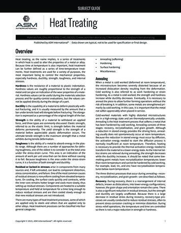
Electrically Heated Equipment for Metal HeatingElectric Atmosphere FurnaceVacuum FurnaceInduction Equipment
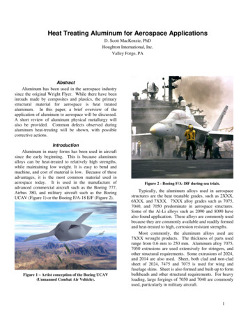
Types of Heat Treating FurnacesBox4560InductionCarbottom100150Bell, Hood, tipupp p150Vertical Pit60Vacuum13425Box1007700Salt BathLead pot (cont.)Rolelr hearthBarre-rollerCont. striplineCont. induction200Conveyor4395Car Bottom6000PusherPusherFluidized bedSalt-bath3195Conveyor4890Bell hood,Bell,hood tip-up503305551304765Vertical PitRotary hearth, shaker hearthPlasmaInductionLaser2510VacuumElectric beamFlame heads
Heat TreatingProcessing EquipmentGas Fired Furnaces
Heat treating furnaces can be Batch type or continuousThe furnaces are heated by: Direct fired gas burners, Radiant tubes or Electric heatingelementsMore than 60% of the total energy used for heat treating is used for heating the loadComponents of of a typical heat treating line Loading station Parts washer and dryer Heat treating furnace (carburizer,h d i furnace,hardeningfvacuum furnacefetc.) Atmosphere supply (generator or commercial) Quench Washer and dryer Tempering furnace Unloading Quality control – inspectionCommonly used furnaces Integral Quench Furnace (i.e. AllCase Furnace) Types of Heat TreatingVacuumAtmosphericpat ambient Operated(atmosphere) pressure. Operatedpat vacuum orsub-atmospheric pressure. Load is heated and cooled inpresence of air or specialgases (process atmospheres), May involve high pressuregas cooling using specialgases.in liquid baths or in a fluidizedbed. Includes ion or plasmaprocessing equipment.Major Components of a FurnaceProcess AtmosphereRoller hearth, shaker hearth, pusher, mesh-belt,Retort etc.Vacuum furnaceFluidized Bed FurnaceCar Bottom FurnaceSalt Bath FurnacePit furnaceFurnacesExhaust GasesHeat ContainmentHeatGenerationEnergy Source(fuel, electricity, terialHandling
Heat Treating FurnacesTwo Primary Types Atmospheric– Operated at ambient (atmosphere) pressure.– Load is heated and cooled in presence of air orspecial gases (process atmospheres), in liquidbaths or in a fluidized bed. Vacuum– Operated at vacuum or sub-atmospheric pressure.– MMay involveil highhi h pressure gas coolingli usingispecial gases.– Includes ion or plasma processing equipment.
Heatea SouSourcece foro Gas Fireded Furnacesu aces Direct Fired Burners * Radiant Tubes * Muffle or Retort Heated byOutside Burners/ElectricalElements Hot Oil or Steam HeatingMuffleBurnersDirect fired muffle furnace* These could be directly exposed to the workor can be outside a muffler a retort.
Typical Combustion SystemDirect Fired FurnacesMulti-zone, Multi-Burner SystemIndirect Fired FurnaceRadiant Tube Firing withpfor PreheatinggRecuperatorCombustion Air
Two Major Issues Facing Natural Gas HeatingNOx Emissions and Efficiency Low NOx burners areavailable for all temperatureranges.Low NOxHigh Velocity Use of recuperators,regenerative burnersbcanincrease efficiency of gas useby 25% to 40%. Proper combustion controland selection of rightburners.Regenerative Burners
Gas Fired Metal Heat Treating Furnaces
Integral Quench (IQ) Furnace “Work-horse”Work horse of Heat TreatingIndustry A Batch Furnace for Hardening &Carburizing Includes a Quench and CoolingChamber Can Be Single Chamber (In-out)(In out) orTwo Chamber Load From 800#s to 6,000#s Operating Temperature – Usually up to1,800 F
Integral Quench (IQ) Furnace Radiant Tubes (Gas Fired)or Electrically Heated. May or May Not Have aMuffle to Separate Load andRadiant Tubes. Process Atmosphere: EndoGas, Equivalent CarburizingGas Mixture or NeutralAtmosphere.Atmosphere Circulating Fan to Assist inConvection Heat Transfer.
Tempering or Draw Furnace Batch Furnace for Pre-heating,TTemperingi (after( fquench),h)Stress-relieving andAnnealing. OOperatingti TemperatureTtRange: 350 F to 1,400 F. May Include Cooling SystemUsing Air to Water HeatExchanger to AccelerateCooling. Direct Fired With Flue GasAtmosphere (some VacuumTemper Furnaces used).
Tempering or Draw Furnace Convection Heating Using aRecirculating Fan. Load Capacity; 1,000# to3,500#. IncludesI l d a PlenumPlforf GasGDistribution and TemperatureUniformity.y
Quench TankQ Directly Connected or Integral to aFurnace.Furnace The Liquid Can Be Water, Quench Oilor Polymer. Requires Heating and Cooling Systemto Maintain the Controlled QuenchTemperature. Major Concern for Oil Quench: Fire,For All Other: Spill. Extremely Critical for Quality of theParts Produced.
Parts Washer(Batch System)y Used to Clean Parts (Remove Dirt,Machining Oil, Metal Chips, etc.). May Use Chemicals - Detergents . Includes Several Steps ofWashing, Rinsing, Drying, etc. Requires Heating System Insideandd Outsided (for(f Liquids)d ) thehWasher. May Use Vacuum De-oiling.g Requires Extensive LiquidHandling System to AssureCompliance with EPA Regulations.
A Typical Heat Treating LineFront Section with Pre-wash and Furnace
Heat Treating LineBack Section with Tempering and Post-wash
Nonferrous Heat Treating FurnacesTypes of Furnaces Coil/foilC il/f il AnnealingAli FurnacesF Rod/wire Annealing Furnaces Logg Homogenizinggg Furnaces Ingot Preheating Furnaces Aging Furnaces Indirect Heating(Radiant Tubes or Electrical Resistance) TemperaturepRangeg 350 F to 1150 F Atmosphere With Dew Point Control May Includes Water Quench orControlled Coolingg
Process Atmospheres forHeat Treating
What is a Process (heat Treating) Atmosphere?A Mixture of Gases (CO, H2, CO2, H2O and N2) That Protects the Load or Reacts with the Load During Heat TreatingWhy Use protective Atmospheres? To Prevent Oxidation, Loss of Carbon (Decarburizing),and Avoid Corrosion.–Most Gases Containing Oxygen (i.e. Air, WaterVapor [H2O], Carbon Dioxide [CO2] React WithIron, Carbon and Other Elements Present inSteel.–Reactivity Depends on Temperature and Mixtureof Gases in Contact With Steel.Source of heat Treating Atmospheres Natural Gas (Hydrocarbon) - Air Reaction Natural Gas - Steam Reaction Ammonia Dissociation or Ammonia-airReactionOrO Mixture of Commercial Gases(N2, H2 and Hydrocarbons)Types of Heat Treating Process Atmospheres Protective–To Protect Metal Parts From Oxidation or Loss ofCarbon and Other Elements From the MetalSurfaces.Reactive–T Add Non-metallicToNt lli (I.E.,(I E Carbon,C bOxygen,ONitrogen) or Metallic (I.E., Chromium, Boron,Vanadium) Elements to the Base Metal.Purging–To Remove Air or Flammable Gases FromFurnacesor Vessels.VlCommonly Used of heat Treating Atmospheres Rich and Lean Endothermic (DX) Gas Rich and Lean Exothermic (RX) Gas(These can have low or high dew point) Dissociated Ammonia Hydrogen – Nitrogen Mixture Natural Gas (Hydrocarbon) - Air Reaction Natural Gas - Steam Reaction Mixture of Commercial Gases(N2, H2 and Hydrocarbons)
Why Use Protective Atmospheres? TTo PreventPtOOxidation,id tiLossLoff CarbonC b (Decarburizing),(Db i i )and Avoid Corrosion.– Most Gases Containingg Oxygenyg (i.e.(Air,, Water Vaporp[H2O], Carbon Dioxide [CO2] React With Iron, Carbonand Other Elements Present in Steel and Other Metals.– Reactivity Depends on Temperature and Mixture ofGases in Contact With Steel. To Avoid and Eliminate Formation of Flammable orE l i MixturesExplosiveMi t
Types of Process Atmospheres Protective– To Protect Metal Parts From Oxidation or Loss of Carbonand Other Elements From the Metal Surfaces. Reactive– To Add Non-metallic (i.e., Carbon, Oxygen, Nitrogen) orMetallic (i.e., Chromium, Boron, Vanadium) Elements tothe Base Metal. Purging– To Remove Air or Flammable Gases From Furnacesor Vessels.
Importance of Protective Atmospheresin Heat Treating Proper composition and concentration in a furnace is requiredto give the required surface properties for the heat treatedparts. Loss of atmosphere “control” can result in unacceptable partsand result in major economic penalty - it can cost a lot! Atmospheres contain potentially dangerous (explosive, lifethreatening) gases and must be treated with “respect”. New advances in measurement and control of atmospheres inheat treating allow precise control of atmospheres to producequality parts.
Commonly Used Atmospheres in Heat TreatingProtective and Purging– Endothermic gases Lean – high and lowdew point Rich - highg and lowdew point– Nitrogen– Mixture of N2 andsmall amount of COReactive– Exothermic gases– Mixture (or individual) ofgases: Hydrogen, CO,CH4 Nitrogen and otherCH4,hydrocarbons– Dissociated Ammonia(H2 N2)
Source of AtmospheresRequirement:A Mixture of Gases (CO, H2, CO2, H2O and N2) That Givethe RequiredqCompositionpfor the Processingg Atmosphere.p Natural Gas (Hydrocarbon) Air Reaction Natural Gas - Steam Reaction Ammonia Dissociation orAmmonia-air ReactionOr: Mixture of Commercial Gases(N2, H2 and Hydrocarbons)
Use of Atmospheres in a PlantRequirement:A Mixture of Gases (CO, H2, CO2, H2O and N2) That Givethe RequiredqCompositionpfor the Processingg Atmosphere.p Most plants have an in-house, centrally located,pgasg generatorsgfor different typesyp ofatmosphereatmospheres required in the plant In some cases one or more generators may bep or productionparealocated for each “shop” In many cases other gases (i.e. N2, H2, NH3)are piped from storage tanks located within theplant premisesppand distributed byy a pipingpp gsystem to furnaces. Gas flow is mixed, measured and controlled priorjin the furnace.to its injection
Electrical HeatingSystemsfor Heat Treating
Type of Electric HeatingResistance HeatingCost ComparisonElectric vs. Natural GasCent/Kwh /MM 33 9333.9337.01Induction HeatingDirect CurrentLaser HeatingElectron Beam HeatingPlasma HeatingArc HeatingBased on 90% efficiencyin distributionAdvantages Claimed By Electric System ProvidersMajor Applications of Electric Heating for Heat Treating Vacuum Heat Treating Furnaces Sintering (Powder Metal) Furnaces Plasma or Ion Nitriding, Carburizing or SurfaceCoatings Low Temperature Tempering or Draw Furnaces Liquid (Water, Quench Oils or Polymer) Heating inTanks Gas Generators (Endo Gas and AmmoniaDissociators) Salt Bath Furnaces Pit (Underground) Furnaces “100100 %”% Efficient Better Temperature Uniformity andControllability Can Be Used for Higher TemperatureProcessesHigher Operating Cost : 2 to 3 Times forHeat Treating Furnace Applications Capital and Operating Cost Heating Elements Burn-out, Short Lifeand Expensive to Replace Product Loss Danger of Elements Shorting Due toPossibilities of Metal Parts Drop Environmental, Safety and May Need Expenses for Substation,Transformer Etc. Corrosion, Soot Deposits Etc. ForApplications With Process Atmosphere Longer Furnace Length for the Same HeatInput, Particularly for Continuous Furnace Safe - No Explosion Hazards No Flue Gases to Deal With No Pollution or Emissions of NOx Etc. Lower Initial Cost for Furnace Easy to Install and Operate Can Be Easily AutomatedDi dDisadvantagest- DrawbacksDb kMajor Issues and ConcernsHealth Productivity and Quality Other factors
Electrical Heating Terms and CostCost of Electric HeatingCent/Kwh456789101112 Energygy is measured in terms of KilowattHour (Kwh). 1 Kwh 3,413 Btu/hr. Electricity production is approximately33% efficient based on energy requiredat the power plant. For an equivalent (delivered to the load)Btu basis electricity production emits 2to 5 times more NOx than the gas firedfurnaces. Actual efficiency of application of heatcould be in the range of 65% to 85%. /MM sed on 90% efficiency indistribution
Advantages Claimed By Electric System Providers “100100 %%” Efficient Better Temperature Uniformity and Controllability Can Be Used for Higher Temperature Processes Safe - No Explosion Hazards No Flue Gases to Deal With N PNoPollutionll i or EmissionsE i ioff NOx Etc.E Lower Initial Cost for Furnace Easy to Install and Operate Can Be Easily Automated
Disadvantages - Drawbacks Higher Operating Cost : 2 to 3 Times for Heat TreatingFurnace Applications Heating Elements Burn-out, Short Life and Expensive toReplace Danger of Elements Shorting Due to Possibilities ofMetal Parts Drop Ma Need EMayExpensespenses fofor SSubstation,bstation TTransformeransfo me EtcEtc. Corrosion, Soot Deposits Etc. For Applications WithProcess Atmosphere Longer Furnace Length for the Same Heat Input,Particularly for Continuous Furnace
Primary Applications ofElectric Heating for Heat Treating Vacuum Heat Treating Furnaces Sintering (Powder Metal) Furnaces Plasma or Ion Nitriding, Carburizing or Surface Coatings Low Temperature Tempering or Draw Furnaces Li id (Water,Liquid(W t QuenchQh OilsOil or Polymer)P l) HeatingH ti ini TanksT k Gas Generators (Endo Gas and Ammonia Dissociators) Salt Bath Furnaces Pit (Underground) Furnaces
Electrical Heating Systemsfor Heat Treating Resistance Electrical Heating Systems–– Electrically Heated Conventional FurnacesElectrically Heated Atmosphere FurnacesElectrically Heated Vacuum Furnace–Heating and heat treating–Plasma Nitriding–Plasma Carburizing–CVD CoatingsCCoa gsInduction Heating
Majorj Componentspof anElectrical Heating System Heating Elementsl Power Supply Power Control System Connected withth FtheFurnace TTemperaturetCControlt lSystem Water Cooling System
Electrically Heated Atmosphere FurnaceNotice: Electric heating elements connections Lack of burners, vents, airair-gasgas piping or flue gas vents or ducts
Features of anElectrically Heated Vacuum Furnace VVacuumVesselVl With WaterW t CooledC l d ShellSh ll– High Temperature Heating Elements(Graphite, Molybdenum, etc.)– Insulated Shield Between the Elementsand Water Cooled Shell Gas Circulating Fan With Water CooledHeat Exchanger and Gas AccumulatorWater Re-circulating and Cooling SystemVacuum Pumping SystemControlsMaterial Handling System
Primary Reasons for the Useof Vacuum Heat TreatingNegative:Ni Higher Capital Cost Higher Utility(Electricity) CostgOverall HigherOperating Cost Lower OverallCapacity Less FlexibilityPositive:Pii Process Repeatability Temperature Uniformity Reliability of Operations Better Operating Environment No or Low Environmental(Perceived Emission) Problems Automation - Better Applicationfor Computer Control
Induction HeatingforH TreatingHeatTi AApplicationsli i
What is Induction Heating?g Method of heating electricallyconductive objects. No contact requiredqbetweenthe object and source of heat. Heat can be applied to localizedareas or surface zones. High surface heat flux relatively short heating time.time
Applications of Inductionfor Metal Heating SpotSHHeatingi - Brazing,Soldering, Local Heating, SpotHardening. Surface Heating - SurfaceHardening, Curing, Shrink Fit ThroughThh HeatingH ti - Tempering,Forging, Annealing, ThroughHardening. Melting - Steel, Copper, Brass,Aluminum
Gas Fired Vacuum Furnaceswww.gasfiredvacuum.comPresented under Available / Emerging Technologies
Process Heating Tools and ModelsModels*These Toolswill help youProsper!Thanks forShowing UsHow!Understanding ISthe Key toObtain Results!*Content Partially Provided Through Dominion Participation in both the Energy SolutionsCenter’s Heat Treat Awareness Consortium and the DOE BestPractices Program
How to Use These Tools and Models1.Discuss the fundamental cost differences between natural gas andelectricityl t i it withith customers.tElectricEl t i costt isi usuallyll 3 tot 5 timestitheth gascost on the basis of the total BTU’s supplied to the process equipment.2.For most plants, a relatively small number of all installed processq pusuallyy consume the largestgamount of energy.gy Identifyy theequipmenttop-users and gather basic information on energy use for all majorenergy use equipment in the plant.3.For major energy using equipment, record name-plate data and analyzehow and when energy is usedused. ThenThen, estimate the efficiency of theprocess based on age of existing equipment (older is lower efficiencygenerally), actual data, referencing the charts included in these Toolsand Models or by contacting the original equipment supplier.44.The operation cost comparison for selected equipment can becompleted by entering efficiency and energy cost information in theCost Comparison Calculator Model cells OR by reading the generalresults, in certain cases, from the charts (see pg’s 4 & 5).Cost Comparisonfor Gas Comparedto Electrical HeatFactors affectingffenergy cost includel d 1)) Efficiencyffoff gas andd electricallylllheated furnaces 2) Cost of gas and electricity and 3) Number of hoursequipment is operated.
Factors affecting efficiency of gas-firedequipment1.22.3.4.Flue (exhaust) gas temperatureOxygen (or CO2) in flue gasesCombustion air temperature (to the burner)Oxygen injection or enrichment (if any) in theincoming combustion airFactors affecting efficiency of electric equipment1. Power factor2. Losses in distribution system (from meter touse)3. Water cooling of components4 Induction coil and load coupling4.
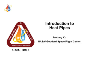
Process Heating Cost ComparisonGas Cost Equivalent for Electric Process*1: If Efficiency is different than the three shownhere use the Cost Comparison CalculatorGas Cost vs. Electric Cost(Electric Heating "Efficiency" at 6060, 75 or 85%) *1Gas Costt /MM Btuu35.0030 0030.00Electrical Equipm ent Efficiency - 60%25.0075%20.0015 ty Cost Cents/kW9.010.0
Process Heating Cost ComparisonElectric Cost Equivalent for Gas Process*1: If Efficiency is different than the three shownuse the Cost Comparison CalculatorElectric Cost vs. Gas Cost(Gas EquipEquip. Heating Efficiency at 40,40 60 and 80%) *11Electricity CCost Cents/kWW8.07.0Gas Equipmentq pEfficiencyy - 00Gas Cost /Million Btu10.0011.00
Cost Comparison CalculatorFind Equivalent Electric RateGas Equipment EfficiencyElectric Heating EfficiencyGas Cost60%85% 5.50% - Percent% - Percentper million Btu (Mcf)Gas equipment provides cost savingswhen electric power cost is equal to(or higher) than this power rate2.7Cents/kWNote: TNTo EEnter EffiEfficiencyi& Energy Cost Data,“Double-Click” on theGreen portion of the tablecell. Then “Click” againin the cell and makedesired entry. Finally,“Click” once outside thecell to view results. DoNOT Enter Informationin Blue Cells.Find Comparable Gas RateElectrical Equipmentq pEfficiencyyGas Equipment EfficiencyElectricity CostGas equipment provides cost savingswhen gas cost is equal to (or below)this gas cost85%60%4.59.31% - Percent% - PercentCents/kwh /MM Btu (Mcf)
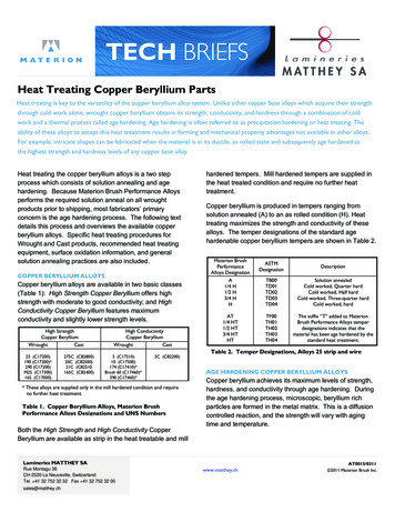
Avaialbile Heat in Gas-Fired SystemsAssumption; 10% Excess air, or 2% O2 in flue gasesAvailable heat is the m axim um possible "efficiency".Generally, efficiency is 75% to 90% of the avaialble heatshown on this graph.Perccent Available Heat (%)908070605040306008001,0001,2001,4001,600E hExhaustt FlueFlGasGTemperatureTt(Deg.(DF)1,8002,000
Typical Electric System Available Heat forProcess Efficiency FactorsElectrically HeatedSystems has ALL the9 Vacuum – 60%same losses as gasgas-firedfired9 InductionI d ti UUnderd 22,000000 F – 65%systems except Flue Gas9 Induction Over 2,000 F – 40%Losses. Line losses from9 SCR - 75%metering to application9 ResistanceR itElElementst – 85%also exist.9 All Other - 75% If Unsure Of ActualNote: ContactCyour equipmentiEffi iEfficiencyuse 75% inisupplier to verify actualthe Cost ComparisonfactorsCalculator.
How to Use Two Models to Determine Base & Modified Energy Use1.In the Base Case model, enter measured data in Green Cells thatpertaint i tot ththe currentt combustionb ti systemtoperatingti condition.ditiIf ddatat iisnot known, a portable combustion flue gas analyzer and a thermocoupleis needed to obtain this the Excess O2 and Flue Gas Temp. information.2.For most non-recuperatednon recuperated combustion systems, the flue gas temperatureexiting the process will average between 100 and 200 F higher than theprocess temperature. Also, the flue gas oxygen content for many oldercombustion systems will range from 3 to 9%. Additionally, thecombustion air temperature will correspond to the ambient conditionsnear the equipment. Unless you know, use 100 F.3.For the Modified Case, recuperative combustion systems can provide arange of preheated combustion air temperatures. Most systems willpreheat air to at least 400400–600600 FF. Some will provide significantly more(as high as 200 F below operating temperature). If unsure, use 500 Fand assist the customer in confirming the possible temperature with aqualified burner company or equipment supplier representative.Cost Comparisonfor Gas Comparedto Electrical HeatFactors affecting energy cost include 1) Efficiency of gas and electricallyheated furnaces 2) Cost of gas and electricity and 3) Number of hoursequipment is operated.
Process Heat Cost ModelBaseBaseCaseFurnace FlueGasTTemperaturetOxygen in FlueGasesExcess AirDeg. F.%%Deg. F.% of grossHeating Value1 6001,600616.138 338.310043 5043.50Gas equipment provides savings when gascost is equal to (or below) this gas costPower Cost (Cents/kWh), enter in 0.045formatInput Data in Green Cells 30.310.045CombustionAirAvailable HeatTTemperaturetNote:NtAfter Entering GasCombustion Data, Inputthe Current Power Costto Determine the GasCost Point that ProvidesSavingsView Result
Process Heat Cost ModelM difi dModifiedModifiedCaseCombustionAirAvailable HeatTemperatureFurnace Flue GasTemperaturepOxygen in FlueGasesExcess AirDeg. F.%%Deg. F.% of grossHeating Value1 4001,400212.110 210.250066 1766.17Note:Gas equipment provides savings when gas costis equal to (or below) this gas costPower Cost (Cents/kWh)Input Data in Green Cells 19.930.045To Enter Data, “DoubleClick” on the Greenportion of the table cell.Then “Click” again inthe cell until the curserappears and makedesired entry. Finally,“Click” once outside thecell to view results.View Result
EEmergingi GasGasG -FiredFi d ProcessPHeatingH i EquipmentE i Gas Vacuumwww.gasfiredvacuum.com Fuel Based Nitrogenwww industrialcenter orgwww.industrialcenter.org Flame Treating Systemswww.flamesys@gte.net Composite Radiant TubesT beswww.griweb.gastechnology.orgwww.flox.comwww shunk-inexwww.shunkinex.comcom Fluidized Bedwww.rapidheattreat.com(available soon)
Gas-FiredGasFired Vacuum Furnaces (GFVF) (GFVF) are a credible and low maintenancealternative to electric vacuum furnaces.furnaces GFVF utilize innovate burner designs to treatmore parts at lower costs while meeting orexceeding temperature uniformity and surfacequality standards.standards There are many applications for thiscontinually advancing technology.A li tiApplicationsHeat treating to 1,850 F (higher temperatures available soon) includingNormalizing, Annealing, Stress Relieving and others Who to contact?Surface Combustion, Thermotech and AFC-Holcroft offer GFVF’s. Visit the“Resource Center” section of www.gasfiredvacuum.com to contact them.Web site: www.gasfiredvacuum.com
Fuel-Based Nitrogen (FBN)AAtmospherehGeneratorGSteamNOx and O2Reduction Produces BOTH high-quality processatmosphere and steam. Natural gas used forboiler and atmosphere use is combined. NOx reductions measured at over 90% comparedto standard systems. Reduces operating cost substantially.substantially Recentinstallations report annual natural gas,maintenance and labor savings exceed 250,000. 500,000 annual saving have rCompressorFuelPurificationOutputInput RaitoControl StorageTankA li tiApplicationsFerrous and NonFerrous Annealing, Sintering, Brazing andGalvanizing of Rod / Wire, Sheet, Tube and other parts / shapes Who to contact?Energy Resource Control Corp., Cleveland, OhioPhone: 440.734.2560 Fax: 440.779.9184Web site: www.industrialcenter.org (click on “TechnologyTechnology TourTour” button)
Flame Treating Systems, Inc. (FTSI) Natural gas FTSI units are efficient, economicaland easy to install. Versatile designs withpackaged and custom-designed options. PLCcontrolled for repeatable and reliable operation. FTSI reduces energy costs and can be installedin low and high temperature applications. Competes with induction at significantly lowercapital cost.A li tiApplicationsHardening surfaces of parts, through heating prior to forming or forging, andpreheating. Metals, plastics, and other process applications exist Who to contact?Flame Treating Systems, Inc. Durham, NC1.800.435.5312Web site: www.flamesys.com
Composite Radiant Tubes (CRT) Available since the late-1980’s, CRT’s increaseheat release, allow maximum processt
- Approx. 10% of All Heat Treating Production Is by Commercial HeatApprox. 10% of All Heat Treating Production Is by Commercial Heat Treaters. - Usually There Are 4 to 5 Captive Heat Treaters for Each Commercial Heat Treater Shop. Captive Heat Treaters - Usually a Part of Large Manufacturing Business.