Transcription
Numerical analysis of forming sheet panels with stiffening ribsXIII International Conference on Computational Plasticity. Fundamentals and ApplicationsCOMPLAS XIIIE. Oñate, D.R.J. Owen, D. Peric and M. Chiumenti (Eds)NUMERICAL ANALYSIS OF FORMING SHEET PANELS WITHSTIFFENING RIBSJ.ADAMUS AND P. LACKICzestochowa University of Technology (CUT)Dabrowskiego 69, 42-201 Czestochowa, Polande-mail: janina.adamus@gmail.com, http://www.pcz.pl/Key words: Numerical Simulation, Sheet-metal Forming, Titanium Sheet, Stiffening Rib.Abstract. The transport industry, especially aviation, pays special attention to vehicle weightbecause lower weight means lower fuel consumption and in turn lower environmentalpollution. Not only light metals like aluminium and magnesium alloys or titanium and itsalloys are of interest in the transport industry but also new production technologies are takeninto consideration as factors decreasing structure weight. Sheet metal forming offers light andstrong components, therefore monolithic e.g. casting components are often replaced by drawnparts made of sheet metals. Forming large panels of thin sheets, especially hard-to-deformsheets with a high susceptibility to spring back, is a huge challenge. Forming both aluminiumand titanium alloy sheets as well as nickel based steel sheets, which are the main structuralmaterials in aviation, is difficult. Titanium, particularly titanium alloys, in comparison to steeland aluminium has a much more beneficial specific strength (strength-to-weight ratio)therefore it is used where high mechanical strength and low weight of the construction areespecially essential. However, there are many technological problems, such as: poordrawability, high spring back and low tribological properties that have to be overcome in coldsheet-titanium forming. In the paper, numerical analysis of forming a part of a large sheetpanel will be presented. The numerical simulation will be performed using the PamStampprogram specially dedicated to sheet-metal forming. The program is based on the finiteelement method (FEM). The stress and strain distributions in the analysed part will bepresented. The effect of the blank-holder force and frictional coefficient on the formingprocess will be studied. The quality of the obtained drawn part will be assessed based on thecorrectness of its shape and dimensions with reference ones, as well as on the thinning of thedrawn part material.1INTRODUCTIONThe transport industry, especially aviation needs strong and light materials for theirconstruction because lighter aircraft means lower fuel consumption, and consequently lowerlevels of exhaust emissions and environmental pollution [1-4]. When selecting materials foraircraft structural parts, specific gravity in particular is taken into account, and in this respectmagnesium and aluminium alloys as well as titanium materials are the most favourable.However, considering material strength, both aluminium and magnesium alloys are inferiorto titanium alloys, which have the highest specific strength among all structural materials, i.e.204
J. Adamus and P. Lackithe highest strength-to-density ratio up to 600oC. Above this temperature only steel-nickelalloys can work, unfortunately their specific weight is nearly two times higher than titaniumalloys. Therefore, in order to reduce construction weight there is a tendency to replacemassive cast parts with lighter ones made of sheet-metals. Among many producingtechnologies, such as casting, machining, metal forming or powder metallurgy, sheet-metalforming seems to be the most appropriate concerning the strength and lightness of thin-wallproducts [5-7]. Sheet-metal forming processes give the possibility to manufacture drawn partsin different sizes - from small to huge components, with different geometry - from simple tocomplex geometry, and very often near-net-shape parts, which do not need extra machining.A further decrease in construction weight is possible using tailor welded blank (TWB)technology [8-12] as well as honeycomb structures [13,14] but the development of thesetechnologies would not be possible if not for the progress in welding technologies, includingelectron and laser beam welding [15-20] as well as friction stir welding [21,22]. Modernwelding technologies allow not only for the creation of new aviation designs but also themodification of existing ones. Because the design criteria, especially in aviation arecomplicated and require expertise and experience, all improvements require computationalsupport in modelling and simulation of both material and process design [23-26].Apart from theoretical problems, the implementation of new advanced technologies as wellas high strength materials requires solving numerous technological problems. Sheets made ofsuch materials, e.g. titanium alloy, are characterised by low drawability at ambienttemperature and high spring back. In order to improve their drawability and eliminate springback phenomena, forming at a higher temperature is usually applied [27,28]. However, itinvolves, especially during titanium forming, the use of protective atmosphere or vacuum toavoid gas absorption and hence material embrittlement.Titanium in addition to favourable specific strength has good corrosion resistance to manytechnological environments and because of its high melting point (1,668 C), it is consideredas a fireproof material suitable for firewalls. Even though sheet-metal forming has beenknown for many years, forming titanium sheets still poses many problems [29-32]. Titanium,especially titanium alloy sheets have poor drawability [7,29], a tendency to fracture [33], highspringback [34,35] and unfavourable tribological properties, particularly an inclination togalling [29,36].Forming large panels like enclosures or firewalls from thin sheets is a real challenge.Generally, all panels made of sheets tend to buckle and vibrate. In order to stiffen huge panelsand reduce sheet flex, it is necessary to emboss some ribs (stiffeners), which can also be usedto create decorative elements in a product that would otherwise be cost prohibitive. Embossedstiffeners allow constructors to reduce sheet-metal thickness, which is essential concerningstructure weight reduction without decreasing its strength or rigidity. Although theseembossed stiffeners are usually shallow, it is very difficult to avoid the deformation of flatpanel areas, especially if it is made of hard-to-deform materials like titanium and in additionto a very thin sheet. Even slight panel deformation poses problems during componentassembly. Therefore, in the work springback phenomenon during forming a part of a titaniumsheet panel with embossed stiffeners is studied.205
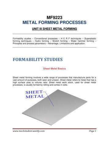
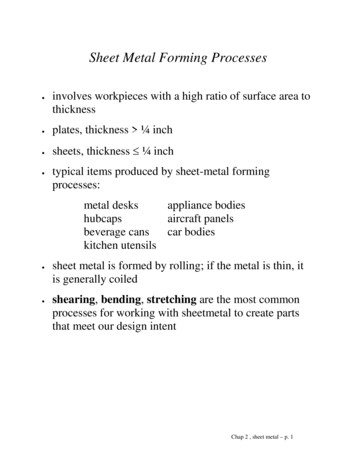
J. Adamus and P. Lacki2 GOAL AND SCOPE OF WORKThe work aims at elaborating some guidelines on how to form large thin titanium sheetpanels having enough stiffness to avoid bending or twisting and losing the original shapeduring exploitation.In order to increase the titanium panel stiffness, some embossed stiffeners, which areshown in Figure 1, were designed on the panel surface. Embossing is usually used to form apattern or design on ductile metals because of aesthetic or functional reasons. In the work thefunctional application is considered. Generally, such stiffeners should be formed bystretching, however, some part of the deformed material can be drawn from the sides of thesheet panel into a shallow depression. The clue to this process is how to ensure pure stretchforming, in which the metal sheet is completely clamped round its circumstance and the shapeis achieved at the expense of sheet thickness. Stretching the metal causes it to become thinner.embossedstiffenersFigure 1: Geometry and position of embossed stiffenersTo optimise the process parameters, such as blank-holder force and frictional conditions,a virtual embossing process was designed using PamStamp 2G v. 2011 [37], which providessolutions for sheet-metal forming processes especially in the automotive and aerospaceindustry. The system is based on the finite element method (FEM).In the work, a part of a large panel with embossed stiffeners is analysed. The panel is madeof a commercially pure Gr 2 titanium sheet with a thickness of 0.4 mm, which poses a basicdifficulty due to the low ductility and high spring-back of such a thin Gr 2 titanium sheet.The effect of the blank-holder force and frictional conditions on the stress and straindistribution in the analysed part are studied.3NUMERICAL CALCULATIONS3.1 Numerical modelThe surface model of the tool was prepared using Catia v. 5, and then the model was putinto PamStamp 2G. 4-node shell elements were used for generation mashes on both the blankand the stamping tool, which consists of a die, punch and blank-holder. Boundary conditionswere assigned to each part of the tool to specify their position in the coordinate system. All206
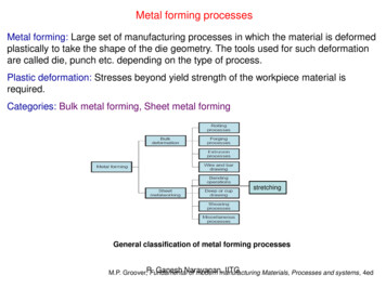
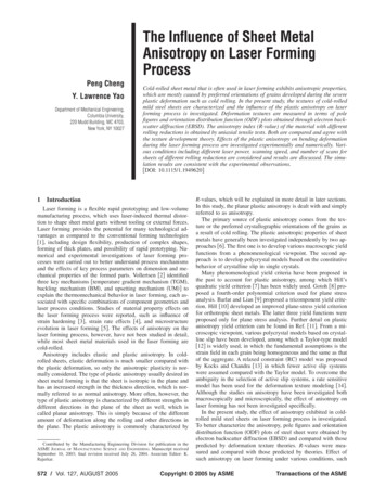
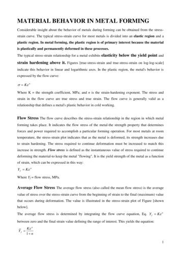
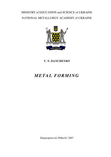
J. Adamus and P. Lackidegrees of freedom were moved away from the die while the punch and the blank-holder havethe possibility to move on the Z axis. It was possible thanks to the applied velocity vector tothe punch as well as force to the blank-holder. The blank had all degrees of freedom. Thenumerical model of the tool is shown in Figure 2 while the material data for the Gr 2 sheet,which were assumed in the calculations are given in Table 1.punchesblankholderblankdieFigure 2: Numerical model of toolTable 1: Material properties assumed in numerical calculationsMaterialGr 2Young’smodulusE [GPa]105Offset yieldpointRp0.2 [GPa]0.236Poisson’sratioν [-]0.37Densityρ [kg/m3]4,500StrengthcoefficientK [GPa]0.465Strainhardening exp.n [-]0.125The material anisotropy was described using Hill'48 yield criterion. The strain-stress curve,which is presented in Figure 3, is defined based on Hollomon’s law:σ Κ · εn(1)where: K - strength coefficient, n - strain hardening exponent.0.5stress [GPa]0.40.3Grade 20.20.1000.1 0.2 0.3 0.4 0.5 0.6 0.7 0.8 0.9 1.0strain [-]Figure 3: Stress-strain curve for Gr 2 sheet207.
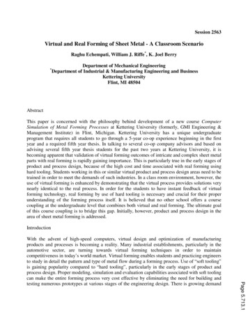
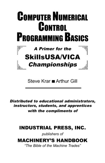
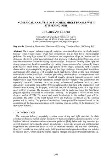
J. Adamus and P. LackiIn the calculations, different variants of frictional conditions and load were analysed, i.e.six values of blank-holder force were assumed: 200, 400, 600, 800, 1000 and 1200 kN, andtwo values of friction coefficients were assumed: 0.1 and 0.4.3.2 Numerical calculation resultsSome calculation results for the analysed process parameters are compiled in Table 2.Table 2: Basic process parameters and some calculation resultsFrictioncoefficient [-]0.10.4Holding-downforceFh-d c Difference in initialstrain and final panel width[mm] 110.0830.10Max. difference between positionnominal and drawn-part afterspring-back 79The plastic strain distribution is presented in Figures 4 and 5, respectively for the frictioncoefficient 0.1 and 0.4. The results are presented for three values of blank-holderforces, i.e.: Fh-d 200kN, Fh-d 600kN and Fh-d 1200kN are shown.Analysing the data given in Table 1 and the plastic strain distribution presented in Figures4 and 5, it can be seen that for the smaller value of friction coefficient 0.1 and the smallestblank-holder force Fh-d 200kN, the ribs are created by drawing the sheet material into the diecavities. As a result, the panel width decreases by nearly 2 mm. It means that in the case oflarger parts with several stiffening ribs, large sheet deformation arises therefore the sheetpanel will bend, warp and change shape. The subsequent numerical simulations showed thatthe greater the frictional coefficient and the greater the blank-holder force, the less sheet thatis drawn into the die cavity.For the higher friction coefficient 0.4 and the greatest blank-holder force Fh-d 1200kN,the ribs are formed only by material stretching and the plastic strains are distributedsymmetrically (Fig. 5 c). It suggests that the whole part will not undergo a large degree ofspringback.Thickness distributions are presented in Figures 6 and 7, respectively for the frictioncoefficient 0.1 and 0.4. The results are presented for three values of blank-holder forces,i.e.: Fh-d 200kN, Fh-d 600kN and Fh-d 1200kN are shown.208
J. Adamus and P. Lackia)YZX1.001.00max 0.054739Plastic strainb)0.070.060.050.780.780.040.03max 0.0615220.020.01c)0.000.480.48max 0.068045Figure 4: Plastic strain distribution for frictional coefficient 0.1 and blank-holder force:a) 200 kN, b) 600 kN, c) 1200 kN209
J. Adamus and P. Lackia)YZX0.500.50max 0.078478Plastic strainb)0.0850.0730.061 0.080.080.0490.036max 0.0805040.024c)0.0120.0000.050.05max 0.082747Figure 4: Plastic strain distribution for frictional coefficient 0.4 and blank-holder force:a) 200 kN b) 600 kN, c) 1200 kN210.
J. Adamus and P. Lackia)YZX1.001.00min 0.382155Thicknessmax 0.403178b)0.4050.4000.780.395 0.780.3900.385min 0.3786760.380max 0.401364c)0.3750.3700.480.48min 0.378676max 0.401364Figure 6: Thickness distribution [mm] for frictional coefficient 0.1 and blank-holder force:a) 200 kN, b) 600 kN, c) 1200 kN211.
J. Adamus and P. Lackia)YZX0.500.50min 0.373166Thicknessmax 0.400711b)0.4050.4000.080.395 0.080.3900.385min 0.3724050.380max 0.400088c)0.3750.3700.050.05min 0.371765max 0.400079Figure 7: Thickness distribution [mm] for frictional coefficient 0.4 and blank-holder force:a) 200 kN, b) 600 kN, c) 1200 kN212.
J. Adamus and P. LackiBy analysing the thickness distributions, it can be seen that the greater the frictionalcoefficient and the greater the blank-holder force, the fewer changes in the thickness of theflat part of the sheet. It also suggests that the whole part will not undergo a large degree ofspringback. Thus, if we want to avoid bending or twisting and losing the original part shape, itis necessary to create such forming conditions that the stiffening ribs are shaped only bymaterial stretching. It is necessary to avoid drawing the material from the flat part of the sheetinto the die cavity.4CONCLUSIONSAccording to the numerical calculation results it can be stated that both holding down forceand friction coefficient value, which are assumed on the contact surfaces, are very importantfor the forming process. These process parameters affect plastic strain distribution as well asthinning of the deformed sheet essentially. It is observed that the greater the frictionalcoefficient and the greater the blank-holder force, the fewer changes in thickness of the flatpart of the sheet. Therefore, it is advised to increase surface roughness by e.g. sand blasting toincrease the friction coefficient. The higher the frictional coefficient, the lower the blankholder force needed, hence a smaller stamping press is required.ACKNOWLEDGEMENTS:Financial support of Structural Funds in the Operational Programme - Innovative Economy(IE OP) financed from the European Regional Development Fund - Project "Modern materialtechnologies in aerospace industry", Nr POIG.01.01.02-00-015/08-00 is gratefullyacknowledged.REFERENCES[1] Williams, J.C. and Starke, Jr E.A. Progress in structural materials for aerospace systems.[2][3][4][5][6][7][8][9]Acta Mater (2003) 51:5775–5799.Dursun, T. and Soutis, C. Recent developments in advanced aircraft aluminium alloys.Mater. Design (2014) 56:862–871.Aghion, E., Bronfin, B. and Eliezer, D. The role of the magnesium industry in protectingthe environment. J. Mater. Process. Tech. (2001) 117:381-385.Cui ,C., Hu, B.M., Zhao, L. and Liu, S. Titanium alloy production technology, marketprospects and industry development. Mater. Design (2011) 32:1684-1691.Yang, H., Fan, X.G., Sun, Z.C., Guo, L.G. and Zhan, M. Recent developments in plasticforming technology of titanium alloys. Science China Technological Sciences (2011)54/2:490-501.Adamus, J., Lacki, P. Investigation of sheet-titanium forming with flexible toolExperiment and simulation. Arch. Metall. Mater. 57/4 (2012): 1247–1252.Adamus, J., Lacki, P. and Motyka, M. EBW titanium sheets as material for drawn parts.Arch. Civ. Mech. Eng. (2015) 15: 142-47.Winowiecka, J., Więckowski, W. and Zawadzki, M. Evaluation of drawability of tailorwelded blanks made of titanium alloys Grade 2 Grade 5. Comp. Mater. Sci. (2013)77:108-113.Lacki, P., Adamus, J., Więckowski, W. and Winowiecka, J. Evaluation of drawability of213
J. Adamus and P. Lackititanium welded sheets. Arch. Metall. Mater. (2013) 58/1:139-143.[10] Lacki, P. Simulation of sheet-titanium forming of welded blanks. ComputationalPlasticity XII: Fundamentals and Applications - Proceedings of the 12th InternationalConference on Computational Plasticity - Fundamentals and Applications, COMPLAS2013.[11] Sinke, J., Iacono, C. and Zadpoor, A.A. Tailor made blanks for the aerospace industry.Int. J. Mater. Form. (2010) 3/1:849– 852.[12] Adamus, J. and Lacki, P. Analysis of forming titanium welded blanks. Comp. Mater. Sci.(2014) 94:66-72.[13] Huang, X. and Richards, N.L. Titanium activated diffusion brazing technology formanufacture of titanium honeycomb structures - a statistical study. Supplement to theWelding Journal (2004): 73S-81S.[14] Kantha Rao, K., Jayathirtha Rao, K., Sarwade, A.G. and Sarath Chandra, M. Strengthanalysis on honeycomb sandwich panels of different materials. IJERA (2012) 2/3:365374.[15] Adamus, K., Kucharczyk, Z., Wojsyk, K. and Kudła, K. Numerical analysis of electronbeam welding of different grade titanium sheets. Comp. Mater. Sci. (2013) 77:286-294.[16] Lacki, P. and Adamus, K. Numerical simulation of the EBW process. Comput. Struct.(2011) 89:977-985.[17] Lacki, P. and Adamus, K. Numerical simulation of welding thin titanium sheets. KeyEng. Mat. (2013) 549: 407-414.[18] Lacki, P., Adamus, K. and Wieczorek, P. Theoretical and experimental analysis ofthermomechanical phenomena during electron beam welding process. Comp. Mater. Sci.(2014) 94:17–26.[19] Schubert, E., Klassen, M., Zerner, C., Walz, C. and Seplod, G. Light-weight structuresproduced by laser beam joining for future applications in automobile and aerospaceindustry. J. Mater. Process. Tech. (2001) 115:2-8.[20] Tavares, S.M.O. Welded aeronautical structures: cost and weight considerations.Structural Connections for Lightweight Metallic Structures. Mater. Sci. Forum (2012)8:219-237.[21] Bitondo, C., Prisco, U., Squillace, A., Giorleo, G., Buonadonna, P., Dionoro, G. andCampanile, G. Friction stir welding of AA2198-T3 butt joints for aeronauticalapplications. International Journal of Material Forming (2010) 3/1:1079-1082.[22] Derlatka, A., Kudła, K. and Makles, K. Numerical analysis of RFSSW joints. 11th WorldCongress on Computational Mechanics, WCCM 2014, 5th European Conference onComputational Mechanics, ECCM 2014 and 6th European Conference on ComputationalFluid Dynamics, ECFD (2014): 6807-6816.[23] Vaz, Jr. M., de Santi, Jr. N., Verran, G.O. and de Souza Neto, E.A. Numerical andexperimental assessment of ductile fracture in tensile and compressive-dominantprocesses. J. Mater. Process. Technol. (2006) 177:300–303.[24] Adamus, J. Numerical and experimental analysis of cold forming of titanium alloy sheets.Conference Proceedings of the 12th Int. Conf. on Computational Plasticity. Fundamentalsand Applications COMPLAS XII; ed. E. Oñate, D.R.J. Owen, D. Peric and B. Suárez(Eds), 3-5.IX.2013, Barcelona, Spain (2013) paper 456.[25] Gronostajski, J., Matuszak, A., Niechajowicz, A. and Zimniak, Z. The system for sheet214
J. Adamus and P. Lackimetal forming design of complex parts. J. Mater. Process. Technol. (2004) 157–158:502507.[26] Adamus, J. Theoretical and experimental analysis of the sheet-titanium forming process.Arch. Metall. Mater. (2009):705-709.[27] Motyka, M., Sieniawski, J. and Ziaja, W. Microstructural aspects of superplasticity in Ti6Al-4V alloy. Mater. Sci. Eng. (2014) 599:57–63.[28] Motyka, M. and Sieniawski, J. The influence of initial plastic deformation onmicrostructure and hot plasticity of α β titanium alloys. Archives of Materials Scienceand Engineering (2010) 41:95-103.[29] Adamus, J. Stamping of the titanium sheets. Key Eng. Mat. (2009) 410-411:279-288.[30] Adamus, J., Lacki, P., Motyka, M. and Kubiak, K. Investigation of sheet-titaniumdrawability. Proceedings of the 12th World Conference on Titanium - Ti 2011 (2012)1:337-341.[31] Adamus, J. and Lacki, P. Possibility of the increase in titanium sheets' drawability. KeyEng. Mat. (2013) 549:31-38.[32] Wang, Z.J., Song, H. and Wang, Z. (2008) Deformation behavior of TC1 titanium alloysheet under double-sided pressure. Trans. Nonferrous Met. Soc. China (2008) 18:72-76.[33] Bathini, U., Srivatsan, T.S., Patnaik, A.K. and Menzemer, C.C. Mechanisms GoverningFatigue, Damage, and Fracture of Commercially Pure Titanium for Viable AerospaceApplications. Journal of Aerospace Engineering (2011) 24/4:415-424.[34] Adamus, J. and Lacki, P. Forming of the titanium elements by bending. Comp. Mater.Sci. (2011) 50/4:1305-1309.[35] Shen, L., Fan, Y., Huai, J., Han, T., Wang, W. and Liang, T. The study of bendingforming using finite element discretization. Proceedings of the 2nd InternationalConference on Electronic and Mechanical Engineering and Information Technology,EMEIT 2012, Atlantis Press, Paris, France, (2012): 464-467.[36] Mori, K.I., Murao, T., Harada, Y. and Matsuo, T. Multistage cold deep drawing of longpure titanium cups using coloured sheets for prevention of seizure. CIRP Ann-Manuf.Technol. (2003) 52(1):237-240.[37] PamStamp 2G v. 2011. User's Guide. (2011).215
sheet-titanium forming. In the paper, numerical analysis of forming a part of a large sheet panel will be presented. The numerical simulation will be performed using the PamStamp program specially dedicated to sheet-metal forming. The program is based on the finite element method (FEM). The