Transcription
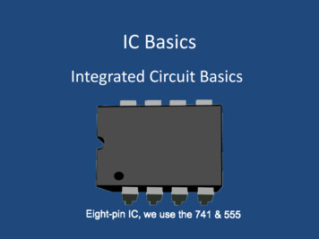
IC BasicsIntegrated Circuit Basics
Integrated circuits can be defined as:Integrated circuits (ICs) are, much astheir name would suggest, smallcircuits integrated into a plasticholder/"chip." Many ICs are reallyfairly simple -- often just consisting ofmultiple copies of a simple 2- or 3element circuit, in a small, handy,package.
The information on these subfamiliesis also found in lesson 3466-1 in Topic11. Here are some TTL "subfamilies": 74LXX -- low-power TTL (1/10 thespeed, 1/10 the power of "regular"TTL) 74HXX -- high-speed TTL (twice asfast, twice as much power)
74SXX -- Schottky TTL (for highfrequency uses) 74LSXX -- combination of low-power& Schottky, same speed as regularTTL, but at 1/5 the powerconsumption
CMOS -- Complimentary MetalOxide Silicon CMOS ICs use much less power thanTTL, plus they are fairly forgiving of"slop" in input voltage -- they'rehappy with anything between 3 and12 volts. (some, like 1381s, go lower)
CMOS, though, is much moresusceptible to damage from staticelectricity (Use a grounding strap toeliminate damage due to staticelectricity). This static is sometimescalled ESD (Electro Static Discharge).Get used to using “grounding straps”if you are working on computers orother static sensitive equipment.
CMOS comes in two types, withcorresponding numbering schemes:"CD40XX" metal gate CMOS, and"74CXX" silicon gate CMOS (notethat this second subfamily borrowsits numbering scheme from TTL ICs).
Metal gate CMOS (CD40XX)has arated working voltage of 3 - 15 V butcan be used down to 2V. Silicon gate CMOS (74CXX) logic hasa working voltage range of 2 - 6Vbut can be used to less than 1V. Formicrowatt power applications youwant to use the lowest possiblevoltage.
You will become familiar with themany gates in this lesson. You will become familiar with the ANDGate, OR Gate, NAND Gate, NOR Gateand the NOT Gate which is also known asan Inverter. You may also hear aboutBuffers in future lessons.
Pinout Diagrams The following slides illustrate some of thecommonly used ICs in Digital Electronics.The Pinout Diagrams illustrate theschematic symbol of the gate and whatpins are used from the gates to the leadsof the IC.
The Pinout Diagram is used to identifythe input and output leads of the ICs toaid in wiring the circuits on thebreadboards while in class and fortroubleshooting both while learning theoperation and when in the work shoptroubleshooting broken equipment.
TO-5 Package
TO-5 Package The TO-5 is a type of 'metal can' package(also known as 'metal header' package) forsemiconductor devices. It is hermeticallysealed to protect the device fromenvironmental factors such as contaminantsand moisture. The TO-5 is commonly usedin housing transistors and integratedcircuits with low lead counts such asoperational amplifiers
The TO-5 is made primarily of metal, withthe microchip mounted on the die pad ofits metal header and then sealed with ametal cap by high-current welding. Most TO-5 packages come with threeterminals, since the TO-5 is commonly usedin three-terminal devices such astransistors. However, TO-5 packages withmore terminals than this are also quitecommon.
The tab indicates pin 1. The leadclosest to the tab is pin 1.
8 Pin You must learn to recognize which pin isPin one on the ICs. The dot in the cornerof the chip designates pin 1. This is trueon the schematic symbol and on theactual IC. Count down, up, and acrossfrom pin 1.– Look at the next slide to see if you canrecognize which pin is pin 1 and the other pinnumbers.
Disc
Disc
7408 Quad Two-input AND
7432 Quad Two-input OR
7400 Quad Two-input NAND
Differences in Pinout Diagrams You must pay attention to the type of ICyou are working with. The next two diagrams are both QuadTwo-input NOR Gates.– The difference is that one is a TTL and the other isa CMOS IC.– Look at the difference in the Pinout Diagrams.
Nxt7402 Quad Two-input NOR
TTL4001 Quad Two-inputCMOS NOR
Gates can have more than two inputs The following pinout diagram is for athree input NAND Gate IC. There are also ICs that have gates withmore than three inputs. View the TTL Data Book to see a varietyof ICs and diagrams.
7410 Triple Three-input NAND
The below link is to download aTTL Data BookYou should be able to copy and pastethe link into a browser to open. 0xTVFRMX0RhdGFfREwxMjEtRC5wZGY
Questions?
References 3466-1 (Lesson) Conan the Librarian. (2003, July09). the basics of integratedcircuits. Retrieved fromhttp://www.solarbotics.net/bftgu/starting elect ic.html
www.SiliconFarEast.com. (2008). To-5package. Retrieved fromhttp://www.siliconfareast.com/to5.htm
The End.Developed and Produced by theInstructors in the CIE InstructionDepartment. Copyright 12/2011All Rights Reserved / Dec. 2011
Dec 20, 2011 · IC Basics Integrated Circuit Basics . Integrated circuits can be defined as: Integrated circuits (ICs) are, much as their name would suggest, small . View the TTL Data Book to see a variety of ICs and diagrams. 7410 Triple Three-input NAND . The b


![History of Electronics electricity [Read-Only]](/img/18/history-20of-20electronics-20-20electricity.jpg)