Transcription
chapter 1INTRODUCTIONTO DRIVETRAINSLEARNING OBJECTIVESKEY TERMSAfter studying this chapter, the reader shouldAll-wheel drive (AWD) 16Manual transmission 8be able to:Automatictransmission 9Overdrive 7Bevel gear 6Pitch diameter 4Clutch 8Planet carrier 11Constant-velocity (CV)joint 14Planetary gear set 11Differential 14Dynamometer 4Discuss the types of manual transmissions andRear-wheel drive(RWD) 13Drive axle 14transaxles that are currently in use.Ring gear 11Driveshaft 14Spiral bevel gear 6Discuss automatic transmissions and the plane-Final drive 13Spur gear 5tary gear sets used for automatic transmissions.Four-wheel drive(4WD) 16Sun gear 11Front-wheel drive(FWD) 13Torque converter 111.Define torque, and explain the relationshipbetween torque and horsepower.2.Describe the various gear types and their effecton speed, torque and direction of rotation.3.Explain gear ratios and their effect on vehicleoperation.4.5.6.Compare rear-wheel drive, front-wheel drive,four-wheel drive, and all-wheel drive systems.7.Explain the characteristics of drive shafts anddrive axle assemblies.Gear ratio 7Half shaft 13Helical gear 5Horsepower 3Hypoid gear 6Pinion gear 8Power transfer unit 16Torque 2Transaxle 13Transfer case 16Transmission 8Universal joint(U-joint) 14Worm gear 61M01 HALD6797 07 SE C01.indd 109/11/16 12:02 pm
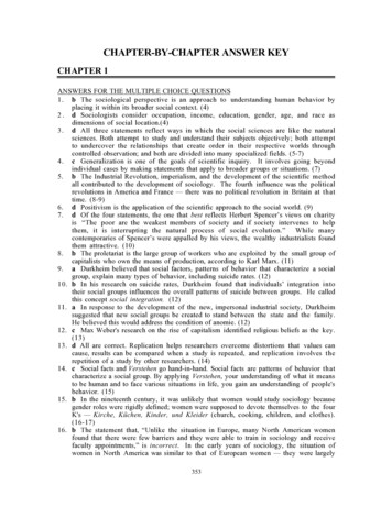
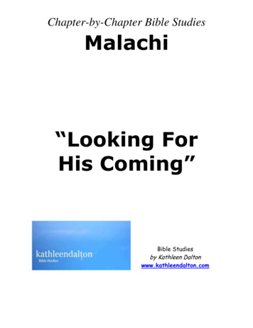
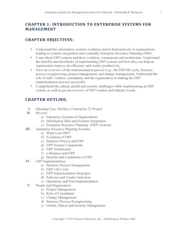
?DRIVETRAINSPURPOSE AND FUNCTIONFREQUENTLY ASKED QUESTIONIs It Lb-Ft or Ft-Lb of Torque?The purpose of a vehicledrivetrain is to transfer power from the engine to the drivewheels. The drivetrain, also called a powertrain, servesthe following functions:The unit for torque is expressed as a force times thedistance (leverage) from the object. Therefore, theofficial unit for torque is lb-ft (pound-feet) or Newtonmeters (a force times a distance). However, it is com- It allows the driver to control the power flow. It multiplies the engine torque. It controls the engine speed.monly expressed in ft-lb and most torque wrenchesare labeled with this unit.UNITS OF TORQUETORQUEEngine torque is developed whencombustion pressure pushes a piston downward to rotate thecrankshaft. SEE FIGURE 1–1.DEFINITIONTorque is a rotating or twisting force that mayor may not result in motion. A vehicle moves because of thetorque the drive axle exerts on the wheels and tires to makethem rotate. Being a form of mechanical energy, torque cannotbe created or destroyed—it is converted from one form ofenergy to another form of energy.The amount of torque produced will vary depending onthe size and design of the engine and the throttle opening.Torque is measured in pounds-feet (lb-ft) or Newton-meters(N-m). One Newton-meter of torque is equal to 0.737 lb-ft. Afactor that greatly affects drivetrain design is that very little orno torque is developed at engine speeds below 1000 RPM(revolutions per minute). An engine begins producing usabletorque at about 1200 RPM and peak torque at about 2500 to4000 RPM, with an upper usable speed limit of 5000 to 7000RPM. The gear ratios in the transmission and drive axle areused to match the engine speed and torque output to the ve-LENGTH INFEEThicle speed and torque requirements. SEE FIGURE 1–2.DRIVE VS. DRIVEN GEARSPULLING FORCEIN POUNDSThe drive gear is the gearthat is the source of the engine torque and rotation. The drivengear is the gear that is driven or rotated by the drive gear.Two gears meshed together are used to transmit torque andTWISTING FORCE—TORQUE IN FOOT-POUNDSrotational motion. The driven gear can then rotate yet anothergear. In this case, the second gear becomes the drive gear andCOMBUSTION PRESSUREthe third gear is the driven gear.TORQUE MULTIPLICATIONThe gear teeth are cut pro-portional to the diameter of the gear. If one of two mating gearswas twice as large as the other, it would have twice as manyteeth. For example, if the smaller gear has 10 teeth, a gear twiceas large will have 20 teeth. If the teeth of these gears are interTORQUEmeshed, 10 teeth of each gear will come into contact when thesmaller gear rotates one revolution. This will require one revolution of the small gear and one-half revolution of the larger gear.It will take two revolutions of the small gear to produce oneFIGURE 1–1 Torque, a twisting force, is produced when youpull on a wrench. An engine produces torque at the crankshaftas combustion pressure pushes the piston downward.2revolution of the larger gear. This is a gear ratio of 2:1, assumingthat the small gear is the drive gear. To determine a gear ratio,divide the driven gear by the driving gear. SEE FIGURE 1–3.CHAPTER 1M01 HALD6797 07 SE C01.indd 209/11/16 12:02 pm
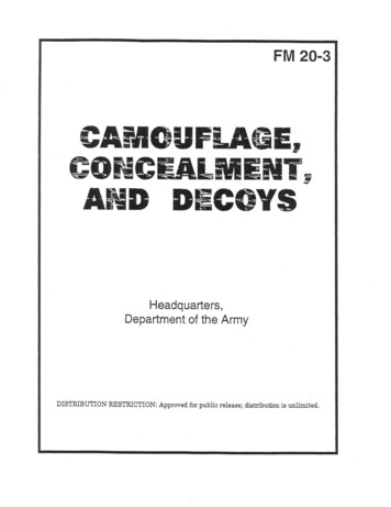
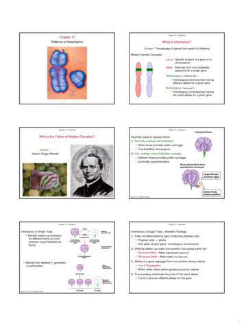
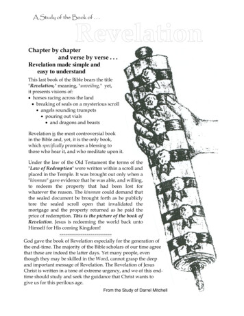
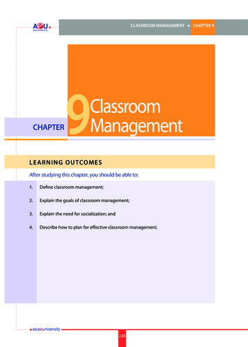
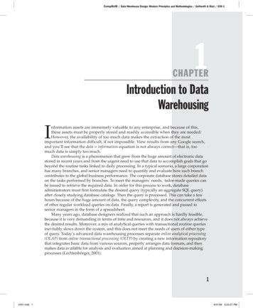
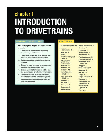
TORQUE (FOOT-POUNDS)RPMFIGURE 1–2 The torque produced by a 5.7 L engine as plotted on a graph. Note that the engine begins producing usable torqueat 1000 to 1200 RPM and a maximum torque (381 ft-lb) at 3500 RPM. The torque produced by the engine decreases at higherRPM due to a decrease in volumetric efficiency.24 TEETH ON DRIVEN GEAR If the speed is reduced, torque will increase by the sameamount. If speed is increased, torque will decrease by the sameamount.For example, if the driving gear has 20 lb-ft (27 N-m) oftorque at 500 RPM and the ratio is 2:1, the driven gear will have40 lb-ft (54 N-m) of torque (twice as much) at 250 RPM (half thespeed).12 TEETH ON DRIVING GEARFIGURE 1–3 Gear ratio is determined by dividing the number ofteeth of the driven (output) gear (24 teeth) by the number of teethon the driving (input) gear (12 teeth). The ratio illustrated is 2:1.HORSEPOWERDEFINITIONwork. Power equals work divided by time. GEARS ARE LEVERSWork is done when a certain amount of mass (weight) ismoved a certain distance by a force. Whether the object isTorque is increased because of themoved in 10 seconds or 10 minutes does not make a dif-length of the gear lever, as measured from the center of theference in the amount of work accomplished, but it doesgear. Think of each tooth as a lever, with the fulcrum beingaffect the amount of power needed. SEE FIGURE 1–4.the center of the gear. The lever lengths of the two gears canprovide leverage much like that of a simple lever. Physics doesThe term power means the rate of doing Power is expressed in units of foot-pounds per minute.not allow energy to become lost in a gear set, other than what isOne horsepower is the power required to move 550lost as heat in overcoming friction. Therefore, whatever powerpounds one foot in one second, or 33,000 pounds onethat comes in one shaft, goes out through another.foot in one minute (550 lb 60 sec 33,000 lb). ThisI N T RO D U C T I O N T O D RIVET RA IN SM01 HALD6797 07 SE C01.indd 3309/11/16 12:02 pm
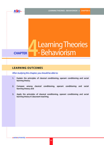
PITCH DIAMETER10 FEET100 LBSPITCH DIAMETER OFDRIVING GEARPOINT AFIGURE 1–4 Work is calculated by multiplying force timesdistance. If you push 100 pounds 10 feet, you have done1,000 foot-pounds of work.200POUNDS(91 KG)POINT CPOINT BPITCH DIAMETER OFDRIVING GEARFIGURE 1–6 The pitch diameter is the effective diameter ofthe gear. Note how the contact points slide on the gear teethas they move in and out of contact.165 FEET(50 M)165 FEET(50 M)PERMINUTETECH TIPHow to Explain the Difference betweenFIGURE 1–5 One horsepower is equal to 33,000 footpounds (200 lbs 165 ft) of work per minute.Horsepower and TorqueAs Carroll Shelby, the well-known racer and businessowner, said, “Horsepower sells cars, but torque winsis expressed as 550 foot-pounds (ft-lb) per second orraces.” Torque determines how fast the vehicle will33,000 foot-pounds per minute. SEE FIGURE 1–5.HORSEPOWER AND TORQUE RELATIONSHIPaccelerate, and horsepower determines how fast thevehicle will go.Todetermine horsepower, a dynamometer is used to measurethe amount of torque an engine can produce at various pointsits effect. A gear set can increase torque, but it will decreasethrough its operating range. The formula used to convert torquespeed by the same amount.at a certain revolution per minute (RPM) into a horsepowerreading isHorsepower Torque RPM/5,252NOTE: To determine how the constant “5,252” was derived, perform an Internet search to see an explanation.The various readings are then plotted into a curve. A typical horsepower and torque curve shows us that an engine doesnot produce very much torque at low RPM. The most usabletorque is produced in the mid-RPM range. Torque decreaseswith an increase in horsepower at a higher RPM.The torque from an engine can be increased or decreasedthrough the use of gears, belts, and chains. Gears, belts, orchains cannot increase horsepower; they can only modify4GEARSTERMINOLOGYThe effective diameter of a gear is thepitch diameter (or pitch line). SEE FIGURE 1–6.The pitch diameter is the diameter of the gear at the pointwhere the teeth of the two gears meet and transfer power. Thegear teeth are shaped to be able to slide in and out of meshwith a minimum amount of friction and wear. Major pointsinclude: Driven and driving gears will rotate in oppositedirections.CHAPTER 1M01 HALD6797 07 SE C01.indd 409/11/16 12:02 pm
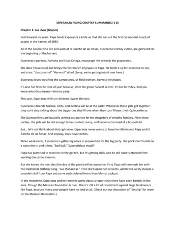
(a)EXTERNAL GEARS(b)INTERNAL ANDEXTERNAL GEARSFIGURE 1–7 (a) When one external gear drives another, the direction of rotation is always reversed. (b) When an external geardrives an internal gear, the two gears will rotate in the same direction.IDLERGEARSPUR GEARFIGURE 1–9 The teeth of a spur gear are cut parallel to theshaft, and this produces a straight pressure between thedriving and the driven gear teeth.is added. An idler gear changes the rotational direction butEXTERNAL GEARSdoes not affect the ratio. SEE FIGURE 1–8.FIGURE 1–8 An idler gear reverses the direction of rotation sothat the driving and driven gears rotate in the same direction.GEAR TYPESGears come in different types depending onthe cut and relationship of the teeth to the shafts. External gears will always reverse shaft motion. If same-direction motion is required, the power will be allel shafts with teeth cut straight or parallel to the shaft. SEErouted through two gear sets. When power goes through a series of gears, an evennumber of gears (2, 4, 6, and 8) will cause a reversal indirection and an odd number of gears (3, 5, 7, and 9)will produce same direction of rotation. SEESpur gears—Spur gears, the simplest gears, are on par- FIGURE 1–9.Helical gear—Helical gears are the most used of allgears used in transmissions. These gears have teeth cutin a spiral or helix shape. SEE FIGURE 1–10.Helical gears are quieter than spur gears, but gener-ate axial or end thrust under a load. A helical gear is stron-FIGURE 1–7.ger than a comparable-sized spur gear and has an almostREVERSING DIRECTION OF ROTATIONExternal gearsreverse the direction of rotation when the drive gear transferscontinuous power flow because of the angled teeth. SEEFIGURE 1–10.power to the driven gear. When it is necessary to change theNOTE: When discussing gears, a pinion gear is theratio without changing the direction of power flow, an idler gearsmaller gear of a pair.I N T RO D U C T I O N T O D RIVET RA IN SM01 HALD6797 07 SE C01.indd 5509/11/16 12:02 pm
AXIAL THRUSTOF DRIVING GEARAXIAL THRUSTOF DRIVEN GEARHELICAL GEARFIGURE 1–10 The teeth of a helical gear are cut on a slant, and this produces an axial or side thrust.RINGGEARCENTERLINEOFFSETFIGURE 1–11 Bevel gears are commonly used indifferentials. Bevel gears—Bevel gears are used on nonparallel shafts.The outer edge of the gear must be cut on the angle thatbisects the angle of the two shafts. In other words, if the?FREQUENTLY ASKED QUESTIONWhat Is a “Rock Crusher” Transmission?the same size, the outer edge of the gears will be cut atA manual Muncie (M22) four-speed manual trans-45 . The simplest bevel gears have teeth cut straight andmission in the muscle car era, was called the rockare called spur bevel gears. They are inexpensive butcrusher because it used straight cut spur gears.Spiral bevel gears—Spiral bevel gears, like helical gears,have curved teeth for quieter operation. FIGURE 1–12 A hypoid gear set uses a pinion gear that islocated below the centerline of the ring gear and is commonlyused in drive axles.two shafts meet at an angle of 90 and the two gears arenoisy. SEE FIGURE 1–11. PINIONGEARHypoid gear—A variation of the spiral bevel gear is thehypoid gear, also called an offset-bevel gear. Hypoid gearsare used in most drive axles and transaxles that have lon-It was designed as a racing transmission because by using spur gears, the end thrust loadswere reduced. However, spur gears are noisy andsounded like rocks being chewed up so therefore,the slang term “rock crusher” for this once populartransmission.gitudinal mounted engines. The hypoid gear design places 6the drive pinion gear lower in the housing (below the cen-sensor drives. To determine the ratio of a worm gear,terline) of the ring gear and axle shafts. SEEdivide the number of teeth on the wheel by the pitch ofFIGURE 1–12.the worm gear. For example, a single-pitch worm gearWorm gear—A gear set used with shafts that cross eachtooth driving a 20-tooth ring gear will have a ratio of 20:1,other but do not intersect is the worm gear. The worma very low ratio, and the wheel does not have to be 20gear or drive pinion is cut in a rather severe helix, muchtimes larger than the worm gear. A 20:1 ratio in most gearlike a bolt thread, and the ring gear or wheel is cut almostsets requires the driven gear to be 20 times larger thanlike a spur gear. Worm gears are used in vehicle speedthe driving gear. SEE FIGURE 1–13.CHAPTER 1M01 HALD6797 07 SE C01.indd 609/11/16 12:02 pm
50 T1st Gear, 2.5:120 T40 T2nd Gear, 2:120 T40/20 2FIGURE 1–13 A worm gear set is also used to transmitpower between angled shafts.50/20 2.520 T20/20 13rd Gear, 1:1GEAR RATIOS20 T20 T20 T16 T16/20 0.816 T4th Gear, 0.8:150 TReverse, 3.125:1TERMINOLOGYGear ratios are determined by the50/16 3.125following methods: Dividing the number of teeth on the driven gear (output)by the number of teeth on the driving gear (input). Most ofthe time, this means dividing a larger number, such as 20,by a smaller number, such as 5. In this case, 20 5 4,so the ratio will be 4:1. Gear ratio driven gear/drive gear. The driving gear will turn four times for each revolution ofFIGURE 1–14 The gear ratio is determined by dividing thenumber of teeth on the driven (output) gear by the number ofteeth on the driving (input) gear.?FREQUENTLY ASKED QUESTIONthe driven gear. This results in a speed reduction and aWhat Is the Relationship between Speed andtorque increase. The speed of the output will be 4 timesGear Ratio?slower than the input speed but, the output torque willThe following formulas can be used to determine the ve-be four times more than the input torque. The higher thehicle speed based on the gear ratio and engine speed,ratio number, the lower the gear ratio. A 5:1 ratio is higheror the engine speed based on the gear ratio and MPH:numerically, but, in terms of speed of the driven gear, it isa lower ratio than 4:1. SEE FIGURE 1–14.Most of the time, the ratio will not end up as whole numbers. It will be something like an 11-tooth driving gear and a19-tooth driven gear, which results in a ratio of 19 divided by11, which equals 1.7272727 and can be rounded off to 1.73.COMMONLY USED RATIOS Engine RPM (MPH gear ratio 336) tirediameterNOTE: The constant 336 is used to convert theunits from inches (tire diameter) to feet and MPHto feet per hour.The automotive industrycommonly rounds off gear ratios to two decimal points.Drivetrain engineers usually do not use even ratios like 3:1 or 4:1but instead use ratios that are at least 10 percent greater or lessthan even numbers. An even ratio, like 3:1, repeats the samegear tooth contacts every third revolution. If there is a damagedtooth, a noise will be repeated continuously, and most driverswill not like the noise. A gear set with a ratio such as 3.23:1 iscalled a hunting gear set, and a tooth of one gear contacts all ofthe other gear teeth, which produces quieter operation.OVERDRIVE MPH (RPM tire diameter) (gear ratio 336)reduction in torque. This is called an overdrive. The ratio iscomputed by dividing 5 by 20, 5 20 0.25, so the ratio wouldbe expressed as 0.25:1. The driving gear will turn 0.25 or onefourth of a revolution for each turn of the driven gear. Note thata gear ratio is always written with the number 1 to the right ofthe colon. This represents one turn of the output gear, while thenumber to the left represents the revolutions of the input gear.CALCULATING OVERALL RATIOSWhen power goesthrough more than one gear set, two or more ratios are inIf the driving gear has more teeth (20) thanvolved. In most cases, the simplest way to handle this is tothe driven gear (5), there will be an increase in speed and afigure the ratio of each set and then multiply the ratios. AnI N T RO D U C T I O N T O D RIVET RA IN SM01 HALD6797 07 SE C01.indd 7709/11/16 12:02 pm
B The smaller gear(s) in a gear set may also be called apinion gear. AAll gear sets must have backlash to prevent binding. SEEFIGURE 1–15.TRANSMISSIONSBACKLASHPURPOSE AND FUNCTIONA - B BACKLASHFIGURE 1–15 Backlash is the clearance between the teethof two meshing gears. There has to be some clearance (backlash) to prevent the gears from getting into a bind conditionwhen they are transmitting torque.The purpose and function ofgears in a transmission include the following: Low/first gear must provide enough torque to get thevehicle moving. High gear should provide an engine speed for fuel-efficientoperation at highway speeds.example of this is a vehicle with a first-gear ratio of 2.68:1and a rear axle ratio of 3.45:1. The overall ratio in first gear is2.68 3.45 or 9.246:1. The engine will rotate at a speed that is 9.246 timesthe other transmission gears would be figured in thesame manner.GEAR SET SUMMARYoverrevving the engine before the shift or lugging theTRENDSThe majority of vehicles up to the 1970s used three-speed transmissions while some added an overdrive unit for afourth gear ratio to lower engine RPM at cruise speeds. As theneed to improve fuel economy and reduce exhaust emissionshas improved, four-, five-, and six-speed transmissions haveTypical rules about gear setsinclude the following:Two mated external gears will always rotate in oppositedirections.been introduced to provide lower first gears, overdrive, and/orsmaller steps between gear ratios.MANUAL TRANSMISSIONS Gear sets will multiply torque, but at a reduced speed. An idler gear allows the drive and driven gears to rotate inPURPOSE AND FUNCTIONthe same direction.also called a standard transmission, is constructed with aTo find the ratio, divide the driven gear by the drivegroup of paths through which power can flow with each pathgear.used being a different gear ratio. SEE FIGURE 1–16. When power transfers through an even number (two orfour) of gears, the input and output gears will rotate inopposite directions. When power transfers through an uneven number (one,three, or five) of gears, the input and output gears willrotate in the same direction. A manual transmission,Synchronizer assemblies or sliding gears and the shiftlinkage are used to control or engage the power paths.CLUTCHEngine power must be stopped when making ashift in a manual transmission. The clutch is used to stop thepower flow to allow the transmission to be shifted. It is alsoused to ease the engagement of the power flow when theTo find the overall ratio of multiple gear sets, multiply thevehicle starts from a standstill. The slight slippage as the clutchratios of the gear sets.engages allows the engine speed to stay up where it producesTwo gears transferring power push away from eachusable torque as the vehicle begins moving.other in an action called gear separation. The gear8adequate acceleration while minimizing the potential ofengine after the shift.faster than the rear axle shafts. The overall ratios for The intermediate ratios should be spaced to provideAt the same time there will be 9.246 times as muchtorque at the rear wheels than the engine produced. Most vehicles use a foot-pedal-operated single-plateseparation force (thrust) is proportional to the torqueclutch assembly that is mounted on the engine flywheel. Whenbeing transferred.the pedal is pushed down, the power flow is disengaged andCHAPTER 1M01 HALD6797 07 SE C01.indd 809/11/16 12:02 pm
FIGURE 1–16 A manual transmission provides several gearratios and a method to shift them.?FREQUENTLY ASKED QUESTIONWhat Is a “Close-Ratio” Transmission?Gear ratio spread (GRS), is the difference betweenthe lowest and highest ratios or, in other words,the overall range of the transmission gear ratios. Intransmissions, it is fairly easy to visualize the differ-FIGURE 1–17 A Muncie four-speed manual transmission ona restored muscle car is an example of a close-ratio manualtransmission.when the pedal is released, power can flow from the engine to the transmission through the engaged clutch. SEEFIGURE 1–18.A UTOMATICTRANSMISSIONS ence between a 3.59:1 first gear and a 0.83:1 fifthgear. Gear ratio spread is determined by dividingthe low gear ratio by the high gear ratio. The GRSfor the gear transmission is 3.59 0.83 4.33.RPM change/drop is fairly easy to determine: Subtract the higher ratio from the lower ratio anddivide the product by the lower ratio. A close-ratio Muncie four-speed has ratiosspaced fairly close together (25% or less), closerthan the wide-ratio version. SEE FIGURE 1–17.PURPOSE AND FUNCTIONThe purpose and functionof an automatic transmission is to provide the forward andreverse gear ratios needed without requiring the driver tomake the change in gearing as with a manual transmission. Anautomatic transmission has various gear ratios, but the paths ofpower flow are different from those of a manual transmission.SHIFT MODESThe transmission provides the variousgear ratios for forward and reverse operations as well as twomethods for the engine to run without moving the vehicle. Mostautomatic transmissions and transaxles include the followingshift modes. SEE FIGURE 1–19.?FREQUENTLY ASKED QUESTIONWhat Is an Automated Manual Transmission?An automated manual transmission is a type of automatic transmission/transaxle that uses two clutchesand a manual transmission-type gears and is shifted Park. In the park position, the output shaft is locked tothe case of the transmission/transaxle which keeps thevehicle from moving. No power is transmitted through theunit so the engine can remain running while the vehicle isheld stationary.In the park positionhydraulically by computer-controlled solenoids. This1. The engine can be started by the driver.type of transmission is commonly called a dual clutch2. To move the shifter out of the park position on a lateor an electronically controlled manual transmission.model vehicle, the brake pedal must be depressed torelease the transmission shift interlock.I N T RO D U C T I O N T O D RIVET RA IN SM01 HALD6797 07 SE C01.indd 9909/11/16 12:02 pm
CLUTCH COVERMOVEMENT TOWARDSFLYWHEEL REMOVES CLAMPLOAD FROM CLUTCH URE 1–18 (a) A clutch cover (pressure plate assembly) is bolted onto the flywheel with the clutch disc between them. Therelease bearing and fork provide a method to release (disengage) the clutch. (b) When the clutch is engaged, the disc is squeezedagainst the flywheel by the pressure plate. Releasing the clutch separates the disc from the flywheel and pressure plate. Overdrive (OD). The OD is the normal position for theshift selector for most driving conditions. This positionallows the transmission or transaxle to shift through allforward gears as needed for the best fuel economy andlowest exhaust emissions.NOTE: The overdrive button used on many automatic transmissions is used to turn off overdrive andis used while towing or when driving in city traffic toprevent the transmission from shifting in and out ofoverdrive. Drive (D). The D position includes the overdrive ratios inmost vehicles. If there is an overdrive shift mode, however,FIGURE 1–19 The gear selector is often called the “PRNDL,”pronounced “prindle,” regardless of the actual letters or numbersused.then D is used to provide all forward gears except overdrive.Use this position when driving on the highway. Third (3). In third position the transmission/transaxlewill upshift normally to third gear, but will not upshift to Reverse. The reverse gear selector position is used toa higher gear. When the third position is selected whilemove the vehicle in reverse. Reverse usually uses a geardriving in a higher gear, the transmission will downshiftratio similar to first gear.into third if the vehicle speed is low enough to preventNeutral. In the neutral position, no torque is being trans-the engine from being overrevved. This gear selection ismitted through the automatic transmission/transaxle. Inused for gentle grades at a moderate vehicle speed whenengine braking is needed.this position the engine can be started by the driver. 10Second (2). The second position is used for slowing theCAUTION: The vehicle is free to roll when thevehicle while descending long grades. In this gear selec-gear selector is placed in the neutral position un-tion, the vehicle speed is controlled and the engine speedless the brake pedal is depressed to prevent theis increased to provide engine braking. This gear selectionvehicle from moving.is used for the gentle grades at a moderate vehicle speed.CHAPTER 1M01 HALD6797 07 SE C01.indd 1009/11/16 12:02 pm
FLEXPLATE(ATTACHED TOENGINE CRANKSHAFT)TORQUE CONVERTERFIGURE 1–20 A torque converter is attached to the engine crankshaft and the other end is splined to the input shaft of the automatic transmission. The torque converter is used to transmit engine torque to the transmission, yet slip when the engine is at idlespeed. First (1 or Low). The first (or low) position is used forslowing the vehicle while descending steep grades. Inthis gear selection, the vehicle speed is controlled andengine braking is used to slow the vehicle. This gearselection is used for the steepest grades at the lowest3. Planet carrier—It holds the planet gears (also called pinions) in position. SEE FIGURE 1–21.Each of these gears can have two possible actions: Theycan rotate or stand still.The planet gears/pinions have the following three possibleactions.possible speed.1. They can rotate on their shafts in a stationary carrier andTORQUE CONVERTERSA torque converter replacesthe manual transmission clutch. It is a type of fluid couplingthat can release the power flow at slow engine speeds andalso multiply the engine torque during acceleration. Torqueconverters in newer vehicles include a friction clutch thatlocks up to eliminate slippage at cruising speeds, improvingfuel economy and reducing exhaust emissions. SEEFIGURE 1–20.PLANETARY GEAR SETSact like idler gears.2. They can rotate on their shafts in a rotating carrier; theplanet gears are walking.3. They can stand still on their shafts and rotate with thecarrier.Planetary gear sets are used and combined in a complexmanner so that transmissions with seven or eight speeds forward plus reverse are possible. Shifts are made by engagingMost automatic transmis-sions use planetary gear sets, which are a combination ofgears. When the gear set is assembled, the sun gear is in thecenter and meshed with the planet gears, which are locatedaround it, somewhat like the planets in our solar system. Thering gear is meshed around the outside of the planet gears.The three main members of the planetary gear set include thefollowing:or releasing one or more internal clutches that drive a gear setmember, or by engaging or releasing other clutches or bandsthat hold a gear set member stationary. An automatic transmission might have as many as seven of these power control units (clutches or bands). One-way clutches are also usedthat self-release and overrun when the next gear is engaged.The control units can operate without the interruption of thepower flow.1. Sun gear—It is the gear in the center.PLANETARY GEAR SET OPERATION2. Ring gear—It is also called an annulus gear or internalsets are so arranged that power enters through one of thegear.Planetary gearmembers and leaves through one of the other members whileI N T RO D U C T I O N T O D RIVET RA IN SM01 HALD6797 07 SE C01.indd 111109/11/16 12:02 pm
PLANET PINIONS(CARRIER)RING GEAR OUTPUTSUN GEAR INPUTSUN GEARPLANET CARRIER HELD IN REACTIONPLANET GEARS ROTATING ON THEIR AXESRING GEAR(INTERNAL GEAROR ANNULUS GEAR)(a)RING GEAR OUTPUTFIGURE 1–21 A typical planetary gear set showing the termsthat are used to describe each member.SUN GEAR HELD IN REACTIONPLANET CARRIER INPUTPLANET GEARS WALKING AROUNDRING GEARthe third member is held stationary in reaction. Power flow(b)through a planetary gear set is controlled by clutches, bands,and one-way clutches. One or more clutches will controlRING GEAR OUTPUTthe power coming to a planetary member and one or morereaction members can hold a gear set member stationary.The third planetary member will be the output. SEESUN GEAR INPUTFIGURE 1–22.PLANETARY GEAR SET RATIOSPLANET CARRIER INPUTA simple planetaryPLANET GEARS LOCKED, ROTATINGWITH THE CARRIERgear set can produce one of the following: A neutral if either the input clutch or reaction member isnot applied Two reduction ratios Two overdrive ratios Two reverse ratios, one a reduction and one an overdrive The reduction, overdrive, and reverse ratios will requireone driving member, one output member, and one reaction member in the gear set(c)FIGURE 1–22 (a) If the planet carrier is held with the sungear rotating, the planet gears simply rotate in the carrier andact as idler gears between the sun and ring gears. (b) If thesun or ring is held, the planet gears will walk around that stationary gear; they rotate on their shafts as the car
4 CHAPTER 1 is expressed as 550 foot-pounds (ft-lb) per second or 33,000 foot-pounds per minute. SEE FIGURE 1–5. HORSEPOWER AND TORQUE RELATIONSHIP To determine horsepower, a