Transcription
save as:101-200 Transistor circuits.pdfGo to: 1 - 100 Transistor CircuitsGo to: 100 IC Circuits86 CIRCUITS as of 28-5-2011See TALKING ELECTRONICS WEBSITEemail Colin Mitchell: talking@tpg.com.au
INTRODUCTIONThis is the second half of our Transistor Circuits e-book. It contains afurther 100 circuits, with many of them containing one or more IntegratedCircuits (ICs).It's amazing what you can do with transistors but when Integrated Circuitscame along, the whole field of electronics exploded.IC's can handle both analogue as well as digital signals but before theirarrival, nearly all circuits were analogue or very simple "digital" switchingcircuits.Let's explain what we mean.The word analogue is a waveform or signal that is changing (increasing anddecreasing) at a constant or non constant rate. Examples are voice, music,tones, sounds and frequencies. Equipment such as radios, TV's andamplifiers process analogue signals.Then digital came along.Digital is similar to a switch turning something on and off.The advantage of digital is two-fold.Firstly it is a very reliable and accurate way to send a signal. The signal iseither HIGH or LOW (ON or OFF). It cannot be half-on or one quarter off.And secondly, a circuit that is ON, consumes the least amount of energy inthe controlling device. In other words, a transistor that is fully turned ONand driving a motor, dissipates the least amount of heat. If it is slightlyturned ON or nearly fully turned ON, it gets very hot.And obviously a transistor that is not turned on at all will consume noenergy.A transistor that turns ON fully and OFF fully is called a SWITCH.When two transistors are cross-coupled in the form of a flip flop, any pulsesentering the circuit cause it to flip and flop and the output goes HIGH onevery second pulse. This means the circuit halves the input pulses and isthe basis of counting or dividing.Digital circuits also introduce the concept of two inputs creating a HIGHoutput when both are HIGH and variations of this.This is called "logic" and introduces terms such as "Boolean algebra" and"gates."Integrated Circuits started with a few transistors in each "chip" andincreased to whole mini or micro computers in a single chip. These chipsare called Microcontrollers and a single chip with a few surroundingcomponents can be programmed to play games, monitor heart-rate and doall sorts of amazing things. Because they can process information at highspeed, the end result can appear to have intelligence and this is where weare heading: AI (Artificial Intelligence).But let's crawl before we walk and come to understand how to interfacesome of these chips to external components.In this Transistor Circuits ebook, we have presented about 100 interestingcircuits using transistors and chips.In most cases the IC will contain 10 - 100 transistors, cost less than theindividual components and take up much less board-space. They also save alot of circuit designing and quite often consume less current than discretecomponents.In all, they are a fantastic way to get something working with the leastcomponentry.A list of of Integrated Circuits (Chips) is provided at the end of this book tohelp you identify the pins and show you what is inside the chip.Some of the circuits are available from Talking Electronics as a kit, butothers will have to be purchased as individual components from your localelectronics store. Electronics is such an enormous field that we cannotprovide kits for everything. But if you have a query about one of thecircuits, you can contact me.Colin MitchellTALKING ELECTRONICS.
talking@tpg.com.auTo save space we have not provided lengthy explanations of how thecircuits work. This has already been covered in TALKING ELECTRONICS BasicElectronics Course, and can be obtained on a CD for 10.00 (posted toanywhere in the world) See Talking Electronics website for more details:http://www.talkingelectronics.comMORE INTROThere are two ways to learn electronics.One is to go to school and study theory for 4 years and come out with allthe theoretical knowledge in the world but almost no practical experience.We know this type of person. We employed them (for a few weeks!). Theythink everything they design WILL WORK because their university professorsaid so.The other way is to build circuit after circuit and get things to work. Youmay not know the in-depth theory of how it works but trial and error getsyou there.We know. We employed this type of person for up to 12 years.I am not saying one is better than the other but most electronicsenthusiasts are not "book worms" and anyone can succeed in this field byconstantly applying themselves with "constructing projects." You actuallylearn 10 times faster by applying yourself and we have had techniciansrepairing equipment after only a few weeks on the job.It would be nothing for an enthusiast to build 30 - 40 circuits from ourprevious Transistor eBook and a similar number from this book. Many of thecircuits are completely different to each other and all have a building blockor two that you can learn from.Electronics enthusiasts have an uncanny understanding of how a circuitworks and if you have this ability, don't let it go to waste.Electronics will provide you a comfortable living for the rest of your lifeand I mean this quite seriously. The market is very narrow but new designsare coming along all the time and new devices are constantly beinginvented and more are always needed.Once you get past this eBook of "Chips and Transistors" you will want toinvestigate microcontrollers and this is when your options will explode.You will be able to carry out tasks you never thought possible, with a chipas small as 8 pins and a few hundred lines of code.As I say in my speeches. What is the difference between a "transistor man"and a "programmer?" TWO WEEKS!In two weeks you can start to understand the programming code for amicrocontroller and perform simple tasks such as flashing a LED andproduce sounds and outputs via the press of a button.All these things are covered on Talking Electronics website and you don'thave to buy any books or publications. Everything is available on the weband it is instantly accessible. That's the beauty of the web.Don't think things are greener on the other side of the fence, by buying atext book. They aren't. Everything you need is on the web AT NO COST.The only thing you have to do is build things. If you have any technicalproblem at all, simply email Colin Mitchell and any question will beanswered. Nothing could be simpler and this way we guarantee youSUCCESS. Hundreds of readers have already emailed and after 5 or moreemails, their circuit works. That's the way we work. One thing at a timeand eventually the fault is found.If you think a circuit will work the first time it is turned on, you are foolingyourself.All circuits need corrections and improvements and that's what makes agood electronics person. Don't give up. How do you think all the circuits inthese eBooks were designed? Some were copied and some were designedfrom scratch but all had to be built and adjusted slightly to make sure they
worked perfectly.I don't care if you use bread-board, copper strips, matrix board or solderthe components in the air as a "bird's nest." You only learn when the circuitgets turned on and WORKS!In fact the rougher you build something, the more you will guarantee it willwork when built on a printed circuit board.However, high-frequency circuits (such as 100MHz FM Bugs) do not likeopen layouts and you have to keep the construction as tight as possible toget them to operate reliably.In most other cases, the layout is not critical.TRANSISTORSMost of the transistors used in our circuits are BC 547 and BC 557. Theseare classified as "universal" or "common" NPN and PNP types with a voltagerating of about 25v, 100mA collector current and a gain of about 100. Somemagazines use the term "TUP" (for Transistor Universal PNP) or "TUN" (forTransistor Universal NPN). We simply use Philips types that everyonerecognises. You can use almost any type of transistor to replace them andhere is a list of the equivalents and pinouts:
CONTENTSred indicates 1-100 Transistor CircuitsAdjustable High Current Power SupplyAerial AmplifierAlarm Using 4 buttonsAudio Amplifier (mini)Automatic Battery ChargerBattery Charger - 12v AutomaticBattery Charger - Gell CellBattery Charger MkII - 12v trickle chargerBattery Monitor MkIBattery Monitor MkIIBike Turning SignalBeacon (Warning Beacon 12v)Beeper BugBlocking OscillatorBook LightBuck Regulator 12v to 5vCamera ActivatorCapacitor Discharge Unit MkII (CDU2) TrainsCapacitor Discharge Unit MkII - ModificationCar Detector (loop Detector)Car Light AlertCharger Gell CellCharger - NiCdChip Programmer (PIC) Circuits 1,2 3Circuit Symbols Complete list of SymbolsClap SwitchCode LockColour Code for Resistors - all resistorsConstant CurrentConstant Current Drives two 3-watt LEDsCrystal TesterDark Detector with beep AlarmDarlington TransistorDecaying FlasherDelay Turn-off - turns off a circuit after a delayDriving a LEDFading LEDFlasher (simple) 3 more in 1-100 circuitsFlashing Beacon (12v Warning Beacon)Fluorescent Inverter for 12v supplyFM Transmitters - 11 circuitsGell Cell ChargerHex BugH-BridgeHigh Current from old cellsHigh Current Power SupplyIncreasing the output currentInductively Coupled Power SupplyIntercomLatching A Push ButtonLatching RelayLED Detects lightLEDs on 240vLEDs Show Relay StateLimit SwitchesLow fuel IndicatorLow Mains Drop-outLow Voltage cut-outLow Voltage FlasherMains DetectorMains Night LightMake any capacitor valueMake any resistor valueMetal DetectorModel Railway timeNiCd ChargerPhase-Shift Oscillator - good designPhone BugPhone Tape-3Phone Tape-4 - using FETsPIC Programmer Circuits 1,2 3Powering a LEDPower ONPower Supplies - FixedPower Supplies - Adjustable LMxx seriesPower Supplies - Adjustable 78xx seriesPower Supplies - Adjustable from 0vPower Supply - Inductively CoupledPush-ON Push-OFFPWM ControllerQuiz TimerRailway timeRandom Blinking LEDsRectifying a VoltageResistor Colour CodeResistor Colour Code - 4, 5 and 6 BandsReversing a Motor & 2 & 3SequencerShake Tic Tac LED TorchSimple FlasherSimple Touch-ON Touch-OFF SwitchSirenSoft Start power supplySuper-Alpha Pair (Darlington Transistor)Sziklai transistorTelephone amplifierTelephone BugTouch-ON Touch-OFF SwitchTracking TransmitterTrack Polarity - model railwayTrain DetectorsTransformerless Power SupplyTransistor tester - Combo-2Vehicle Detector loop DetectorVHF Aerial AmplifierVoltage DoublerVoltage MultipliersVoyager - FM BugWailing SirenWater Level DetectorXtalTesterZapper - 160v1-watt LED1.5 watt LED3-Phase Generator5v from old cells - circuit 15v from old cells - circuit 25v Supply12v Battery Charger - Automatic12v Flashing Beacon (Warning Beacon)12v Supply
12v to 5v Buck Converter20 LEDs on 12v supply240v Detector240v - LEDsRESISTOR COLOUR CODESee resistors from 0.22ohm to 22M in full colour at end of book and another resistor table
RECTIFYING a VoltageThese circuits show how to change an oscillating voltage (commonly called AC) toDC. The term AC means Alternating Current but it really means Alternating Voltageas the rising and falling voltage produces an increasing and decreasing current.The term DC means Direct Current but it actually means Direct or unchangingVoltage.The output of the following circuits will not be pure DC (like that from a battery) butwill contain ripple. Ripple is reduced by adding a capacitor (electrolytic) to the output.
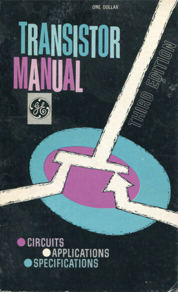
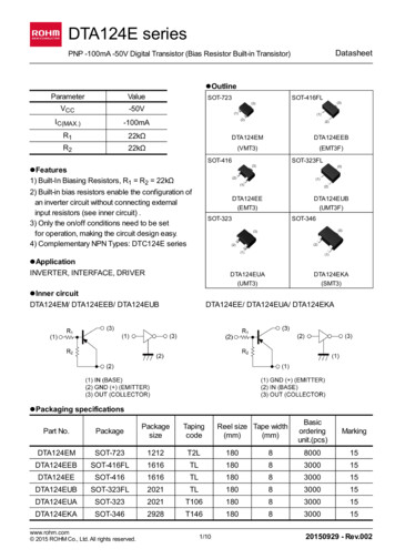
DARK DETECTOR with beep-beep-beep AlarmThis circuit detects darkness and produces a beep-beep-beep alarm. Thefirst two transistors form a high-gain amplifier with feedback via the 4u7 toproduce a low-frequency oscillator. This provides voltage for the secondoscillator (across the 1k resistor) to drive a speaker.3-PHASE SINEWAVE GENERATORThis circuit produces a sinewave and each phase can be tapped atthe point shown.TRANSFORMERLESS POWER SUPPLYThis clever design uses 4 diodes in a bridge to produce a fixedvoltage power supply capable of supplying 35mA.All diodes (every type of diode) are zener diodes. They allbreak down at a particular voltage. The fact is, a power diodebreaks down at 100v or 400v and its zener characteristic is notuseful.But if we put 2 zener diodes in a bridge with two ordinary powerdiodes, the bridge will break-down at the voltage of the zener.This is what we have done. If we use 18v zeners, the output willbe 17v4.When the incoming voltage is positive at the top, the left zenerprovides 18v limit (and the left power-diode produces a drop of0.6v). This allows the right zener to pass current just like a normal diode but the voltage available to it is just 18v. Theoutput of the right zener is 17v4. The same with the other half-cycle.The current is limited by the value of the X2 capacitor and this is 7mA for each 100n when in full-wave (as per thiscircuit). We have 10 x 100n 1u capacitance. Theoretically the circuit will supply 70mA but we found it will only deliver35mA before the output drops. The capacitor should comply with X1 or X2 class. The 10R is a safety-fuse resistor.The problem with this power supply is the "live" nature of the negative rail. When the power supply is connected asshown, the negative rail is 0.7v above neutral. If the mains is reversed, the negative rail is 340v (peak) above neutraland this will kill you as the current will flow through the diode and be lethal. You need to touch the negative rail (or thepositive rail) and any earthed device such as a toaster to get killed. The only solution is the project being powered mustbe totally enclosed in a box with no outputs.
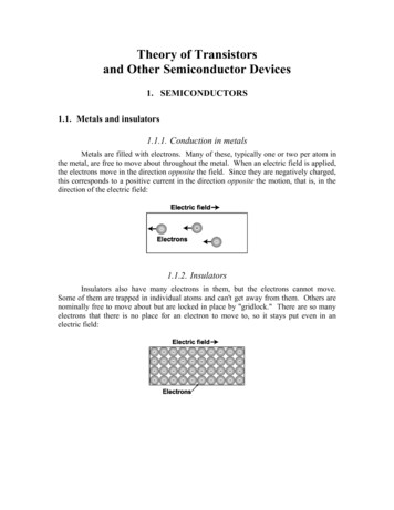
LEDs on240vI do not like any circuitconnected directly to 240vmains. However Christmastress lights have beenconnected directly to themains for 30 years withoutany major problems.Insulation must beprovided and the lights(LEDs) must be away fromprying fingers.You need at least 50 LEDsin each string to preventthem being damaged via a surge through the 1k resistor - if the circuit is turned on at the peak of the waveform. Asyou add more LEDs to each string, the current will drop a very small amount until eventually, when you have 90LEDs in each string, the current will be zero.For 50 LEDs in each string, the total characteristic voltage will be 180v so that the peak voltage will be 330v - 180v 150v. Each LED will see less than 7mA peak during the half-cycle they are illuminated. The 1k resistor will drop7v - since the RMS current is 7mA (7mA x 1,000 ohms 7v). No rectifier diodes are needed. The LEDs are the"rectifiers." Very clever. You must have LEDs in both directions to charge and discharge the capacitor. Theresistor is provided to take a heavy surge current through one of the strings of LEDs if the circuit is switched onwhen the mains is at a peak.This can be as high as 330mA if only 1 LED is used, so the value of this resistor must be adjusted if a smallnumber of LEDs are used. The LEDs above detect peak current.A 100n cap will deliver 7mA RMS or 10mA peak in full wave or 3.5mA RMS (10mA peak for half a cycle) inhalf-wave. (when only 1 LED is in each string).The current-capability of a capacitor needs more explanation. In the diagram on the left we see a capacitorfeeding a full-wave power supply. This is exactly the same as the LEDs on 240v circuit above. Imagine the LOADresistor is removed. Two of the diodes will face down and two will face up. This is exactly the same as the LEDsfacing up and facing down in the circuit above. The only difference is the mid-point is joined. Since the voltage onthe mid-point of one string is the same as the voltage at the mid-point of the other string, the link can be removedand the circuit will operate the same.This means each 100n of capacitance will deliver 7mA RMS (10mA peak on each half-cycle).In the half-wave supply, the capacitor delivers 3.5mA RMS (10mA peak on each half-cycle, but one half-cycle islost in the diode) for each 100n to the load, and during the other half-cycle the 10mA peak is lost in the diode thatdischarges the capacitor.You can use any LEDs and try to keep the total voltage-drop in each string equal. Each string is actually workingon DC. It's not constant DC but varying DC. In fact is it zero current for 1/2 cycle then nothing until the voltage risesabove the total characteristic voltage of all the LEDs, then a gradual increase in current over the remainder of thecycle, then a gradual decrease to zero over the falling portion of the cycle, then nothing for 1/2 cycle. Because theLEDs turn on and off, you may observe some flickering and that's why the two strings should be placed together.BOOK LIGHTThis circuit keeps the globeilluminated for a few seconds afterthe switch is pressed.There is one minor fault in thecircuit. The 10k should beincreased to 100k to increase the"ON" time.The photo shows the circuit builtwith surface-mount components:
CAMERA ACTIVATORThis circuit was designed for a customer who wanted to trigger a camera after ashort delay.The output goes HIGH about 2 seconds after the switch is pressed. The LED turnson for about 0.25 seconds.The circuit will accept either active HIGH or LOW input and the switch can remainpressed and it will not upset the operation of the circuit. The timing can be changedby adjusting the 1M trim pot and/or altering the value of the 470k.MAKE YOUR OWN:15 LEDs on Matrix boardThe transformer consists of 50 turns0.25mm wire connected to the pins.The feedback winding is 20 turns0.095mm wire with "fly-leads."1-WATT LEDThis circuit drives 15 LEDs to produce the same brightness as a 1-watt LED. The circuitconsumes 750mW but the LEDs are driven with high-frequency, high-voltage spikes, andbecome more-efficient and produce a brighter output that if driven by pure-DC.The LEDs are connected in 3 strings of 5 LEDs. Each LED has a characteristic voltage of3.2v to 3.6v making each chain between 16v and 18v. By selecting the LEDs we haveproduced 3 chains of 17.5v Five LEDs (in a string) has been done to allow the circuit to bepowered by a 12v battery and allow the battery to be charged while the LEDs areilluminating. If only 4 LEDs are in series, the characteristic voltage may be as low as 12.8vand they may be over-driven when the battery is charging. (Even-up the characteristicvoltage across each chain by checking the total voltage across them with an 19v supply and470R dropper resistor.) The transformer is shown above. It is wound on a 10mH choke with
the original winding removed. This circuit is called a "boost circuit." It is not designed todrive a single 1-watt LED (a buck circuit is needed).The LEDs in the circuit are 20,000mcd with a viewing angle of 30 degrees (many of the LEDspecifications use "half angle." You have to test a LED to make sure of the angle). Thisequates to approximately 4 lumens per LED. The 4-watt CREE LED claims 160 lumens (or40 lumens per watt). Our design is between 50 - 60 lumens per watt and it is a muchcheaper design.1.5 WATT LEDThe circuit below can be modified to drive up to 30white LEDs.The effectiveness of a LED array increases whenthey are spread out slightly and this makes themmore efficient than a single 1 watt or 2 watt LED.The two modifications to the circuit make the BC337work harder and this is the limit of the inductor. Thecurrent consumption is about 95mA.The winding details for the transformer are shownabove.30 LEDs on Matrix board
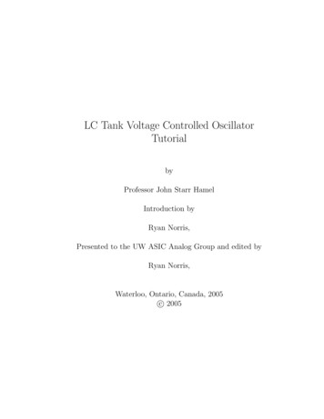
DRIVE 20 LEDs FROM 12v - approx 1watt circuitThis is another circuit that drives a number of LEDs or a single 1 watt LED. It is a "Buck Circuit"and drives the LEDs in parallel. They should be graded so that the characteristic voltage-dropacross each of them is within 0.2v of all the other LEDs. The circuit will drive any number from 1 to20 by changing the "sensor" resistor as shown on the circuit. The current consumption is about95mA @ 12v and lower at 18v. The circuit can be put into dim mode by increasing the driveresistor to 2k2. The UF4004 is an ultra fast 1N4004 - similar to a high-speed diode. You can use2 x 1N4148 signal diodes.The circuit will not drive two LEDs in series - it runsout of voltage (and current) when the voltageacross the load is 7v. It oscillates at approx 200kHz.Build both the 20 LED and 1 watt LED version andcompare the brightness and effectiveness.The photo of the 1 watt LED on the left must beheatsinked to prevent the LED overheating. Thephoto on the circuit diagram shows the LEDmounted on a heatsink and the connecting wires.A 1-watt demo board showing the complex step-up circuitry.This is a Boost circuit to illuminate the LED and is completely different to our design. It has beenincluded to show the size of a 1 watt LED.The reason for a Boost or Buck circuit to drive one or more LEDs is simple. The voltage across aLED is called a "characteristic voltage" and comes as a natural feature of the LED. We cannotalter it. To power the LED with exactly the correct amount of voltage (and current) you need asupply that is EXACTLY the same as the characteristic voltage. This is very difficult to do and so aresistor is normally added in series. But this resistor wastes a lot of energy. So, to keep the losesto a minimum, we pulse the LED with bursts of energy at a higher voltage and the LED absorbsthem and produces light. With a Buck circuit, the transistor is turned on for a short period of timeand illuminated the LEDs. At the same time, some of the energy is passed to the inductor so thatthe LEDs are not damaged. When the transistor is turned off, the energy from the inductor alsogives a pulse of energy to the LEDs. When this has been delivered, the cycle starts again.
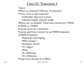
POWER SUPPLIES - FIXED:A simple power supply can be made with a component called a "3pin regulator or 3-terminal regulator" It will provide a very low rippleoutput (about 4mV to 10mV provided electrolytics are on the inputand output.The diagram above shows how to connect a regulator to create apower supply. The 7805 regulators can handle 100mA, 500mA and1 amp, and produce an output of 5v, as shown.These regulators are called linear regulators and drop about 4vacross them - minimum. If the current flow is 1 amp, 4watts of heatmust be dissipated via a large heatsink. If the output is 5v and input12v, 7volts will be dropped across the regulator and 7watts mustbe dissipated.
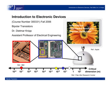
POWER SUPPLIES - ADJUSTABLE:The LM317 regulators are adjustable and produce an output from1.25 to about 35v. The LM317T regulator will deliver up to 1.5amp.POWER SUPPLIES - ADJUSTABLE using 7805:The 7805 range of regulators are called "fixed regulators" but theycan be turned into adjustable regulators by "jacking-up" their outputvoltage. For a 5v regulator, the output can be 5v to 30v.
POWER SUPPLIES - ADJUSTABLE from 0v:The LM317 regulator is adjustable from 1.25 to about 35v. To makethe output 0v to 35v, two power diodes are placed as shown in thecircuit. Approx 0.6v is dropped across each diode and this is wherethe 1.25v is "lost."5v POWER SUPPLYUsing the the LM317 regulator to produce 5v supply(5.04v):CONSTANT CURRENTThis constant current circuit can be adjusted to any value from a
few milliamp to about 500mA - this is the limit of the BC337transistor.The circuit can also be called a current-limiting circuit and is ideal ina bench power supply to prevent the circuit you are testing frombeing damaged.Approximately 4v is dropped across the regulator and 1.25v acrossthe current-limiting section, so the input voltage (supply) has to be5.25v above the required output voltage. Suppose you want tocharge 4 Ni-Cad cells. Connect them to the output and adjust the500R pot until the required charge-current is obtained.The charger will now charge 1, 2, 3 or 4 cells at the same current.But you must remember to turn off the charger before the cells arefully charged as the circuit will not detect this and over-charge thecells.The LM 317 3-terminal regulator will need to be heatsinked.This circuit is designed for the LM series of regulator as they have avoltage differential of 1.25v between "adj" and "out" terminals.7805 regulators can be used but the losses in the BC337 will be 4times greater as the voltage across it will be 5v.CONSTANT CURRENT DRIVES TWO 3WATT LEDsThis constant current circuit is designed to drive two 3-watt LuxeonLEDs. The LEDs require 1,000mA (1Amp) and have a characteristicvoltage-drop across them of about 3.8v. Approximately 4v isdropped across the LM317T regulator and 1.25v across the currentlimiting resistors, so the input voltage (supply) has to be 12.85v. A12v battery generally delivers 12.6v.The LM 317T 3-terminal regulator will need to be heatsinked.This circuit is designed for the LM series of regulator as they have avoltage differential of 1.25v between "adj" and "out" terminals.5v FROM OLD CELLS - circuit 1This circuit takes the place of a 78L05 3-terminal regulator. It produces a constant 5v @100mA. You can use any old cells and get the last of their energy. Use an 8-cell holder. Thevoltage from 8 old cells will be about 10v and the circuit will operate down to about 7.5v. Theregulation is very good at 10v, only dropping about 10mV for 100mA current flow (the 78L05has 1mV drop). As the voltage drops, the output drops from 5v on no-load to 4.8v and 4.6v on100mA current-flow. The pot can be adjusted to compensate for the voltage-drop. This type ofcircuit is called a LINEAR REGULATOR and is not very efficient (about 50% in this case). Seecircuit 2 below for BUCK REGULATOR circuit (about 85% efficient).
The regulator connected to a 12v batterypackThe regulator connected to a 9vbatteryThe battery snap plugs into the pins onthe 5v regulator board with the red leadgoing to the negative output of the boardas the battery snap is now DELIVERINGvoltage to the circuit you are powering.A close-up of the regulatormodule5v FROM OLD CELLS - circuit 2This circuit is a BUCK REGULATOR. It can take the place of a 78L05 3-terminal regulator, butit is more efficient. It produces a constant 5v @ up to 200mA. You can use any old cells andget the last of their energy. Use an 8-cell holder. The voltage from 8 old cells will be about 10vand the circuit will operate down to about 7.5v. The regulation is very good at 10v, only
dropping 10mV for up to 200mA output.INCREASING THE OUTPUT CURRENTThe output current of all 3-terminal regulators can be increased byincluding a pass transistor. This transistor simply allows the current to flowthrough the collector-emitter leads.The output voltage is maintained by the 3-terminal regulator but the currentflows through the "pass transistor." This transistor is a power transistor andmust be adequately heatsinked.Normally a 2N3055 or TIP3055 is used for this application as it will handleup to 10 amps and creates a 10 amp power supply. The regulator can be78L05 as all the current is delivered by the pass transistor.
SOFT STARTThe output voltage of a 3-terminal regulator can be designed to riseslowly. This has very limited application as many circuits do not likethis.TURN-OFF DELAYThese 4 circuits are all the same. They supply power to a project for a shortperiod of time. You can select either PNP or NPN transistors or Darlingtontransistors. The output voltage gradually dies and this will will produce weirdeffects with some projects.
LED DETECTS LIGHTThe LED in this circuit will detect light to turn on the oscillator. Ordinary red LEDs do notwork. But green LEDs, yellow LEDs and high-bright white LEDs and high-bright red LEDswork very well.The output voltage of the LED is up to 600mV when detecting very bright illumination.When light is detected by the LED, its resistance decreases and a very small currentflows into the base of the first transistor. The transistor amplifies this current about 200times and the resistance between collector and emitter decreases. The 330k resistor onthe collector is a current limiting resistor as the middle transistor only needs a very smallcurrent for the circuit to oscillate. If the current is too high, the circuit will "freeze."The piezo diaphragm does not contain any active components and relies on the circuit todrive it to produce the tone. A different LED Detects Light circuit in eBook 1:1 - 100 Transistor CircuitsTRAIN DETECTORSIn response to a reader who wanted to parallelTRAIN DETECTORS, here is a diode OR-circuit.The resistor values on each detector will need tobe adjusted (changed) according to the voltage ofthe supply and the types of detector being used.Any number of detectors can be added. SeeTalking Electronics website for train circuits andkits including Air Horn, Capacitor Discharge Unitfor operating point motors without overheating thewindings, Signals, Pedestrian Crossing Lightsand many more.
TRACK POLARITYThis circuit shows the polarity of a track via a 3legged LED. The LED is called dual colour (ortri-colour) as it shows red in one direction andgreen in the other (orange when both LEDs areilluminated).DECAYING FLASHERIn response to a reader who wanted a flashing LEDcircuit that slowed down when a button wasreleased, the above circuit increases the flash rateto a maximum and when the button is released, theflash rate decreases to a minimum and halts.SIMPLE FLASHERThis simple circuit flashes a globe at a rateaccording to the value of the 180R and 2200uelectrolytic.
LATCHING RELAYTo reduce the current in battery operated equipment a relay called LATCHING RELAY can beused. This is a relay that latches itself ON when it receives a pulse in one direction and unlatchesitself when it receives a pulse in the other direction.The following diagram shows how the coil makes the magnet click in the two directions.To operate this type of relay, the voltage must be reversed to unlatch it. The circuit above producesa strong pulse to latch the relay ON and the input voltage must remain HIGH. The 220u graduallycharges and the current fall
Circuits (ICs). It's amazing what you can do with transistors but when Integrated Circuits came along, the whole field of electronics exploded. IC's can handle both analogue as well as digital signals but before their arrival, nearly all circuits were analogue or very simple "digital" switchi