Transcription
IB-9.1.7-6ISSUE FGOULD I-T-E LOW-VOLTAGE POWER CIRCUIT BREAKERS- - - - - - - - - - - - - - - INSTRUCTIONSTYPE K-225, K-600, K-800, K-1600, K-2000,K-6008, K-8008, K-16008, K-20008 CIRCUIT BR.EAKER8Stationary Mounted and Drawout Mount ed''I/I. GOULD - ) - - - - - - - - - Courtesy of NationalSwitchgear.com
18-9.1.7-6GOULD 1-T-E LOW-VOLTAGE POWER CIRCUIT BREAKERSPAGE 2CONTENTSPage. .3Receiving and Storage . . . . .3Basic Handling Instructions . . . . . . . . . . . . . . . . . . . . . . . .3333IntroductionCircuit Breaker Operation . . . . . . . . . . . . . . . . . . . . . . . . . . . . . . . . . . . . . .Circuit Breaker Rating . . . . . . . . .Closing Spring Operation ( Electrically Operated) . .Closing Spring Operation (Manually Operated) . . . .Escutcheon Operating Features . . . . . . . .Circuit Breaker Nameplate . . . . . . . . . . . . . . . . . . . . . . . . . . .Manual Charging Handle (Manually Operated) . .Manual Trip Button . . . . . .Circuit Breaker "OPEN" or "CLOSED" Indicator . . . . .Automatic Trip Indicator . . . . . . . . . . . . . . . . . . . . . . . .Automatic Trip Alarm Contacts (Hand Reset) . . . .Automatic Trip lockout ( Hand Reset) . . .Padlocking Device . . . . . .Closing Spring Charge Indicator (Electrically Operated) . . . .Motor Disconnect Switch (Electrically Operated) . . .Electrical Close Push Butt on (Electrically Operated) . .Manual Close lever ( Electrically Operated) . .Racking Mechanism ( Drawout Breaker) . . . . . . . .Opera tion of Devices . . . . . . . . . . . . . . . . . . . . . . . . . . . . . . . . . . . . . .Electro-Mechanical Overcurrent Trip Devices . . . .Power Shield Solid State Overcurrent Trip Devices . .Control Device (Electrically Operated I .Auxiliary Switches . . . . .Undervoltage Trip Device . . .Installation, Initial Testing and Removal . . . . . . . . . . . . . . . . . . . . . . . . . .Installation . . . . . . .Checking Circuit Breaker Operation . . . . .Emergency Operation (Electrically Operated) . . . . .Circuit Breaker Removal ( Drawout Type) . . .M ai ntena nce . . . . . . . . . . . . .Safety Notes . . . .Periodic Maintenance Inspection . . . . . . .Arc Chute . . . . . . . . . .Contacts . . . . . . . . . .Insulation Structure . . . . . . . . . . . . . . . . . . . . . . . . . . . . . . . . . . . 51616Adjust ments . . . . . . . . . . . . .Slow Close Procedure . . . . . . . . . . . . . . . . . . . . . . . . . . . . . . .Contacts . . . . . . . . . . . . . . . . . . . . . . . . . . . . . . . . . . . . . . . . . . . . . . . . .Mechanism . . . . . . . . .Shunt Trip Device . . . . . . . . . . . . . . . . . . . . . . . . . . . . . . . . . . . . . . . . . .Control Device . . . . . . . . . . . . . . . . . . . . . . . . . . . . . . . . .Magnetic latch Device . . . . . . . . . . . . . . . . . . . . . . . . . . . . . . . . . . . .Electro-Mechanical Overcurrent Trip Device Adjustments . . . 17Solid State Overcurrent Trip Device Settings . . . 18. . . . . .19Dielectric Test . . . . . .19Lubrication19Renewa l Parts . . . . . . . · 19Electrica l Characteristics of Contro l Devices . .' ICourtesy of NationalSwitchgear.com
GOULD 1-T-E LOW-VOLTAGE POWER CIRCUIT BREAKERSIB-9.1.7-6PAGE 3INSTRUCTIONS FOR TYPE K-225, K-600, K-800, K-1600, K-2000,K-600S, K-800S, K-1600S, K-2000S CIRCUIT BREAKERSStationary Mounted and Drawout MountedINTRODUCTIONThese instructions apply to the type K-225 throughK-2000 and K-600S through K-20005 circuit breakers; 225,600, 800, 1600 and 2000 ampere ac continuous currentrating respectively. The type K-225 through K-2000 areequipped with electro-mechanical overcurrent trip devices,whereas the type K-600S through K-20005 incorporate thesolid state overcurrent trip devices. A K-16005 circuitbreaker is shown on the front cover of this bulletin.The K-225 through K-2000 circuit breakers can befurnished with two or three poles for de or ac operation.K-600 through K-2000S circuit breakers are only furnished f or three pole, ac operation.Al'I circuit breakers can be furnished as drawout orstationary mounted and are available as manually orelectrically operated and with electrical control devicesavailable in various ac and de voltage combinations.The manually and electrically operated mechanisms oreinterchangeable on circuit breakers having the same current rating. Many optional features are also available.An electrically operated, drawout type circuit breakeris shown in Figure 1, with a typical schematic diagramshown in Figure 2.These instructions should be read thoroughly beforehandling, installing and/or operating the circuit breaker.RECEIVING AND STORAGEImmediately upon receipt of the circuit breakers, examine the cartons to determine if any damage or losswas sustained during transit. If injury or rough handlingis evident, file a damage claim at once with the carrierand promptly notify Gould Inc. Gould Inc. is not responsiblefor damage of goods after delivery to the carrier. HoweverGould Inc. will lend assistance if notified of claims.Unpack the circuit breakers as soon as possible afterreceipt. If unpacking is delayed, difficulty may beexperienced in making a claim for damages not evidentupon receipt. Use care in unpacking in order to avoiddamaging any of the circuit breaker parts. Check thecontents of each carton against the packing list beforediscarding any packing material. If any shortage of materialis discovered, promptly notify the nearest salesrepresentative of Gould Inc. Information specifying thepurchase order number, Gould Inc. sales order number,carton number and part numbers of the damaged or missingparts should accompany the claim.Circuit breakers should be installed in their permanentlocation as soon as possible.(See Basic Handlingbelow.) If possible, a drawout circuit breaker should bestored and locked in the "DISCONNECTED" position inits compartment, with the door closed. Both the primaryand control separable contacts are disconnected in thisposition. If th e breaker cannot be installed in its compartment, it should be kept in its original carton andth e carton should be sealed to prevent infiltration ofdirt. Where conditions of high humidity prevail, the useof heaters is recommended, regardless of the methodof storage selected.BASIC HANDLING INSTRUCTIONSOnce the circui t breaker has been removed from itsshipping carton, it should be turned to the uprig ht position and placed on a flat surface to avoid damage tobreaker parts. For safety, all handling in this positionshould utilize the lifting yoke ( 20, Fig. 1).CIRCUIT BREAKER OPERATIONCIRCUIT BREAKER RA TINGThe continuous current rating is established by theframe size of the circuit breaker and is the number listedin the type designation; i.e., K-600 means the circuitbreaker can carry 600 amperes continuously. Exceedingthese ratings may raise the temperature of the circuitbreakers beyond their design limit and thereby affect thelife of the circuit breaker. Thus, any long-time pickupsetting exceeding 100 lo of the frame size is to be usedonly for coordination, not for carrying increased continuous current.CLOSING SPRING OPERATION ! Electrically Operated lThe two closing springs supply the power that closesthe circuit breaker and also charge the two openingsprings during the closing operation. The closing springsare charged by a motor. The spring energy is availableto close the circuit breaker, thus referred to as "storedenergy." Closing springs are normally charged when thecircuit breaker is opened. If charged after closing, thecircuit breaker may be opened and then reclosed with out recharging the springs. In earlier mode l drawoutcircuit breakers, the closing springs are automaticallydischarged when the circuit breakP.r is pulled to the fullywithdrawn position (shown in Figure 1 } . This preventsaccidental discharge. In later models, the springs areautomatically discharged when racking the circuitbreaker from the disconnected to the withdrawn position.These inst r vcli ons do not purport to cover all detoil s or variations in equipment nor to provide forevery poss ibl e contin gency to be met in connection with in sta l latio n, oper otion, or maintenance .Shou ld furthe r information be desired or should par tic ular problems orise which ore not covered suf·ficiently for the purchosers purposes the molter should be re f erred to Gould Inc.Courtesy of NationalSwitchgear.com
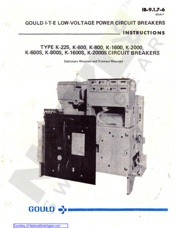
18-9.1.7-6GOULD I-T-E LOW-VOLTAGE POWER CIRCUIT BREAKERSPAGE 4. ':-252621828161519142113121711 432452710986231. Arc Chute2. Auxi I iary Switch3. Secondary Sepa rable Contacts4. Racking CamAssembly5. Overcurrent Trip Device6. Posit ioni ng Pins7. Closing Sp ring Charg ing Moto r8. Escutcheon Assembl y9. Automa ti c Tr ip Ind ica tor10. Moto r Disconnect Swi tchFig. 1 -11.12.13.14.15.16.17.18.19.20.Locking HaspElectr ical Close Push ButtonManual Trip Button"OPEN" or "CLOSED" Ind icatorRacking Shut terClosi ng Spring Charge Indica torManual Close LeverSe lf Align ing Dust PlateNamep IateLi fling Yoke21.22.23.24.25.26.27.28.Rack ing CrankRemovab Ie Mai ntenance HandIeTrackLatchRe taining SerewRetainerPositi on IndicatorCradleTypical Electrically Operated, Drawout TypeK-1600 Circuit Breaker)Courtesy of NationalSwitchgear.com
GOULD I-T-E LOW-VOLTAGE POWER CIRCUIT BREAK ERSIB-9.1.7-6PAGE 5CLOSING SPRING OPERATION (Manually Operated)In one continuous downward pull of the handle thetwo closing springs are charged, and near the end ofthe stroke are discharged to fast close the circuit breaker.During closing, the two opening springs are charged.ESCUTCHEON OPERA TING FEATURESManually and electrically operated circuit brea ke rsore provide d with an extend ib le escutcheon face plate.This escutcheon provides a central area for the controlswhich are mounted directly on the circuit breaker.The controls for the electrically operated circuitbreaker (Figure 1 ) included in the escutcheon faceplate are: ( 19) nameplate giving the various ratingsassigned to the particular type of circuit breaker, ( 13)manual trip button, ( 17) manual close lever, ( 12) electrical close push button switch, ( 10) motor disconnectswitch, ( 14) "OPEN" and "CLOSED " position indicator,( 9) automatic trip indicator with optional facilities foralarm indication and for lockout, ( 11) means for padlocking the circuit breaker in the "CONN ECTED ", " TEST"or "DISCONNECTED" position and ( 16) closing springcharge indicator. Handle ( 22) is normally removed andis used for emergency closing spring charging or maintenance work.The manually operated circuit breaker includes amanual closing handle but does not include the electrical close push button switch, motor disconnect switch,manual close lever, spring charge indicator or maintenance handle.All d rawout circuit breakers have the racking shutter( 15) that must be raised to allow inserting of the racking crank ( 2 1).A self-aligning dust plate ( 18) immediately behindthe escutcheon face plate is used to exclude dust fromthe circuit breaker comportment. On drowout type circuit breakers, the escutcheon face will protrude throughthe front door of the compartment when the circuitbreaker is in the " TEST" and "DISCONNECTED" positions. In these positions, the dust plate still functions toexclude dus t.Circuit Breaker Nameplate ( Figure 1, Ite m t 9)The circuit breaker nameplate contains informationregarding ( l ) the manufacturer's name and address,( 2) type of circuit breaker design, ( 3) serial numberof circuit breaker, ( 4) continuous curre nt ra ting offrame size, ( 5) short circuit current roting at rated voltages, (6) frequency, (7) short time current.Manual Charging Handle (Manually Operated)The manual charging handle is a T-shaped lever usedon manua lly operated circuit breakers to charge theclosing springs and close the circuit breaker in one continuous downward stroke.Manual Trip Button ( Figure 1, Item 13)The manual trip button, when pushed, trips the circuit breaker to " OPEN."Courtesy of NationalSwitchgear.comCircuit Breaker " OPEN" or "CLOSED" Indicator(Figure 1, Item 14)This indicator shows the physical position of the circuit breaker contacts.Automatic Trip Indicator (Figure 1, Item 91(Not including undervoltage, alarm switch or lockout)The automatic trip indicator is provided as standardequipment on the K-line circuit breakers and is usedto indicate the operation of the overcurrent trip device.This device is an indicator only and does not preventthe circuit breaker reclosing.Upon an overcurrent trip operation, the indicatorprotrudes from the front plate approximately 1h inch.The automatic trip indicator should be reset aftereach trip indication by pushing back into its normal latchposition . The operator should investigate the cause oftripping before resetting the automatic trip indicatorand subsequent reclosing the circuit breaker afte r a noutage which results in an operation of the indicator.Automatic Trip Alarm Contacts (Hand Reset)( Figure 1, Item 9 )An alarm switch for remote electrical indication, whichis optional, shows when automatic tripping has occurred.This is accomplished by adding a. precision snap switchto the automatic trip indicator assembly. The automatictrip indicator actuates the roller on the alarm switchwhich in turn causes a normally open contact to closeand a normally closed contact to open an overcurrenttrip. The alarm contact is manually reset by pushing thetrip indicator ( 9) bock into its norma l position.Automatic Trip Lockout ( Hand Reset) ( Figure 1, Item 9)An additional device {which is also optional ) ma y beadded to the automatic trip indicator assembly devicewhich serves to mechanically prevent reclosing the circuit breaker after an automatic trip operation. Whenthe trip indicator is pushed in, the circuit breaker mechanism can then be operated to close the circuit breakercontacts.Padlocking Device (Figure 1, Item 11 )All K-line circuit breakers ore equipped with meansof padlocking the circuit breaker mechanism in a tripfree position . This is a ccomplished by the use of a locking plate to maintain the manual trip button in a tripping direction when the locking plate is held forward byo ne o r more padlocks. To obtain the condition for padlocking the circuit breaker in the open position, the manual trip button is pushed inward. Then the padlock plateis pulled out and the padlock inserted into the verticalslot. In this position, the mechanism is maintained tripfree and the contact arm cannot be moved to the closedposition.O n circuit breakers equipped with drawout mechanism,the padlocking device is associated with the drawoutinterlocking mechanism so that the circuit breaker cannot be moved from any of its three basic drawout p ositions of " CONNECTED ", " TEST" or " DISCONNECTED"with the padlocking in effect.
18-9.1.7-6GOULD 1-T-E LOW-VOLTAGE POWER CIRCUIT BREAK ERSPAGE 6Closing Spring Charge Indicator (Electrically Operated l(Figure 1, Item 16)Under normal operating conditions, the closing springsare au tomatically charged after each tripping operation.However, there are occasions when the springs will bein a discharged state. Therefore, it is desirable thatmeans be available to indicate the charged or unchargedcondition of the closing springs. This is accomplishedby a visual indicator seen through an aperture in theescutch4!on plate. The indicator is marked " SPRINGSCHARGED" and " SPRINGS UNCHARGED."Motor Disconnect Switch (Electrically Operated I(Figure l, Item l 0)The motor disconnect switch is a double pole, singlethrow toggle type switch connected in series with thecharginp motor circuit and is used to disconnect themotor from the voltage source. This cut-off switch isused ( l ) , when it is desirable to prevent automaticrecharging of the closing springs just prior to taking thecircuit breaker out of service for maintenance and ( 2 I,for control wiring dielectric test. The motor must be disconnected for the control wiring dielectric lest and subsequently tested at 540 V ac or 760 V de.Electrical Close Push Button (Electrically Operated I(Figure l, Item l 2 IThe electrical close push button is used to electricallyclose the circuit from the escutcheon. This contact isconnected in series with the latch release coil ( 52X I .Energizing the latch release coil allows the chargedsprings to close the circuit breaker.Manual Close Lever (Electrically Operated )(Figure 1, Item 17)The manual close lever is provided on electricallyoperated circuit breakers to provide a means of closingthe breaker without control power.Racking Mechanism (Drawout Breaker)The racking mechanism may be used to move thecircuit breaker to any one of its three positions ("CONNECTED", " TEST" or " DISCONNECTED" I. All of thesepositions are attainable with the cubicle door closed.The racking shutter ( 15, Fig. 1 I, w[liefl must be lifted togain access to the racking mechanism, is interlocked withthe circuit breaker so that the circuit breaker contactsmust be open before the shutter may be lifted to rackthe circuit breaker to another position. The circuitbreaker can not be closed when the shutter is open.The circuit breaker may be padlocked open by meansof the locking hasp. This automatically locks the rackingmechanism . .With the "TRIP" button ( l 3, Fig. l I depressed, the locking hasp ( 11, Pig. l ) may, be pulledoutward, accommodating from one to three padlocks,when the shutter is closed and the circuit breaker istripped. The shutter can not be lifted and the breakercontacts can not be closed when the locking hasp isrestrained by one or more padlocks.There are two sets of arrows and indicating linesto show the circuit breaker position. One set is utilizedwith the compartment door closed and one set withthe door open.Courtesy of NationalSwitchgear.comOPERATION OF DEVICESElectro-Mechanical Overcurrent Trip DevicesType K-225 thru K-2000 Circuit Breakers(Figures 14 thru l 8 IIAJ Type OD-3 General Purpose Overcurrent TripDevice. The type OD-3 overcurre nt trip device, for general purpose applications, provides long-time delay tripping on modera te overcurrents which are above thelong-ti me pickup setting; and instantaneous tripping onfault currents above the instantaneous trip setting. Thisdevice must be properly set to provide adequate protection for an electrical system. Three adjustment screwson the bottom of the device provide independent controlof the long-time pickup, instantaneous pickup andamount of time delay. The nameplate of this deviceshows th e setting of these adjustments and the range ofsettings which are available. For information on thetime-current characteristics of this device, request a copyof TD-6693 .CBI Type OD-4 Selective Overcurrenl Trip Device.The type OD-4 overcurrent trip device, for selectivetripping applications, provides long -time delay andshort-time delay tripping. Independent adjustment ofboth pickup and time delay is provided for both typesof tripping. The namelate of this device shows thesettings whlch are available. For information on thetime-current characteristics of this device, request a copyof TD-6694.(CJ Type OD-5 Triple-Selective Overcurrent Trip Device. This overcurrent trip device is similar to the OD-4except that an instantaneous trip characteristic is addedto the long-time delay and the short-time delay functions provided on the OD-4. For information on thetime-current characteristics of this device, request a copyof TD-6695.IO I See Table l on facing page for complete list ofElectro-Mechanica l standard overcurrent trip devicesavailable. See Maintenance Section for adjustments.Power Shield Solid State Overcurrent Trip DevicesType K-600S thru K-20005 Circuit Breakers(See Figure 19 IThis device includes the power supply sensors, overcurrent sensors, Power Shield solid state logic assembly,magnetic latch and the interconnecti ng wiring. Eachphase of the circuit breaker has a power supply sensorand overcurrent sensor. The trip elements that are available are: long-time delay, instantaneous, short-timedelay and ground fault. On a 3-phase 4-wire system,an add itional remote sensor, mounted in the neutralbus, is required for complete ground fault protection.The logic assembly is mounted near the front of thecircuit breaker and with the cubicle door open theovercurrent control panel is readily accessible. Thisdevice must be properly set, as required by individualcircuit conditions, to provide adequate protection for anelectrical system. The movable plugs on the controlpanel provide independent control of the long-time,short-time, instantaneous and ground fault pickup andamount of time delay. The overcurrent device, with theexception of ground fault, will trip at the value of theAMPERE TAP setting times the plug setting of the various
GOULD I-T-E LOW-VOLTAGE POWER CIRCUIT BREAKERS18-9.1.7-6PAGE 7pickup e lements. The ground fault trip value will bethe plug setting value times 100, as indicated on thenameplate.IA! Type SS-3. This trip device is for general purpose applica tion. It provides long-time delay trippingon mode rate overcurrents, which are above the longtime pickup settings, and instantaneous tripping on fau ltcurrents above the instantaneous trip setting. For information on the time-current characteristics of this device,request o copy of TD-6966 ( TD-9001 *).18 1 Type SS-4 Selective Overcurrent Trip Device.This trip device, for selective tripping application, provides long-time delay and short-time delay tripping.For information on the time-curre nt characteristics ofthis device, request a copy of TD-6967 (TD-9002 ).(Cl Type SS-5 Triple-Selective Overcurrent Trip Device. This device includes the trip elements found in boththe SS-3 and SS-4; i.e., long-time delay, short-timedela y, and instantaneous tripping. For information onth e time-current characteristics of this device, requesta copy of TD-6967 (TD-9002*).( D l The above three solid state overcurrent tripdevices are available with ground fault protection andore designated by the types SS-3G, SS-4G and SS-5G.For information on the time current characteristics of thisfeature, request a copy of TD -6968 ITD-9005 ).IEl See Table lA for a complete list of standardSolid State overcurrent trip devices.TABLE 1STANDARD ELECTRO-MECHANICAL OVERCURRENT TRIP DEVICESTrip ElementOvercur rentTime -C urrentDeviceLttRg- Short- Inst an- Cha r acterist icTypeCurveTimeTi me 6xxTD-6695None00 - 7xxOD-8NoneOD-9xxTD-669900- 10TD -6699xNOTE : DD-3 long-ti me delay e l ement has one timedel ay band only. All other long- time & short-timedelay elements have th ree time delay bands.TABLE 1ASTANDARD SOLID STATE OVERCURRENT TRIP DEVICESOvercurrentDeviceTypeLongTi meTr ip EI em en tSho rt- In st an Ti me tan eo us Time-Cur rent Charact eris tic .Cu rveDevice inDe vi ce inRED CASEGRAY CASE*T0- 6966TD-9001TD-6966TD -6968TD-9001T0 -9005TD 9002TD -6967TD -6968TD-9002TD-9005NOTE: Time- current characteristic curves are not included in thisbook because separate coordination curves are normally providedwith each order. When field ca li bra tion i s pe r formed, necessaryin struct ion books (ref er to paae 18) wi 11 be prov id ed and wi 11include all pert inen t timina informat ion . Device in GRAY CASE (Current Manufacture)TD- 6966, TD- 6967 & T0-6968 apply to Device in RED CASECourtesy of NationalSwitchgear.com
18-9.1.7-6GOULD 1-T-E LOW-VOLTAGE POWER CIRCUIT BREAKERSPAGE 8rangements. They are mechanically interconnected withthe main circuit breaker contacts such that, with the circuit breaker closed, the "a" contacts are closed. Withthe circuit b reaker open, the "b" contacts are closed .Control Device (Electrically Operated)The control device (Fig . 12) is furnished on electrically operated circuit breakers. The device is mountedbelow and to the left of the mechanism. The controldevice contains three electrical components, the limitswitch (LS), the lockout relay ( 52Y), and the latchrelease relay ( 52X). The schematic diagram of thecontrol circuit (Fig. 2) illustrates the function of thisdevice. In addi tion to its electrical functions, the baseof the device provides a terminal block for the circuitbreaker wiring.The purpose of the lockout relay ( 52Y) is to requirethat, if the remote or local close contacts are closed,resulting in the charging springs discharging, the closecontacts must first be released (opened) before thebreaker can be reclosed. This prevents closing the circuit breaker more than one time unless the close contacts are first released.Undervoltage Trip DeviceThe electrically reset undervoltage trip device is asingle-phase device which automatically tri ps the circuitbreaker when the I ine voltage decreases to 30 to 60 percentof the rated voltage. This device may be furnished either forinstantaneous trip operation or with adjustable time delaytripping of 1.5 to 15 seconds. The undervoltage trip deviceis an integral unit which may be added to the circuitbreaker either at the factory or in the field.The undervoltage device may be connected so thatthe automatic trip indicator (Figure 1, Item 9) will protrude from the front plate when the breaker is tri ppedby the undervoltage device.See Table 4, page 20, for electrical characteristics.Auxiliary Switches (Figure 1, Item 2)The auxil iary switches contain the "a" and "b" contacts (Fig. 2) and are furn ished in 4 or 8 contact or-II:- :CLOSE\!/I :TR IPI: ::. CLOSEqt,5f 56lC3CLOSE 11Cl9i:IsIII ·asTlSr--1BI286T43 .l131652LEGEND14 2Y.--- .,3"81TC Trip Coi I51C3124352Cl!d.!::.bM Cha1gang Motor133C2,.tr6.5ZYI1563652YT17MOS - Charging Mo t or Disconnec t S i tchCE5LS/I. LS/3 - Limi t Switch ContactsClosed When Sp11ngs a1e Discharged .Open When Sp11ngs are Charged17CEILS/2 - Limit Swit ch ContactsOpen When Springs are Oi scha 1ged.CI osed When Springs are Cha 1gedC!5Ml 2.I1---1l83B21116 7lSTCLOSEI52Y 42L:·TSL/a - Contac t Cl osed When Breaker i s Cl osedL/b - Contac t Open When Br eake 1 i s CI osed52X - Latch Re I ease Coi I52Y - Con trol Coal52Y/1 - Lockout Re lay Con t ac t. Normal l y Open52Y/2 - Lockout Relay Contact. No1mal l y ClosedORAWOUTSTAT ION ARYFig. 2 -Typical Schematic Diagram of Control Circuit)/Courtesy of NationalSwitchgear.com
GOULD 1-T-E LOW-VOLTAGE PQ.WER CIRCUIT BREAKERS18-9.1.7-6PAGE 9INSTALLATION, INITIAL TESTING AND REMOVAL( Drawout & Stationary lFOR SAFETY: When installing or removing stationarybreakers, the supply for primary and control circuits mustbe de-energized at all times. Testing of stationarycircuit breakers to be done with the primary supplycircuit de-energized.For initial installation of drawout breakers in the"CONNECTED" position, the supply for the primarycircuit shou ld be de-energized. Testing of the drawoutbreaker to be done in the test position.NOTE: (K-225 thru K-2000 Circuit Breakers) Prior toinserting the cjrcuit . breaker into the switchboard andwith the breaker in the upright position, exercise thethree long time armatures ( % " wide armatures) severaltimes until resistance to motion has increased, indicatingthat the oil dashpot is functioning properly. Impropero peration can resu lt because the circuit breaker is shipped or stored on its back. This causes the oil in thedashpot to be displaced and an air bubble can be trapped under the piston. The exercise removes the air topermit proper operation.INSTALLATION (Stationary Type!Lifting yoke ( 20, Fig. 1 ) should be used to move thebreaker to the switchboard; however, other handlingmeans wil l be required to move the breaker into position inside the switchboard.INSTALLATION Drawout Type!'To insert the circuit breaker into its compartment,proceed as described below:(Refer to Fig . 1)1. The circuit breaker must be in the "OPEN" position, the racking crank turned in the counterclockwisedirection fully against its stop, and the motor disconnectswitch ( 10) (electrically operated circuit breakers only)in the "OFF' position.2. Open the compartment door and pull out theright-hand and left-hand tracks ( 23) to the fully extended and latched position.3. Using a lifting yoke, lower the circuit breaker sothat the positioning pins ( 6) (two each side of circuitbreaker) rest in the cut-out sections of each track ( 23 ) .4. Remove the lifting yoke and push the circuitbreaker toward the comportment. The circuit breakerwill slide in the cut-out sections of the tracks until thepositioning pins reach the end of the cutouts. An additional positive push will automatically release the twolatches ( 24). This a llows the circuit breaker to movetoward the compartment until the rocking ca ms ( 4) stopagainst their guides on the cradle ( 28).5. Lift shutter ( 15) covering the rocking opening,insert racki ng cra nk, and turn crank clockwis. , passthroug h the " DISCONNECTED" position, until the position indicator on the cradle (left side)
which are mounted directly on the circuit breaker. The controls for the electrically operated circuit breaker (Figure 1 ) included in the escutcheon face plate are: ( 19) nameplate giving the various ratings assigned to the particular type of circuit breaker, ( 13) manual trip button, ( 17) manual close lever, ( 12) elec