Transcription
LC Tank Voltage Controlled OscillatorTutorialbyProfessor John Starr HamelIntroduction byRyan Norris,Presented to the UW ASIC Analog Group and edited byRyan Norris,Waterloo, Ontario, Canada, 2005c 2005
This tutorial was created from a set of hand written notes that were preparedby Professor John Starr Hamel at the University of Waterloo, Ontario, Canada foruse in E&CE 439, an undergraduate course in Analog Integrated Circuits.ii
AbstractThis tutorial provides an introduction to the fundamentals of LC tank voltagecontrolled oscillator analysis and design.iii
AcknowledgmentsI would like to thank Professor John Starr Jamel for allowing the UW ASICAnalog Group to utilize his tutorial within the UW ASIC Analog Group.iv
DedicationThis tutorial is dedicated to the students of the UW ASIC Analog Group.v
Contents1 Introduction12 LC Tank Voltage Controlled Oscillator Tutorial42.1Voltage Controlled Oscillator Analysis and Design . . . . . . . . . .42.1.1Small Signal (a.c.) Analysis . . . . . . . . . . . . . . . . . .62.1.2Design Constraints . . . . . . . . . . . . . . . . . . . . . . .122.1.3Transistor Non-Idealities . . . . . . . . . . . . . . . . . . . .132.1.4Determining Transistor Width ’W’ . . . . . . . . . . . . . .162.1.5VCO Design Procedure . . . . . . . . . . . . . . . . . . . . .19Oscillator Phase Noise . . . . . . . . . . . . . . . . . . . . . . . . .202.2.1Quality Factor ’Q’ of an Oscillator . . . . . . . . . . . . . .232.2.2Dependence of Phase Noise on Q and Offset Frequency . . .252.3MOS Varactors . . . . . . . . . . . . . . . . . . . . . . . . . . . . .292.4MOSFET Models . . . . . . . . . . . . . . . . . . . . . . . . . . . .332.2Bibliography42vi
List of Figures2.1LC Tank. . . . . . . . . . . . . . . . . . . . . . . . . . . . . . . . .42.2Balanced NMOS VCO. . . . . . . . . . . . . . . . . . . . . . . . . .52.3Balanced NMOS VCO with each tank represented by a series impedance. . . . . . . . . . . . . . . . . . . . . . . . . . . . . . . . . .72.4VCO of Figure 2.3. . . . . . . . . . . . . . . . . . . . . . . . . . . .82.5Bandwidth of an LC tank oscillator. . . . . . . . . . . . . . . . . . .92.6MOSFET parasitic elements. . . . . . . . . . . . . . . . . . . . . . .142.7LC tank parasitic elements. . . . . . . . . . . . . . . . . . . . . . .152.8MOSFET I-V characteristics. . . . . . . . . . . . . . . . . . . . . .182.9Illustration of phase noise in the time domain. . . . . . . . . . . . .212.10 Illustration of phase noise in the frequency domain. . . . . . . . . .222.11 Calculation of Q from the frequency response. . . . . . . . . . . . .232.12 LC tank VCO open-loop transfer function. . . . . . . . . . . . . . .242.13 LC tank and phase function. . . . . . . . . . . . . . . . . . . . . . .252.14 Phase noise in the signal path. . . . . . . . . . . . . . . . . . . . . .252.15 Noise shaping in an oscillator. . . . . . . . . . . . . . . . . . . . . .272.16 Nonlinear mixing. . . . . . . . . . . . . . . . . . . . . . . . . . . . .282.17 Tuning characteristic for PMOS capacitor where Body, Drain andSource are connected together. . . . . . . . . . . . . . . . . . . . . .302.18 MOS internal capacitors. . . . . . . . . . . . . . . . . . . . . . . . .302.19 Fingered MOSFET gate. . . . . . . . . . . . . . . . . . . . . . . . .312.20 IMOS C-V characteristic. . . . . . . . . . . . . . . . . . . . . . . . .32vii
2.21 MOSFET transistor cross section and symbols. . . . . . . . . . .332.22 MOSFET energy band diagram. . . . . . . . . . . . . . . . . . . . .342.23 3D MOSFET. . . . . . . . . . . . . . . . . . . . . . . . . . . . . . .352.24 Detailed 3D MOSFET, and MOSFET output Drain characteristics.352.25 MOSFET small signal equivalent circuit. . . . . . . . . . . . . . . .372.26 NMOS depletion capacitance. . . . . . . . . . . . . . . . . . . . . .382.27 NMOS capacitances. . . . . . . . . . . . . . . . . . . . . . . . . . .392.28 Gate-Drain overlap region. . . . . . . . . . . . . . . . . . . . . . . .40viii
List of Tables1.1List of ideal VCO specifications. . . . . . . . . . . . . . . . . . . . .ix2
Chapter 1IntroductionThe Analog Group, of the UW ASIC Group, has decided to concurrently designtwo different VCO (Voltage Controlled Oscillator) topologies. This introductionprovides some of the reasoning for why the Analog Group has chosen to designVCOs that have the ring oscillator and the LC tank topology.There are two types of VCOs that one may choose to design:1) waveform oscillators2) resonant oscillators.Waveform oscillators:1) ring oscillator topology2) relaxation oscillator (which has poor phase noise performance).Resonant oscillators:1) LC tank oscillator topology2) crystal oscillator (which is neither integrated nor tunable).Ideally a given VCO topology would be able to meet all of the specifications listedin Table 1.1.1
Chapter 1: Introduction2Table 1.1: List of ideal VCO specifications.1)2)3)4)5)6)low noiselow powerintegratedwide tuning rangesmall die area occupancyhigh frequency (GHz)As discussed below, it is unlikely that either the ringVCO (ring oscillator VCO) orLCVCO (LC tank VCO) topologies can meet all of these specifications.Through a comparison of ringVCOs and LCVCOs, the following advantages anddisadvantages may be formulated.RingVCO advantages:1) highly integrated in VLSI2) low power3) small die area occupancy4) wide tuning range.RingVCO disadvantages:1) As frequency increases phase noise and jitter performance degrades.LCVCO advantages:1) outstanding phase noise and jitter performance at high frequency.LCVCO disadvantages:1) contains an inductor and a varactor (variable capacitor) which are large areacomponents, and thus is not as suitable for VLSI
Chapter 1: Introduction32) high power consumption3) occupies a large die area4) small tuning range.Clearly, the ringVCO is most suitable for low power, highly integrated applicationsthat require a large tuning range and a low die space area. In contrast, the LCVCOout performs the ringVCO in low noise applications.For mobile wireless applications one desires low power, hence the ringVCO maybe of choice. However, wireless applications require outstanding noise (phase noiseand jitter) performance at high frequency, hence the LCVCO may be of choice.Having said that, there may be specific applications where either the ringVCO orthe LCVCO topology may be optimized to perform sufficiently well.The aforementioned advantages and disadvantages should hold true for the fabrication technologies (0.13µm CMOS, etc) that are predicted, by IRTS road map,to be in use in the future. Hence, a design decision - to utilize either a ringVCOor a LCVCO - that is based on the above advantages and disadvantages shouldbe a valid decision in the future when silicon CMOS fabrication technologies scalefurther into the deep deep sub-micron regime.This analysis illustrates that to be able to target the most diverse range of applications, one should be knowledgeable in the design and optimization of both theringVCO and LCVCO topologies.The forthcoming tutorial provides fundamental information on the analysis anddesign of a LCVCO.Ryan Norris,2005 UW ASIC Analog Group leader
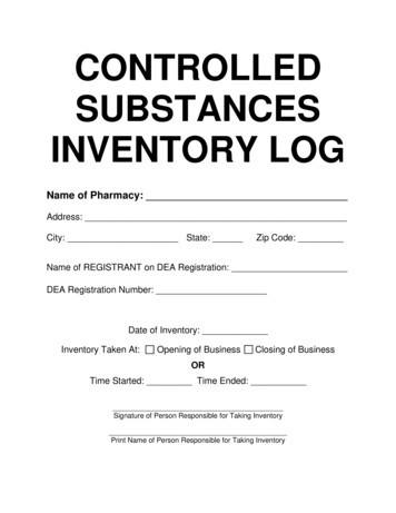
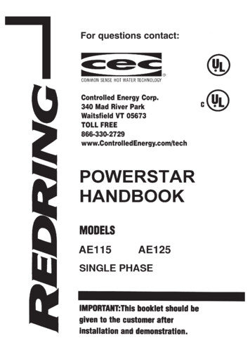
Chapter 2LC Tank Voltage ControlledOscillator TutorialPlease see the Section entitled Bibliography at the end of this document for a listof useful references [1] [2] [3] [4].2.1Voltage Controlled Oscillator Analysis andDesignAn LC tank VCO can be thought of as two 1-port networks connected together.Figure 2.1: LC Tank.One 1-port represents the frequency selective ”tank” where the oscillations occurand the other 1-port represents the active circuit that cancels the losses in the tank.Oscillations can occur when:4
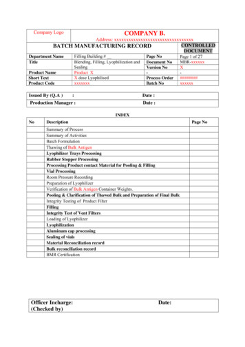
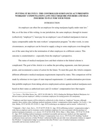
Chapter 2: LC Tank Voltage Controlled Oscillator Tutorial5i) the negative conductance of the active network cancels out the positive conductance (loss) of the tankii) the closed loop gain has zero phase shift.Conditions i) & ii) above amount to a closed loop gain greater than or equal tounity magnitude with no imaginary component.The first step in designing an oscillator is to choose a circuit topology or type.For this example a balanced NMOS VCO will be chosen.Figure 2.2: Balanced NMOS VCO.The only losses being assumed in Figure 2.2 are those associated with the inductor. In reality there would also be losses associated with the variable capacitors(varactors) and the MOSFETs (the active devices).In practical integrated VCOs the inductors are on-chip spiral inductors with lowquality factor that dominates the losses of the VCO tank.The quality factor QL of the inductor is given by
Chapter 2: LC Tank Voltage Controlled Oscillator TutorialQL ωo LR6(2.1)whereωo is the oscillation frequency [rad/s]L is the value of the inductance [H]R is inductor’s equivalent series resistance [Ω].QL in practical silicon RF IC processes ranges from 5 to 10.Values of on-chip inductances range from 0.1 nH to 10 mH in practical RF ICprocesses.It can be shown that the oscillation frequency of the circuit shown in Figure 2.1,assuming ideal varactors and MOSFETs is given by1ωo 2LCr21 R2 CL(2.2)It can also be shown, under the same set of assumptions that the gm of eachMOSFET must begm RCL(2.3)for oscillation to occur.2.1.1Small Signal (a.c.) AnalysisThe oscillator is essentially a differential pair that have been cross-coupled in apositive feed back configuration.
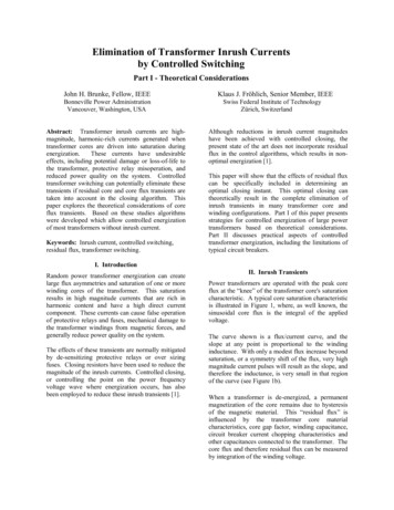
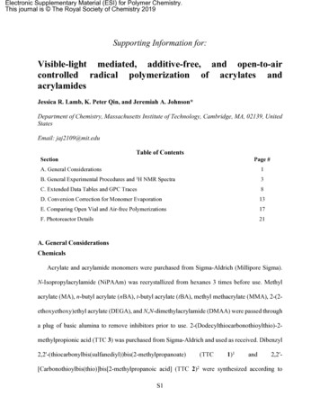
Chapter 2: LC Tank Voltage Controlled Oscillator Tutorial7Figure 2.3: Balanced NMOS VCO with each tank represented by a series impedance.The input of each transistor in the differential pair has been connected to the outputof the opposite transistor.The output voltage vo v1 v2 is a differential output signal.v1 which is the input signal to M1 is also the single ended output of M2 .Each individual transistor in the pair is essentially a common-source amplifier witha complex, tuned load comprised of a lossy inductor in parallel with a capacitor.The Zs load is called a ”tank” circuit since it holds the oscillating energy like atank at the oscillation frequency.The two separate tanks form a differential load to the differential pair where node’A’ remains, to first order, at the same potential during oscillations.Node ’A’ is a ”virtual” a.c. ground point in the same manner as the virtual groundthat exists in a normal differential amplifier.
Chapter 2: LC Tank Voltage Controlled Oscillator Tutorial8Node ’A’ is not a complete a.c. short, however, since, ideally, there should be aninfinite a.c. impedance between this node and the power supply rail VDD .A proper active current source must be designed to provide the d.c. biasing to node’A’ and hence M1 and M2 as well as maintaining a high a.c. impedance betweennode ’A’ and the supply rail.If the a.c. impedance between node ’A’ and VDD is not high, then RF energy will”leak” out of the tanks into the supply rail destroying the oscillations.Figure 2.4: VCO of Figure 2.3.For small signal (a.c.) analysis the current source of Figure 2.3 behaves as an opencircuit. The VCO of Figure 2.3 can then be represented by Figure 2.4 as two 1-portnetworks. Assuming ideal MOSFETs (i.e. no parasitic resistances or capacitances),the entire differential amplifier can be modeled as a negative resistance R (ornegative conductance Gm g2m ).The two tank circuits appear in series whereZT 2Zs RT jXT 2(Rs jXs )(2.4)The oscillation condition requires that the closed loop gain (around the two 1-ports)be of at least unity magnitude and zero phase angle. The zero closed loop phasecondition implies that at the frequency of oscillation, ωo , XT (ωo ) 0.
Chapter 2: LC Tank Voltage Controlled Oscillator Tutorial9The magnitude of the amplifier negative resistance must be at least as large asRT (ωo ), the total resistive or real loss of the two tanks. setting XT (ωo ) 0 determines ωo and setting R1 g2m the minimum gm of each MOSFET for oscillation to occur.1RT (ωo )determinesIn general, the negative resistance of the differential pair must overcome all realresistive losses in the oscillator circuit. An ideal oscillator has no losses with infinitevoltage swing at precisely one frequency.The presence of losses results in a finite voltage swing over a narrow spread offrequencies.How ideal an oscillator is can be directly related to the ”quality factor” of the tank.Figure 2.5: Bandwidth of an LC tank oscillator.At resonance, a pure LC tank with no losses presents infinite impedance to anapplied signal across the tank. This implies that the output voltage across the tankwill be infinite if the tank is driven by a source with infinite impedance.If the tank has real losses, however, even if it is driven by an infinite impedancesource (i.e. Rin 0), the losses can be modeled as if the lossless tank had a finiteimpedance load, Rp 6 .
Chapter 2: LC Tank Voltage Controlled Oscillator Tutorial10The finite impedance load Rp will ”de-Q” the tank resulting in a finite outputvoltage.One definition of quality factor or ”Q” isQ ωoω1 ω2(2.5)as per Figure 2.5.It can be shown that Equation 2.5 is also equal toQloaded Rpωo L(2.6)where ωo is the resonant frequency of the lossless tankwo 21LC(2.7)Equation 2.6 is known as a ”loaded Q”.The ”loaded Q” can be related to something called a ”component Q” where theparallel resistance, Rp , modeling the total losses of the tank can be related to theindividual losses of the inductor and capacitor components themselves.The component Q of the inductor is given byQL ωo LRwhere R is the series resistance of the inductor.(2.8)
Chapter 2: LC Tank Voltage Controlled Oscillator Tutorial11The component Q of the capacitor is given byQC 1Rωo C(2.9)where R is the series resistance of the capacitor.The total loaded Q can then be estimated as1Qloaded 11 .QL QC(2.10)Often capacitors have much higher component Q’s than inductors in silicon integrated processes (though this may not be the case if varactors are used as thecapacitor) such thatQL QC(2.11)Then QL Q
The input of each transistor in the differential pair has been connected to the output of the opposite transistor. The output voltage v o v 1 v 2 is a differential output signal. v 1 which is the input signal to M 1 is also the single ended output of M 2. Each individual transistor in the pair is essentially a common-source amplifier with